田宫MAN遥控拖头模型装配说明书
COMPANION OEM 拖车连接器安装手册说明书

COMPANION OEM YOUR TOWING ADVENTURE BEGINSDON'T WORRYYOUR HITCH WAS MADE RIGHT HERE.The only thing keeping your truck and your trailer connected are those relatively small pieces of engineered steel. The hitch you choose matters not only to your safety, but to the safety of our roads.That’s why we treat the manufacture of your trailer hitch with the respect it deserves. We insist on American-made steel, like the sheet steel made in Burns Harbor, Indiana or the round bar made at a mill in Norfolk, Nebraska thatbecomes the gooseneck ball. When the strength and flexibility of the steel can mean life or death, we trust the U.S. steel mills with their finely controlled processes and specifications we can trust.Only in America could a small-town farmer start a business in a garage and watch it grow the way B&W has over the last 35 years. The 600 employees in Humboldt, Kansas are proof that American Manufacturing can compete in a global economy. We are grateful that you have put your trust in us.- Joe Works, Owner1" thick, wrap-around jaws fityour kingpin perfectly, eliminatingsloppy starts and stopsVarious front-to-back andheight adjustments areavailable with each model WELCOME TO THE FAMILY.YOU MADE A GREAT CHOICE.We designed our jaws and handle to work with a cam mechanism. When the handle is pinned closed, the cam keeps the jaws from opening.When the handle is open the cam allows the jaws to open, even if you are in a bind because of unlevel ground. If the handle is open, you may go ahead and drive out of the jaws. They will open as you pull away.Our jaws are a full inch thick cast material and the left and right jaw are machined together to create a precise connec-tion to your kingpin. Then the jaws are wired together, plated, and assembled as a pair. Learn more about this process on the B&W Trailer Hitches' YouTube channel.The Companion allows side-to-side movement and articulationwhen you are maneuvering or on uneven ground.The shock absorber, located on one side of thecoupler, cushions that movement and allowsgentle side-to-side movement without theslamming. Sit back, and enjoy the ride.Machining on the jaws must be+/- .002 of an inch. (A piece ofpaper is about twice that thick.)OUR PROCESSES?THE B&W DIFFERENCECam withHandle Open Cam With Handle ClosedMount the pivot arms using one of the locations illustrated. These locations allow flexibility in coupler height (vertical adjustment) and distance from the cab (horizontal adjustment). Choose a location so that your trailer will be as level as possible and have adequate turning clearance while towing.Check for clearance between your fifth wheel and the sides of your truck bed. Allow several inches so that uneven ground doesn't cause contact. Adjust the Companion to a higher position or your kingpin (if it is adjustable) to a lower position to affect this distance.(19")(18")(17")4" Behind AxleHorizontal Adjustment2" Behind AxleOver AxleRAM2" in Front of AxleRAM COMPANION OPTIONSADJUST ARMS FOR PROPER CLEARANCERemove the latch pins from each handle and rotate the handles out. Place the Companion base over the attachment points and carefully lower it until the latch cams pass through the floor and the base rests flat against the top of the attachment points.Once the base is in place, turn each of the latch handles so the base is drawn firmly down onto the attachment points. You should feel some resistance with turning the handles as the base is drawn down. If any of the handles will not close or if they rotate freely with no resistance, the tension on the latch handles will need to beadjusted.If your handle needs tension adjustment. With a pair of needlenose pliers, un-bend and remove the cotter pin installed at thetop of the latch cam. Then adjust the height of the castle nut.To loosen the latch handle (handle is difficult to rotate orcannot be closed) rotate the castle nut counter-clockwise(loosen) with a 15/16" wrench or socket.To tighten the latch handle (handle rotates without anyresistance) rotate the castle nut clockwise (tighten) with a 15/16"wrench or socket.Use trial and error to find the correct latch tension for eachattachment point. After the tension is set, replace the cotter pinand re-bend the ends. You may have to rotate the castle nutslightly to allow the cotter pin to pass through.With the base firmly held down and each latchhandle closed, replace the latch pins removed instep one. Place the coupler on the pivot arms andpin in place.For more information refer to your instruction sheet.INSTALLING THE COMPANIONPlace Base in ReceiverPlace the Coupler on Pivot ArmsREMOVING THE COMPANIONUnpin and remove the coupler head.Remove the latch pins from each of the handles.Turn latch handles to the open position.Lift the base straight up and out of theattachment points.It is important to learn your manufacturer's weight limits (truck, fifth wheel, and hitch). Detailed instructions for comparing these weight limits to the actual weights of your set-up are found on the next few pages.Truck manufacturers give their trucks specific ratings after extensive testing. Tow ratings are based on the capacity of a truck’s engine, transmission andbrakes to safely handle the weight of a loaded trailer. For Gross Weight Ratings, the truck’s tires, frame, and suspension must be able to bear the load. Even if your Companion fifth wheel hitch is rated to tow your load, never exceed yourtruck's weight ratings.All of our hitches are tested for both strength and durability according to SAE J-2638, the latest standard for fifth wheel and gooseneck hitches.KNOW BEFORE TOWINGWithout proper knowledge, towing can be adangerous activity. If you are newto towing, we recommend"The Trailer Handbook: A Guide to Understanding Trailer and Towing Safety"from the National Association of Trailer Manufacturers. This booklet is available by going to .Locate your This is the maximum allowable weight of the fully loaded vehicle.You can find this, most likely, on the sticker inside your driver’s side door.You should also locate your from your truck manufacturer. This is the maximum allowable weight of the tow vehicle and the loaded trailer including all cargo and passengers. Find this in your owner’s manual or by calling your truck dealer.FINDING MANUFACTURER WEIGHT LIMITSInformation for 2010 and newer truck models can be found on B&W's website, .Once you have located your truck manufacturer’s weight ratings, transfer them into the corresponding boxes on the next two pages.your GVW*GVWRMUST BE MORE THANTake your loaded truck and loaded trailer to a scale at a truck stop, quarry or material supply center. For a small fee you can weigh your tow vehicle and trailer on their scale.Find your GCW (Gross Combined Weight)Weigh your fully loaded truck and trailer including all cargo, a full tank of gas and passengers.Find your GVW (Gross Vehicle Weight)Weigh just your truck with a full tank of gas, all your passengers and items in the cab and truck bed with your trailer loaded and attached, but not on the scale.Do Not Exceed Your Truck Manufacturer’s GVWR* Transfer Manufacturer’s Ratingsyour GCWGCWR=your Towing Weight–your Truck Weight =–your Truck Weightyour VTWFind your Towing Weight Weigh your loaded truck without the trailer attached. This is your truck weight.Subtract your Truck Weight from your GCW. This is your towing weight.your Towing WeightFind your VTW (Vertical Tow Weight) also known as Tongue Weight Subtract your Truck Weight from your GVW.MAX TOW RATINGyour VTWVTWR*Even though you may be under your vehicle’s Max Towing Rating, when yourGross Vehicle Weight (GVW) goes up, (more passengers, more cargo) your ability to tow the Max Towing Rating may not be possible, because:T H E G R O S S C O M B I N E D W E I G H T R AT I N G (G C W R ) M U S T N O T B E E X C E E D E D.IMPORTANT!MUST BE MORE THANyour GCWyour GVWMUST BE MORE THANRemove the coupler cam handle safetypin and use the cam handle to open the coupler jaws.Adjust the height of the fifth wheel trailer using the jack so that the kingpin plate is slightly lower than the top of the coupler.Back the truck towards the trailer, centering the trailer's kingpin in thecoupler, until the kingpin has engaged the jaws.Hook up brake and lighting connections before towing.ATTACHING YOUR TRAILERSafety PinPlace the truck in 'park', and put the emergency brake on.The trailer's landing gear should be firmly on the ground, supporting the weight of the trailer:The trailer should have wheels blocked:CONDUCT A SAFETY TESTBefore towing, you should conduct a safety test to make certain that you are properly hitched.Landing GearWheel BlocksUnpin the coupler handle and rotate to the open position to release the jaws.If the jaws do not open, that may be an indication that there is stillupward pressure on the jaws. Readjusting the landing gear mayrelieve that pressure. However, if the handle is open, the jaws willalways open as you pull away.Use the safety pin to lock the handle in the open position and when you are sure that the landing gear will support the trailer, move the truck forward to release the jaws from the kingpin.DISCONNECTING YOUR TRAILERSafety Pin Safety PinWheel Blocks Landing GearWHITE LITHIUM GREASEMULTI-PURPOSE• Lubricates and Protects • Water Resistant • Single UseLOVE YOUR HITCHLONGER!Grease the saddle through the grease zerk approximately every six months with multi-purpose grease. This allows the coupler topivot freely.As needed, grease the polyurethane bushings with high-grade lithium grease.Spread a thin layer of multi-purpose grease around the inside surface of the jaws where they grasp the kingpin. You may also want to apply some grease to the kingpin on your trailer.Lubricate the top surface of the coupler with automotive type chassis grease or use a nylon lube plate to provide a lubricated surface.There are four places on the Companion that you should lubricate regularly.HITCH MAINTENANCEHere is your first grease packet to get you started. If you need more, feel free to contact us at 800-248-6564.Lube plates come in all sizes. We recommend a 10" version, like this one infused with graphite, available at .LUBE PLATESAN ACCIDENT RARELY HAPPENS WHEN A HITCH IS BRAND NEW.I T HAPPENS AFTER YEARS OF WEAR FROMTHE ROAD.TAYLOR JONESDIRECTOR OF ENGINEERING,Watch howwe test.WHAT TESTING STANDARDS EXIST TODAY FOR GOOSENECK AND FIFTH WHEEL HITCHES?WHAT DOES SAE J2638 REQUIRE?SAE J2638 is the standard that establishes the minimum performance criteria for gooseneck and fifth-wheel hitches up to 30,000 lbs. Currently, the standard is a recommended practice and NOT a requirement to sell or use a trailer hitch.However, I strongly believe that anyone towing a gooseneck or fifth-wheel should be using equipment, whether it’s ours or another brand,that has been tested and passes the J2638 standards. I recommend customers ask before buying.The standard requires hitches to complete non-independent tests without loss of attachment. This means that if the damage occurred while driving, it would not allow the trailer to separate from the truck.The nine tests include static tests of force against the hitch in six directions and three dynamic tests of 300,000 cycles each. And while the standard allows you to use a different specimen for each test, my personal requirement for B&W is that a single specimen pass the dynamic tests and then also pass the static tests. I think this reflects what happens in the real world. An accident rarely happens when a hitch is brand-new.It happens after years of wear from the road.HOW DOES B&W USE THE TESTING STANDARD?Before we build a trailer hitch, we model it using CAD software. Then, in a digital environment, we subject it to the types of forces we know exist, using FEA (Finite Element Analysis). This modeling gives us a good idea of what we will see on the testing equipment and in real situations. From there, a prototype is built and we run it through the full gamut of J2638 tests at the max tow rating for the truck it is designed to fit.After the J2638 testing is complete, we also subject our designs to real world testing by using them to tow heavy trailers with different types ofWe are confident that our products are made without design or quality defects. However, if you believethat one of our products doesn't live up to our standards, we would make it right with you, our customer.If your product suffers damage because of an accident or misuse on your part, we will work to get you back on the road with as little cost and hassle to you as possible, because that is just being a good neighbor.We can’t keep your product in ‘new’ condition. Your product, and the finish will age through normal wear and tear. You should only use our products in the manner intended in their design. Most of our products require some maintenance to continue to work as they did when they were new.We appreciate it when our customers register their products with us.However, we offer our warranty even if you don’t.To register your product or download a copy of our limited lifetime warranty,visit /warranty.Like many, ours began in a garage in 1987, with two men and an idea. Roger Baker and Joe Works(the ‘B’ and the ‘W’) began building custom truck beds and quickly recognized away to improve the inconvenience of a gooseneck ball permanently welded in thebed. They designed a gooseneck hitch with the mounting hardware underneath thebed and a ball that turned over and stowed where it was used. The Turnoverball®Gooseneck Hitch was born.A few years later, they applied the same concepts to fifth-wheel hitches. Usingthe same under-bed mounting hardware and hole in the bed, they designed theCompanion™ with a single-point attachment that was removable when not towing.They also designed the Companion to be quiet and smooth when towing.While competitors take manufacturing to China and Mexico, Joe (Roger retired in1999) remains committed to using American-made raw materials and American Labor.“You don’t work for me, you work for the customer. We can compete in this global economy by designing better, using technology, and truly caring about our customers,” Joe affirmed.Our product line now includes all types of towing products manufactured under the 650,000 sqft. facility. In 2007, Joe began transferring ownership of the company to us, the now more than 600 employee-owners.OUR AMERICAN DREAM STORY。
P.T.O. instabus 技术手册:窗帘遥控器 N523C04 5WG1 523–1CB04
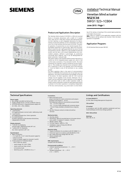
Product and Applications DescriptionThe Venetian blind actuator N 523/04 is a DIN rail mounteddevice in N-system dimensions with a width of 4 moduleunits. Only one AC 120V drive (motor) with electromechani-cal limit switches or with integrated electronics for discon-nection at the limit positions can be connected to one chan-nel of the 4-fold Venetian blind actuator N 523/04. The paral-lel operation of several drives on one channel requires the in-termediate switching of a special relay. Apart from the possi-bility to travel the sun-/ sight guard directly into one of its twofinal positions (via EIS 1 objects) it is also possible for both theshutter and the slats to be moved independently into inter-mediate positions, defined in percentages, by positioningcommands (EIS 6 objects). And it can be distinguished be-tween automatic / manual mode.The power supply of the Venetian blind actuator electronics iscarried out via an integrated power supply unit, which is fedvia the mains connection L1 for channels A and B. The mainsconnection for channels C and D is carried out via the connec-tion L2. This enables two channels to be connected to differ-ent L-conductors. If this is not required, one of the terminalsL1 must be linked to one of the terminals L2 via a wiringjumper.For direct operation (also in the event of communicationsfailure or if KNX/EIB communication has not yet been put intooperation), four pairs of push buttons are available on the topof the device. For direct operation, both AC 120 V and busvoltage must be applied at the actuator. Moreover, the ac-tuator must be switched to direct operation via the appropri-ate push button with an LED. In direct operation mode, anoutput remains switched on while the associated push buttonis pressed. As the direct operation is completely independentof the bus communication, any active alarm or active block-ing of the raising or lowering of the sun/anti-glare protectionis not taken into account.Note: After an “unload” of the application program with theETS the device will be without any function. Even the directoperation is impossible.Application Programs25 A4 Venetian blind actuator 981201A5E02444230ALocation and Function of the Display and Control ElementsA1Commissioning button A2Commissioning LEDA3Bus terminal (Class 2 voltage)A4Buttons for direct operation UP/DOWN of a sun- blind A5Terminals for sunblind UP/DOWN (Channel C + D)A6Terminals for sunblind UP/DOWN (Channel A + B)A7Terminals N A8Terminals L1A9Terminals L2A10LED direct operation = ONA11Button for toggling between bus / direct operationInstallation InstructionsThe device may be used for permanent interior installations in dry locations within distribution boards or small casings with DIN rail EN 60715-TH35-7,5.This equipment is intended for field installation within the enclosure of another product.Typical circuitThe N-system DIN-rail device can be installed in theinstabus KNX/EIB lighting control panel, surface or flush mounted, or to any DIN rail in distribution boards, surface or flush mounted,complying with EN 60715-TH35-7,5 that has a data rail installed.The connection to the bus line is established by clicking the device onto the DIN-rail (with a data rail installed). Take care that the type plates of all devices on a DIN-rail can be read in the same direction, guaranteeing the devices are polarised correctly.Mounting the device to a DIN-rail• Slide the DIN-rail device (B1) onto the DIN-rail (B2) and • swivel back the DIN-rail device until the slide clicks into place audibly.If the connection is established via bus connection block(data rail not installed) the data rail connection system has to be covered with the enclosed insulation hood after removing the guiding top e.g. with a screw driver to guarantee a suffi-cient insulation from the DIN rail.Removing the guiding top-The guiding top (D3) surrounds the contact system (D2)on the back side of the device (D1).-Insert the screw driver between the DIN-rail device (D1)and the guiding top (D3) and remove the guiding top.Inserting the insulation hood-Put the insulation hood (D4) onto the contact system and click it into place by a slight pressure.Connecting mains• Mains is connected via screwless plug-in terminals (D1).• Remove approx. 3/8" (9,5mm) of insulation from the wire (D1.1) and plug it into the terminal (D1).Disconnect mains• Press the terminal lock (E1.2) with a screw-driver and • remove the wire (E1.1) from the terminal (E1).Slipping on of the safety extra low voltage block -slip the connection block onto the guide slot and -press the connection block down to the stopConnecting the safety extra low voltage block-The connection block (E1) can be used with single core conductors Ø 0.6 ... 0.8 mm.-Remove approx. 5 mm of insulation from the conductor (E2) and plug it into the connection block (E1) (red = +,black = -).Disconnecting the safety extra low voltage block-Unplug the connection block (E1) and remove the bus ca-ble conductor (E2) while simultaneously wiggling it.venetian blind drivesA1A2A3A4A5A6A7A8A9。
3DHobbyShop Velox ARF RC飞机装配指南说明书

3 D H O B B Y S H O P . C O MAssembly Manual- 68” VeloxThank you for purchasing this 3DHobbyShop ARF RC aircraft. If you have any issues, questions, concerns or problems during assembly, please contact our tech department at:******************** or 1-830-990-6978 10am-5pm Central M-FSAFETY in AssemblyDuring assembly of this aircraft, you will be asked to use sharp knives and hobby adhesives. Please follow all safety procedures recommended by the manufacturers of the products you use, and always follow these important guidelines:ALWAYS protect your eyes when working with adhesives, knives, or tools, especially power tools. Safety glasses are the best way to protect your eyes.ALWAYS protect your body, especially your hands and fingers when using adhesives, knives, or tools, especially power tools. Do not cut toward exposed skin with hobby knives. Do not place hobby knives on tables or benches where they can roll off or be knocked off.ALWAYS have a first-aid kit handy when working with adhesives, knives, or tools, especially power tools.ALWAYS keep hobby equipment and supplies out of the reach of children.IMPORTANT NOTE – We strive to provide the absolute best-quality ARF aircraft on the planet. However, the ultimate success or failure of this aircraft is dependent upon proper assembly by you. If you have questions about an assembly step, please contact us, or read the assembly thread for your airplane on before proceeding. It is always better to slow down and be sure of your assembly than to rush through it and make a mistake which can cause a crash.SAFETY in FlyingSAFETY NOTICE: This is NOT a toy! It is a very high-performance RC airplane capable of high speeds and extreme maneuvers. It should only be operated by a competent pilot in a safe area with proper supervision.ONLY fly your aircraft in a safe, open area, away from spectators and vehicles–and where it is legal to fly.NEVER fly near overhead power or utility lines. If your airplane ever becomes stuck in a line or a tree DO NOT attempt to retrieve it yourself. Contact the authorities for assistance in retrieving your aircraft. Power lines are DANGEROUS and falls from ladders and trees CAN KILL!Never fly too close to yourself or spectators. Spinning propellers are DANGEROUS!Never run your motor inside a house or building with the propeller attached – Remove the prop for safety.Always fly within your control.Always follow manufacturer’s instructions for your radio system.Always obtain proper insurance before flying – contact the AMA at REQUIRED ITEMSCA Glue – Thin and Medium or ThickHobby KnifeSmall Phillips ScrewdriverSet Metric Allen WrenchesScissorsSmall PliersAdjustable wrenchMasking tapeDrill and drill bitsOptional – Heat gun and covering ironThreadlocker (Blue Loctite)Polyurethane or 30min epoxy glueVaseline/petroleum jellyRubbing alcoholA NOTE ABOUT CG – The 68” Velox is a very flexible aircraft, capable of being flown as a gasoline, glow-fuel, or electric aircraft. Because of the wide variety of power systems you can use, we have provided servo-mounting options to assist in balancing your aircraft with different systems. The rudder servo may be mounted either in the tail of the aircraft, actuating the rudder via a pushrod, or inside the canopy, actuating the rudder via pull-pull cables. The elevator may be actuated via one servo, with the elevators attached to each other with the carbon-laminated joiner, or they may be actuated by two servos, in which case the joiner is not used. All hardware for these options is included in your kit.We recommend using the rear mounted rudder servo for gasoline applications, glow applications 1.40 or larger, and 6S electric application.Assembly Instructions – Read completely before starting assembly!UNPACKUnpack your airplane and examine the components. Check for damage of any kind. If you have damage, please contact 3DHobbyShop to discuss.WRINKLESYour airplane was packed in plastic at the factory without any wrinkles in the covering. You may notice some wrinkles now; more likely, you will notice a few in a day or two or the first time you take the plane out to the flying field. These wrinkles are the result of wood shrinkage and/or expansion. Balsa wood changes size and shape slightly as it is exposed to varying humidity in the air. This is a natural property of balsa wood. As your airplane adjusts to the weather in your part of the world, wrinkles may appear and disappear. Wrinkles may be removed with the gentle application of heat to the covering material on your airplane. The best tools to use are a heat gun and covering iron. Apply the heat gently: the covering material will shrink as you apply the heat, and this will remove the wrinkles. BE CAREFUL! Too much heat applied too quickly can damage the covering, either by causing it to pull away from the wood at seams and corners or even by melting it. The covering will shrink at low temperature with patient application of heat. Wrinkles in the covering DO NOT affect flight performance. If you must shrink on a color-seam, use the iron and go slowly and carefully to avoid any pulling or lifting at the seam. Remove the canopy before attempting to use heat on your covering! The canopy is made of thermo-activated plastic and WILL deform with the application of heat. Do not apply heat to the canopy.Install the wheels onto the axles and secure with the wheel collars, as shown.Slide one wheel/axle assembly into a wheel pant, and install the wheel assembly on the landing gear leg.Tighten the locknut as shown to secure the assembly onto the gear leg. Repeat for other side.Install wood screws through gear into pants as shownAttach the gear to the fuselage with 4-40 screws, use loctite.Install gear cover plate as shown, using thick CA or epoxy glue.Install tailwheel onto fuselage as shown, using QTY 2 4-40 screws and washers, with loctite.FOR ELECTRIC ONLY - Remove the covering over the pre-fabricated cooling holes in the bottom of thefuselage, as shown.HINGINGThe 68” Velox comes with pre-hinged and pre-gap-sealed wings/ailerons to save time during your build. You will need to hinge the tail. All tail hinges are the same type and work the same way. The below instructions cover the use of polyurethane and epoxy glue. If you are using a type of specific RC-hingeglue, follow the direction on the hinge glue bottle.Remove the hinges from the tail surfaces. Use a q-tip to apply Vaseline to the center area of the hinge. We do this to keep glue out of the rotating part of the hinge. We use Vaseline, instead of oil, so that we can contain the Vaseline to only the center part of the hinge. We need the ends of the hinges to remaindry and clean so that the glue will bond them securely.Place several drops of either polyurethane glue (gorilla glue – honey-colored) or epoxy (30 minute is preferred) into the hinge holes on both the vertical stab and rudder. Wipe away any excess which drips out with rubbing alcohol on a paper towel. Insert the rudder hinges into the holes in the stab, making surethey are aligned correctly so that the rudder can swing back and forth.Insert the rudder onto the hinges and tail-wheel tiller wire as shown. Swing the rudder back and forthseveral times to make sure it swings easily 45 degrees each way. Clean any glue which seeps out of thehinges and allow to dry. If using polyurethane glue, you may see more glue seeping out as it dries. Wipethis away with alcohol. Allow to dry.the fuselage as shown.YET. Temporarily install the wings onto the fuselage.Use a ruler to align the stab side-to-side.Equalize that measurement right and left to be sure your stab is aligned.When stabilizer is centered and aligned, drip Thin CA glue onto the stab-to-fuselage joint top and bottom. NOTE: We do not remove any covering from the horizontal stabilizer. This keeps the stabilizer strong, and thin CA makes an excellent joint to covering material. If your stab joint is not tight enough for thin CA glue, or if you have to trim the opening to align the stab, you can use thick CA glue as well.If you are using the carbon-laminated elevator joiner, test-fit the joiner into the elevator halves. Use the joiner IF you will be using one elevator servo. If you will be using two elevator servos, the joiner is not used, and can be cut and used as a filler for the slot in the elevators. Use epoxy or polyurethane glue to glue the joiner into the slots in the elevators as you hinge the elevators.Hinge the elevators onto the horizontal stabilizer. Use the same procedure as on the rudder hinges. Make sure the elevator can swing 45 degrees up and down, minimum. Use masking tape to hold both elevators straight to the horizontal stab while the glue dries.A NOTE about servo arms on the 68” Velox. The Velox uses ball-links on its controls for precise control-surface motion. It is extremely important to make sure that the ball-links have free motion throughout the servo travel, and do not touch the servo arms. For example, when using Hitec servo arms, this is easily accomplished by cutting or sanding away the corner of the arm as shown.Remove covering over elevator servo control arm location, as shown.Glue control arm in as shown using epoxy or polyurethane glue. Remove covering over the elevator servo opening, and install elevator servo, attached to an 18-24” extension, as shown. Assemble pushrod and install, using black screws and locking nuts to attach the ball joints to the servo arm and control horn.If using two elevator servos, repeat on other side of fuselage.NOTE: This installation is for the rear-mounted rudder servo. The Pull-pull rudder servo installation is atthe end of this manual.Install rudder servo, extension wire, control horn, and pushrod as shown, as you installed the elevatorservo, horn, and pushrod.Engine/Motor MountingElectric system:To mount a short electric motor to the Velox, first install the wood extensions box onto the firewall as shown using M5 screws. If mounting a very long motor, mount directly to the firewall using spacers asnecessary.Attach motor with M4 screws. The extension box is drilled for many popular motors, but can be re-drilledif your motor has a different pattern..Mount ESC to bottom of motor box with velcro or Zip ties.Use velcro and velcro straps to secure your flight battery to the battery tray.Gasoline/Glow Engine installationDistance from firewall to spinner backplate glow/gas - 6.125”.Your kit includes a varnished plywood blockoff plate to cover the holes in the first fuselage former. This piece is useful to keep oil out of the fuselage, especially important on glow 4-stroke engines. Install withepoxy.Gasoline engines mount directly to firewall with standoffs as shown.M5 bolts and are width adjustable.You will need to mount a servo for throttle control. You can either cut a servo-mounting slot into the engine box to mount a mini servo wherever it is needed for your particular engine (as shown), or you can use the included wooden servo box to mount a full-size servo inside the fuselage. The wire pushrod andservo connector are included in your kit.against vibration.Cut the bottom of the cowl as necessary to clear the cylinder head and muffler.Mount the fuel tank as shown to the tray using Zip ties or velcro straps. A piece of soft foam under thetank will help to isolate the tank from vibration.NOTE: The included tank is set up for GLOW FUEL. To use withgasoline, replace the stopper with a gasoline-compatible stopper.line for your fuel type.Cut small strips of paper or card stock and use masking tape to affix them to the fuselage as shown, to indicate the exact location of the four cowl-mounting tabs which extend forward from the fuselage.Install the cowl, and use the paper strips as guides to make holes in the cowl over the tabs.For electric systems, you can use wood screws to retain the cowl. For fuel engines, install the included 4-40 blind nuts in the tabs as shown, and retain the cowl with 4-40 screws and washers.shown.Use epoxy or polyurethane glue to install the aileron horns into each wing as shown.Install aileron servo with extension, and pushrod, as shown. Use pull-strings installed in the wings to pull aileron servo wires through wings. Use black allen-head screws and locking nuts to retain pushrod to servo arm and control horn. Relieve arm as necessary to prevent ball link from rubbing on servo arm.Balancing: The Velox can use a wide range of center-of-gravity locations. For your maiden, we suggest a more forward CG location, since you can always move your CG rearward to suit your flyingstyle if necessary.For maiden and precision flight - 140-155mm from leading edge of wing at rootThis is approximately the rear edge of the carbon wing spar tube.Note: The DLE30CC engine is a great powerplant for the 68” Velox. To balance it properly, take steps to move weight rearward during your build. Use the rear rudder servo location. Mount your receiver and battery packs as far back as practical. Consider using two elevator servos.Do not be afraid to add weight to balance your aircraft. It is much more important to have a properly balanced airplane than to save an ounce or two of total weight. Honestly, on the Velox, you won’t feel it. When trimming your CG, keep in mind that a “neutral” CG (one with which you can roll the airplane inverted and the airplane neither climbs nor dives) is good for 3D aerobatics, but a more forward CG (one with which you must hold some “down” elevator to keep the airplane flying straight while inverted) is oftenbetter for precision flight and is much easier to land gracefully.Control Throws -Ailerons- Low Rate 15 degrees 30% exponentialHigh Rate 30 degrees 70% exponential Elevator- Low Rate 15 degrees 30% exponentialHigh Rate Maximum possible throw, at least 45 degrees 75% exponential Rudder- Low Rate 30 degrees 30% exponentialHigh Rate 45 degrees 75% exponentialMake your first flight with the controls set on low rates. During the trimming phase, we recommend landing with some throttle, and not attempting to “dead stick” the airplane. This may mean you need to time your flights and keep them a bit shorter than usual. After your first flights, check all control connections and motor and prop mounts for tightness.SFG’s –Your velox kit includes optional Side-Force-Generators that install on the wingtips using 2 nylon thumb-screws each.Install the SFG spacers first to prevent aileron interference.Then install the SFG’s as shown for increased knife-edge and tumbling performance. Note that your wing bags have a pocket to transport the SFGs sewn into the inside of the bag.ADDENDUM – Rudder pull-pull servo installationUsing plenty of epoxy or polyurethane glue, install the rudder horns as shown, on both sides of the rudder. Use the ball-joint and pull-cable end, as shown, to hold the rudder horn in perfect alignment while the glue dries. Clean up any excess glue with alcohol. Allow to dry.Install the rudder servo, servo arm, and ball links with locking nuts as shown.The rudder pull-pull cables are assembled as shown in the diagram. Crimp the crimp tubes firmly with pliers, and use a drop of thin CA glue on each crimp tube after you are done crimping.Crimp the servo end of the cables first. The cables cross once inside the fuselage to form an “X”.Use a lock nut to tighten the ball link into the rudder control horn. Assemble the cables onto the pull-wire ends, pulling the cables snug before crimping. We do not need the cables to be extremely tight, just snug and without sagging. Use the threaded pull-cable ends, screwing them into the ball joints as necessary,to tighten the cables.We hope you enjoy your 3D HOBBY SHOP Aircraft.Be sure to look for new aircraft and products coming soon from3 D H O B B Y S H O P . C OMCopyright 2009 3D Hobby Shop。
高性能模型飞行器组装说明书

INSTRUCTION MANUALThis radio control model is not a toy! Before beginning assembly, please read this manual thoroughly.本產品為高性能模型非一般玩具,組裝與操作前請詳閱本產品說明書。
No.4712 / 4713CONTENTSINTRODUCTIONTransmitter(helicopter type only,Speed ControllerBrushless MotorBattery ChargerScrew DriverNeedle Nose PliersNipperScissorsHobby KnifeHex WrenchEpoxyRubber BandTwo-Sided Rubber螺絲起子尖嘴鉗斜口鉗速控器無刷馬達Receiver接收機Micro Servos(Control Surface x3,Gyro陀螺儀Secure all screws shown on this page with a drop of thredlocker.本頁顯示之螺絲請使用適量防鬆膠鎖固。
HME3-3BSET SCREW M3×3無頭內六角螺絲 M3×3HNU2-9ZSHOULDERED SCREW M2×9圓頭十字軸套螺絲 M2×9No.34Qty 12Material No.BK1501HSA2-6Description 3D CARBON TAIL FIN BUTTON HEAD SOCKET SCREW, M2X6名稱3D 碳纖維垂直安定面半圓頭內六角螺絲No.12Qty12Material No.HME3-3B HNU2-9Z Description SET SCREW M3×3SHOULDERED SCREW M2×9名稱無頭內六角螺絲 M3×3圓頭十字軸套螺絲 M2×9Ensure smooth, non-binding movement when assembling 確認組件靈活度HSA2-6BUTTON HEAD SOCKET SCREW, M2X6半圓頭內六角螺絲(4)Step 3 / 步驟三Attach the Carbon Tail Fin to the Tail Unit as shown.將碳纖垂直安定翼固定於尾管座。
田宫TA05VDF说明书

19804372 5x1.5mm Spacer (BC13 x10)
19805645 3x0.7mm Spacer (BC14 x10)
19805777 3x2.5mm Grub Screw (BC4 x10)
19805826 *1 Coil Spring (BD9 x2)
19804367 *1 Damper Cylinder (BD8 x2)
50595
Nylon Band w/Metal Hook (10 pcs.)
50875 *2 5mm Ball Connector (BC7 x8)
50880
Ball Di Plate (BA30 x2)
51000
Hi-Torque Servo Saver (Q Parts, BD23 x2, BD24)
4.6x4.7mm Flanged Tube (BC16 x2) 4mm Adjuster (BD29 x8) A parts (2 pcs.) M Parts (Damper Stay ) 3x5mm Flat Screw (BB1 x5) Ball Di Pulley 36T (BA37) *1 1050 Ball Bearing (BC5 x4) B Parts F Parts C Parts D Parts(2 pcs.) E Parts 850 Sealed Ball Bearing (BA16 x4) *1 1510 Sealed Ball Bearing (BA15 x2) *1 V Parts (2 pcs.) 3mm Lightweight Di Ball Set (BA29 x20) 0.4 Pinion Gear (38T,39T)(BD25...etc.) Cross Joint Set (BC22 x4, BA21 x6, BC4 x5) *4 5.5mm Aluminum Spacer Set (B11x4, B12x4) Clamp Type Alu. Wheel Hub 4mm (BC20 x4) Damper Piston 3-hole (BD11 x4) Damper Rod Guide & O-Ring (BD12 x4...etc.) Damper Piston Rod (BD10 x4) Damper Oil Seal (BD17 x4) Damper Urethane Bushing (BD18 x10) 3mm Shim Set (BA27 x10...etc.) 4mm Shim Set (BB13 x10...etc.) 5mm Shim Set (BA26 x10...etc.) 10mm Shim Set (BA25 x10...etc.) Wheel Spacer (BD19 x4, BD20 x4) 46mm LW R. Swing Shaft (BC19 x2) 2.6mm Sus. Shaft (BC10 x4, BC11 x4, BB2 x4) High Precision Di Joint (BA35, BA36) Front One-Way Pulley 36T (BA38) Damper Stay Set. Spacer (BA24 x8...etc.) 5x5mm H.H.H.B.Connector (BA19 x5) Center Pulley (18T) (BB15 x2) Anaerobic Gel Thread Lock *1 Wheel Axles (BC23 x2) Alu. Spur Gear Mount (BB16) *1 3x32mm Alu. Turnbuckle Shaft (BC8 x2) Requires 2 sets for one car. Requires 3 sets for one car. Requires 4 sets for one car. Requires 5 sets for one car.
Walkera Runner 280 无人遥控飞行器产品说明书

感谢您购买本产品!无刷动力系统功率强大,错误的使用可能造成人身伤害和设备损坏。
我们强烈建议您在使用设备前仔细阅读本说明书,并严格遵守规定的操作程序。
我们不承担因使用本产品而引起的任何责任,包括但不限于对附带损失或间接损失的赔偿责任;同时,我们不承担因擅自对产品进行修改所引起的任何责任。
我们有权在不经通知的情况下变更产品设计、外观、性能及使用要求。
· 电调与相关连接部件连接前,请确保所有电线和连接部件绝缘良好,短路会毁坏电调。
· 请务必仔细连接好各部件,若连接不良,您可能不能正常控制赛车,或出现设备损坏等其他不可预知的情况。
· 使用此电调前,请认真查看各动力设备以及车架说明书,确保动力搭配合理,避免因错误的动力搭配导致电机超载,最终损坏电调。
· 顶级竞赛专用:内置5种常用模式(如:零进角Zero Timing闪灯模式、一般练习模式、MODIFY 竞赛模式、STOCK 竞赛模式),适合所有竞赛,即选即用。
电调的设定参数可以导入导出,便于车 手相互交流和借鉴彼此的设定。
· 内置BEC升压电路,BEC最大输出电流高达6A,输出电压6V,无需额外的接收机电池,即可轻松驱动各种舵机。
03产品特色02注意事项06设置电子调速器设定油门行程1XERUN XR10 Pro-1S-Heavy DutyXERUN XR10 Pro 1S车用无刷电子调速器使用说明书01声明1. 连接马达:连接有感无刷马达与无感无刷马达的方式有差异,请务必遵照如下接线方式: · 连接有感无刷马达时:电调与马达相连有严格的线序要求,电调的#A/#B/#C必须与电机的#A/#B/#C三线严格一一对应,用6针感应线把电调与电机的感应口对接。
若有感无刷马达未接上感应线,则电调会工作 在无感模式,相当于电调连接无感无刷电机。
· 连接无感无刷马达时:电调与马达相连无严格的线序要求,电调的#A/#B/#C可以与电机的三线随意对接,若出现转向相反,任意交换两条马达线即可。
PH45 牵绳钩安装说明书和用户指南

1. This will help stabilize the drawbar in the pintle hook. 2. It will help directional control on cornering. 3. It will minimize the sawing effect of the drawbar during
Never exceed the rated capacities of towing devices. For off road usage, use with a swivel type drawbar and reduce capacity by 25%.
Page 4
VERTICAL LOAD:
Vertical Load.... .. .. ....... ...... .................. .. .......... .. .........4, 5
Mounting Height. ......Байду номын сангаас.... ...................................... ....... 6
Page I
SPECIFICATIONS: (LOAD CAPACITIES)
Max Gross Trailer Weight: ....................................... 90,000 Ibs.
Max Vertical Load: ... .. .......... .. ........... .. ..... ............ .. .. 18,000 Ibs.
brute熊人拖完全式套件說明書说明书
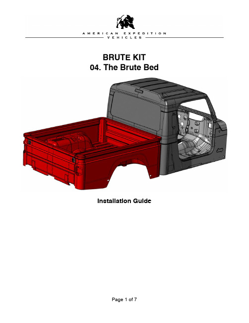
BRUTE KIT 04. The Brute BedInstallation GuidePLEASE READ BEFORE YOU STARTTO GUARANTEE A QUALITY INSTALLATION, WE RECOMMEND READING THESE INSTRUCTIONS THOROUGHLY BEFORE BEGINNING ANY WORK. THESE INSTRUCTIONS ASSUME A CERTAIN AMOUNT OF MECHANICAL ABILITY AND ARE NOT WRITTEN OR INTENDED FOR SOMEONE NOT FAMILIAR WITH AUTO BODY REPAIR.Required ToolsDrill Motor4” Angle GrinderTape MeasureAppropriate Safety Equipment Common Hand ToolsSpring Loaded Center Punch or Equivalent File or Die GrinderA. PAINTING THE BED AND TAILGATE ASSEMBLIESOVERVIEWThe Brute bed is delivered as an assembled unit requiring no fabrication. The bed will need to be prepared and painted. Preparation of the bed includes smoothing exterior spot welds and seam sealing all the seams.Minor assembly of the bed consists of:•Installation of the fender flares•Installation of the ground strap•Installation of an optional spray-in urethane bed liner.•Installation of the stock taillights.Minor assembly of the tailgate is required and involves:•Bolting the tailgate to the bed.•Installation the tailgate latches and bed support cables.•Installation of the license plate bracket.The Bed assembly, once painted will be mounted to the frame and aligned with the rest of the body. This process is easy but can be time consuming to achieve a perfect fit. We generally allow two hours for alignment and any shimming if required.INSTRUCTIONS1. Install the hinges to the tailgate using the supplied hinges and hardware provided in theBrute Hardware pack. The tailgate is now ready for paint prep and paint.2. Drill any required holes. If you are planning on drilling any holes and or trimming thewheel openings for the AEV Highline Body Kit, bed tie downs, or any other accessory,now is the time.3. Using the FUSOR 123 or equivalent catalyzed seam sealer, tape, seal and sand allexterior seams.4. Prepare all spot welded areas for a light skim coat of autobody filler. Block, prime, sealand paint per autobody collision repair standards. If you are planning on using a spray-inbed liner, there is no reason to paint the inside. We recommend bringing the spray-inliner up over the rails and down the outside approximately 5/8 to 3/4 inches to line up with the horizontal exterior seam in the corners of the bed.5. It is acceptable to seam seal the exterior seams on the front of the bed and not finish outthe spot welds.B. INSTALLATION OF THE BRUTE BEDOVERVIEWDO NOT MOUNT THE TAILGATE TO THE BED UNTIL THE BED HAS BEEN MOUNTED, AND THE ENTIRE BODY ALIGNED AND BOLTED DOWN INTO FINAL POSITION. INSTRUCTIONS1. Insert the six rubber bed mounts. Use the two supplied in the Brute Hardware pack alongwith the four rear most stock body mounts as shown.2. Place the bed onto the frame, be especially careful at the rear of the bed where it fitsaround the rear crossmember. Roughly align the unit by eye.3. Run a piece of heavy utility string along the bodyline on both sides of the vehicle from therear corner of the bed onto the door line and up as far as the cowl. This will allow you tostand at the front of the vehicle and “Gunsight” the bodyline down the side to align thecab and bed. This is a time consuming process as you will have to adjust the bed andthe closeout separately to achieve perfect results. We typically allow for two hours forthis process. Use a jack and block of wood to lift the rear of the cab if necessary. Youmay have to use large washers between the body mounts and the body in order to leveleverything out.4. Once you have everything in alignment, weld the rear body mounts to the cab. Bolt thebody mount and isolator to the body and weld in place.5. Install the 3” spacers into the middle body mounts. Tighten all body mounts.6. Install the Ground strap from the exhaust hanger bolt to the bed crossmember directlyabove the middle exhaust hanger.7. Install the latches and cables onto the tailgate. The inside portion of the latch must betrimmed approximately 0.5” in order to fit into the inner portion of the tailgate. Bolt thecables on so that the “ear” on the cable ends directs the cable to fold downward when thegate is closed. DO NOT OVERTIGHTEN THE CABLE BOLTS. THEY MUST BE ABLETO SWING FREELY.8. Install the rubber bumpers into the tailgate tabs on the bed.9. Bolt the tailgate to the bed using the supplied hardware and nut plates. Center thetailgate so that the gaps are even on both sides and the gate is level at the bodylines with the bed. Design gap on either side is 0.2”.10. Install the license plate bracket. Wire the LED light to the stock tailgate connectors fromthe CHMSL in the donor vehicle.11. Install the flares and taillights from the donor vehicle.COMMENTS OR QUESTIONS? American Expedition VehiclesPhone: 406.251.2100Email:************************ Website: 。