SAF引风机安装说明书(A)
引风机安装作业指导书

1 作业项目概况1.1 作业内容内蒙古达电四期2#炉配备两台AN40e6 ( v13+4°)型轴流引风机,风量为237.89×10⁴m3/h,风机风压5186Pa,风机转速585r/min,电动机功率4300KW,电压10KV。
风机主要结构:(1)转子(2)机壳(3)进气箱(4)可调导叶芯筒组件(5)扩压器(6)电机(7)大、小集流器(8)冷却风机系统1.2作业范围及主要工程量1.2.1 作业范围设备清点、引风机基础划线、清理、各部分结构组合安装、最后检查、验收。
1.2.2 主要工程量风机总重:67.795T(1)可调导叶组件:5.6 T (2)转动组重量:11.5 T (3)机壳重量:15.07 T(4)扩压器装配:15.4 T (5)进气箱装配:10.6 T1.3 相关专业的作业要求1.3.1 引风机过轨吊已安装完毕,并经负荷试验验收合格,办理签证后交付使用。
1.3.2 施工道路畅通,电源安装完毕,并具备使用条件。
1.3.3 各种安全设施都已齐全,并具备使用条件。
1.3.4 引风机基础经各质量工程部验收合格具备安装条件.并办理验收签证。
2 编制依据2.1 执行和引用的设计图纸及其说明2.1.1 引风机厂家技术图纸资料2.1.2 引风机安装说明书2.1.3 锅炉房辅助设备安装图(J0301)2.2 执行和引用的规程、规范及相关技术标准2.2.1 《电力建设安全工作规程》火力发电厂部分2.2.2 《电力建设施工及验收技术规范》锅炉机组篇DL/T5047-952.3 执行和引用的质量检验标准2.3.1《火力发电厂施工质量检验及评定标准》锅炉篇96版2.4 执行和引用的安全健康和环境管理的标准及已批准的相关文件2.4.1《电力建设安全健康与环境管理工作规定》2002-01-212.4.2 相关文件ISO14000环境标准及OHSAS18000职业安全卫生系列标准。
3 作业准备3.1 作业主要责任人、职责及应具备的条件3.1.1 作业主要责任人:专业公司经理、专责工程师、班长、技术员3.1.1.1 专业公司经理的职责:贯彻执行上级有关安全健康与环境保护的措施与规定,组织编制本专业公司安全健康与环境保护措施,经批准后组织实施。
1引风机安装作业指导书

编号:有限责任公司项目部作业指导书工程名称:作业项目名称:引风机安装编制单位:批准:年月日安全审核:年月日质量审核:年月日技术审核:年月日工地审核:年月日编制:年月日目录1 编制依据 (2)1.1编制依据 (2)1.2编制原则 (2)2 工程概况及工程量 (3)2.1工程概况: (3)2.2主要工作量: (3)3 作业前必须具备的条件和应做准备 (3)4 劳动力配置及职责权限 (4)5 机械及工器具的配备 (4)6 作业程序、方法和内容 (5)6.1施工方案 (5)6.2施工工艺流程 (5)6.3施工方法及要求 (5)7 作业过程中质量控制点、质量标准、检查验收和质量保证措施 (9)7.1质量目标 (9)7.2质量控制及质量通病预防 (9)7.3质量标准及要求 (10)8 作业的安全要求、危险源识别与控制、安全保证措施 (11)8.1作业的安全危害因素辨识和控制 (11)8.2环境条件 (12)8.3安全施工措施 (13)8.4文明施工及环境保护 (14)9 作业进度计划 (15)10 各种记录表样 (16)《电力工业锅炉压力容器监察规程》 DL 612-1996 (18)设备/材料开箱检验移交报告单 (19)设计变更汇总记录 (21)隐蔽工程验收记录 (22)性能验收记录 (25)1 编制依据1.1 编制依据1.1.1 《※※※有限公司☆☆☆机组锅炉烟气脱硫除尘系统改造项目》招标文件及技术协议。
1.1.2 签订的《※※※有限公司☆☆☆机组锅炉烟气脱硫除尘统改造项目总包合同》。
1.1.3 原国家电力公司颁布的《火力发电工程施工组织设计导则》,原国家电力公司颁布的《电力建设工程施工技术管理导则》。
国家电力公司《火电优质工程评选办法(2010年)版》,《火力发电厂基本建设工程启动及竣工验收规程》电建(1996)159号;《火电机组达标投产考核标准(2006年)版》。
1.1.4 国家和行业有关技术标准、规范、规程。
风力发电机安装使用说明书

青岛安华新源风电设备有限公司 Qingdao Anhua New Energy Equipment Co., Ltd.AH-20KW版本: 1.0青岛安华新源风电设备有限公司设计并生产 电话: (86-532) 82875373 电子邮箱: anhua@ 详情请登录网站 传真: (86-53 2)82100053是青岛安华新源风电设备有限公司在中华人民共和国的注册商标----------------------------------------------------------------------------------------------------------------------------------------------------1 地址:青岛市闽江路 172 号软件大厦 1706 室 电话:0086-532-82875373 邮编:266011 传真:0086-532-82100053 2/10/2009 Email: tianwutianali@青岛安华新源风电设备有限公司 Qingdao Anhua New Energy Equipment Co., Ltd.目录1. 用途----------------------------------------------------------------------------------4 2. 结构和主要技术性能-------------------------------------------------------------4技术参数-------------------------------------------------------------------------------------------4 功率曲线-------------------------------------------------------------------------------------------53. 结构特点----------------------------------------------------------------------------6 4. 准备工作----------------------------------------------------------------------------6 5. 整机组装----------------------------------------------------------------------------75.1 安装机舱-------------------------------------------------------------------------------------------7 5.2 安装尾舵-------------------------------------------------------------------------------------------8 5.3 安装风轮-------------------------------------------------------------------------------------------9 5.4 安装电动铰盘-------------------------------------------------------------------------------------10 5.5 组装塔杆--------------------------------------------------------------------------------------------106. 立杆-----------------------------------------------------------------------------------12 7. 电气连接-----------------------------------------------------------------------------17 8. 风力机保养--------------------------------------------------------------------------18 9. 故障排除-----------------------------------------------------------------------------18 附录 1:20kW15m 独立锥管塔杆基础--------------------------------------------21 附录 2:20kW15m 正四边形桁架塔杆基础--------------------------------------22 附录 3:20kW15m 拉索塔杆基础--------------------------------------------------23 附录 4:装箱清单----------------------------------------------------------------------24 附录 5:蓄电池蓄能、风、光、柴互补供电方式-------------------------------25 附录 6:向 AC380V/AC220V 用户网供电----------------------------------------26 附录 7:螺栓扭紧力矩(Nm)表---------------------------------------------------27----------------------------------------------------------------------------------------------------------------------------------------------------2 地址:青岛市闽江路 172 号软件大厦 1706 室 电话:0086-532-82875373 邮编:266011 传真:0086-532-82100053 2/10/2009 Email: tianwutianali@青岛安华新源风电设备有限公司 Qingdao Anhua New Energy Equipment Co., Ltd.----------------------------------------------------------------------------------------------------------------------------------------------------3 地址:青岛市闽江路 172 号软件大厦 1706 室 电话:0086-532-82875373 邮编:266011 传真:0086-532-82100053 2/10/2009 Email: tianwutianali@青岛安华新源风电设备有限公司 Qingdao Anhua New Energy Equipment Co., Ltd.1. 用 途利用风力发电,向蓄电池组充电,把储存的电能以直流和交流两种多制式电 源供给照明、家用电器、通讯设备和电动工具使用,还可以通过并网逆变器向 AC380/220V 国 家 电 网 馈 送 电 能 。
风机使用说明书
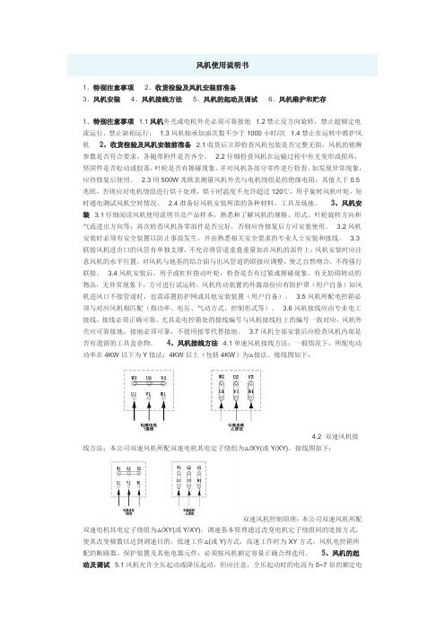
风机使用说明书1、特别注意事项2、收货检验及风机安装前准备3、风机安装4、风机接线方法5、风机的起动及调试6、风机维护和贮存1、特别注意事项1.1风机外壳或电机外壳必须可靠接地1.2禁止反方向旋转,禁止超额定电流运行,禁止缺相运行;1.3风机轴承加油次数不少于1000小时/次1.4禁止在运转中维护风机2、收货检验及风机安装前准备2.1收货后立即检查风机包装是否完整无损,风机的铭牌参数是否符合要求,各随带附件是否齐全。
2.2仔细检查风机在运输过程中有无变形或损坏,坚固件是否松动或胶落,叶轮是否有擦碰现象,并对风机各部分零件进行检查。
如发现异常现象,应待修复后使用。
2.3用500W兆欧表测量风机外壳与电机绕组是的绝缘电阻,其值大于0.5兆欧,否则应对电机绕组进行烘干处理,烘干时温度不允许超过120℃,用手旋转风机叶轮,短时通电测试风机空转情况。
2.4准备好风机安装所需的各种材料、工具及场地。
3、风机安装3.1仔细阅读风机使用说明书及产品样本,熟悉和了解风机的规格、形式、叶轮旋转方向和气流进出方向等;再次检查风机各零部件是否完好,否则应待修复后方可安装使用。
3.2风机安装时必须有安全装置以防止事故发生,并由熟悉相关安全要求的专业人士安装和接线。
3.3联接风机进出口的风管有单独支撑,不允许将管道重叠重量加在风机的部件上;风机安装时应注意风机的水平位置,对风机与地基的结合面与出风管道的联接应调整,使之自然吻合,不得强行联接。
3.4风机安装后,用手或杠杆拨动叶轮,检查是否有过紧或擦碰现象,有无妨碍转动的物品,无异常现象下,方可进行试运转,风机传动装置的外露部份应有防护罩(用户自备)如风机进风口不接管道时,也需添置防护网或其他安装装置(用户自备)。
3.5风机所配电控箱必须与对应风机相匹配(指功率、电压、气动方式、控制形式等)。
3.6风机接线应由专业电工接线,接线必须正确可靠,尤其是电控箱处的接线编号与风机接线柱上的编号一致对应,风机外壳应可靠接地,接地必须可靠,不能用接零代替接地。
引风机安装施工作业指导书(初版)(DOC)
锅炉专业》引风机安装》作业指导书目录1编制依据 (1)2作业任务 (1)3作业准备和作业环境条件 (1)4施工进度 (3)5作业方法及工艺要求 (4)6作业活动质量标准及检验要求 (14)7创优措施 (16)8强制性条文内容 (17)9 成品保护 (17)10 职业安全卫生及环境管理 (17)11绿色施工措施 (20)1 编制依据1.1 中华人民共和国安全生产法1.2 《电力建设安全工作规程》(火力发电厂部分)DL5009.1-20021.3 《电力建设施工质量验收及评价规程》第2部分(锅炉机组)DL/T5210.2-2009 1.4 《火力发电厂焊接技术规程》DL/T869—20121.5 《电力建设安全健康与环境管理工作规定》1.6 豪顿华工程有限公司ANN-2975/1700B型引风机安装使用说明书1.7 大唐呼图壁热电厂2×300MW机组工程质量标准及工艺要求1.8 大唐呼图壁热电厂2×300MW机组工程创优规划1.9 工程建设标准强制性条文(2006版)2.作业任务2.1工作概况大唐呼图壁热电厂2×300MW工程#2锅炉引风机由新疆电力设计院设计,豪顿华工程有限公司制造;引风机型号为ANN-2975/1700B型,#2锅炉共安装一台引风机。
该风机为轴流风机。
风机由电机驱动,从驱动端看,叶轮顺时针旋转。
ANN型风机配有一个转子,安装于布置在进气箱内的轴承箱上,转子位于机加工的叶轮机壳上。
引风机主要技术参数:型号 ANN-2975/1700B型叶轮直径 2975㎜轮毂直径 1700㎜风压 8585Pa转速: 997rpm电动机电压 6KV电动机功率 5600kw2.2 工作范围:引风机的安装主要包括:扩散器、调节驱动装置、旋转油封、液压调节管路、轮毂、叶片、叶轮机壳、进气箱、轴承组、联轴器、滑道、扩散器、引风机驱动电机等。
3 作业准备和作业环境条件3.1 作业人员的资格要求及劳动力组织3.1.1施工人员上岗前必须参加安全学习与培训,并经考试合格。
Altra-Air Sailfin 风扇安装指南说明书

ELECTRICAL INSTALLATION GUIDE ALTRA-AIR SAILFIN FANSubject to Changes Without Notification.All installation wiring must conform to your National Electrical Code and meet Local Codes. While we can’t guarantee it, we believe that using Envira-North Systems controls and following our instructions will result in an installation that meets those requirements. Code compliance is ultimately the installer’s and/or the user’s responsibility.TABLE OF CONTENTS (2)SAFETY PRECAUTIONS (2)Essential AIR FAN CONTROL INSTALLATION ..........................................3 - 7 Zone AIR FAN CONTROL INSTALLATION .............................................8 - 14 Command AIR FAN CONTROL INSTALLATION ...................................15 - 19All installations must be installed by a qualified person.Do not work on live equipment. Use of lock-out procedures is a must.IMPORTANT!The installation of a wind sensor is mandatory in agricultural installations. The installation of a wind sensor is mandatory in agricultural installations.VFD• Wall Mounted Variable Frequency Drive (VFD) Configuration • Minimal Distance Between VFD & HVLS Fan• One Per Fan RequiredREFERENCE ACRONYM KEYVFD - Variable Frequency DriveWIRE REQUIREMENTS• The size of the input and output wires depends on the length and current draw of the VFD and Motor • Use a continuous run of wires between the Motor and VFD (no splices or connections)• See ‘Power Requirements’ for current draw of VFD and MotorPOWER REQUIREMENTSINPUT 240VOUTPUT 240VINPUT 400VOUTPUT 400VINPUT 480VOUTPUT 480VINPUT 600VOUTPUT 600VVFD 1 Ph 3 Ph 3 Ph 3 Ph 3 Ph 3 Ph 3 Ph 3 Ph 3 Ph 1.0HP (.75 kW)8.8 A 5.0 A 4.2 A 2.9 A 2.4 A 2.5 A 2.1 A 2 A 1.7 A 1.5HP (1.1 kW)12.0 A 6.9 A 6.0 A 4.2 A 3.5 A 3.6 A 3.0 A N/A N/A 2.0HP (1.5 kW)13.3 A 8.1 A 7.0 A4.7 A 4.0 A4.1 A 3.5 A3.2 A 2.7 A170-264 VAC 48-62 Hz170-264 VAC 48-62 Hz340-440 VAC 48-62 Hz340-528 VAC 48-62 Hz425-660 VAC 48-62 HzA separate insulated ground must be provided to each VFD from the electrical panel.This will reduce the noise from being radiated in other equipment.This will reduce the noise from being radiated in other equipment. Motor is rated with an Insulation Class F;Ensure proper wiring is used as per current electrical codes.Ensure proper wiring is used as per current electrical codes. The above values are full-load current values.WIRING SCHEMATICFAN MOTORELECTRICAL PANELVFDMinimum 1’ (300mm)AC 1Ph (230V Model Only) or 3Ph Dry Industrial/Commercial Conduit, 1Ph = 2 wires + insulated ground 3Ph = 3 wires + insulated groundAC (PWM) 3Ph Dry Conduit(Inverter Duty, 3 wires +insulated ground)WIRE LOCATION• DO NOT RUN input and output power cables in the same conduit• DO NOT RUN control cables with any power cables in the same conduit• DO NOT RUN different fan’s output power cables in the same conduitYou may run different fans input (only) power cables in the same conduit.CABLE LENGTHThe cable distance between the Lenze AC Tech VFD and the Motor has changed. In all cases it has been reduced due to variable cable quality, variations in workmanship and changes in technology in the VFD.LOAD REACTOR ANDLOAD REACTOR AND d d V/V/d d T FILTERThe following table; the cable length includes vertical distances. There will be 3 different classes of distance having distance measurement, addition of load reactor or dV/dT filter and change in the horsepower rating of the VFD. In cases of adding either a load reactor or filter, the device has to be installed close to the VFD (within 6-10 feet) on the Load Side of the VFD.CABLE LENGTH BETWEEN THE LENZE AC TECH VFD AND MOTORNormal Length No Additional Device Required or Change in VFD HP230 VAC Max. 250’No HP Change460 VAC Max. 160’No HP Change600 VAC Max. 125’No HP ChangeAbove Normal Length Load Reactor Required (1 ½ or 3 % Impedance)230 VAC250’ - 400’No HP Change460 VAC160’ - 250’No HP Change600 VAC125’ - 160’No HP ChangeGreater Than Above Normal Length dV/dT Filter Required Plus Upsize VFD HP230 VAC Greater than 400’ & lessthan 1000’+1 HP460 VAC Greater than 250’ & lessthan 1000’+1 HP(*1) 600 VAC Greater than 160’ & lessthan 1000’+1 HPThe filter and load reactor can operate at either 50Hz or 60Hz.(*1) When using 600VAC Lenze AC Tech VFD, special care will have to be taken as VFD manufacturers have noted that excessive reflective voltages are generated due to the distance. The voltages may shorten the life expectancy of the motors and VFDs and may cause bearing failures if not dealt with according to the instructions above.WIRE CONNECTIONS (VFD)Input Power• Single phase (1Ph) use L1 - L2 + PE (Ground)• Three phase (3Ph) use L1 - L2 - L3 + PE (Ground)WIRE CONNECTIONS (MOTOR)The thermal protection wires in the junction box of the Nord motor are not to be used unless otherwise directed. The Variable Frequency Drive provides the over temperature and overload protection.T1 T2 T3 230 VAC From VFD T1 T2 T3460 VACFrom VFDT1 T2 T3230 VACFrom VFDT1 T2 T3400 VACFrom VFDOPERATING INSTRUCTIONSTO START (Press):TO STOP (Press):TO CHANGE SPEED (Press):TO CHANGE ROTATION (Press):(Then Press):EssentialAIR Keypad•Fan Mounted VFD• One ZoneAir Control Per Fan Required• Package Includes Mounting Plate + Wiring Harness • Designed to Provide a Single Control for Multiple Fans •Requires Additional ControlsVFDMount PlateWiring HarnessREFERENCE ACRONYM KEY VFD - Variable Frequency Drive LVC - Low Voltage Control TFD - Temperature ControlWIRE REQUIREMENTS• The size of the input and output wires depends on the length and current draw of the VFD and Motor• Use a continuous run of wires between the Motor and VFD (no splices or connections)• See ‘Power Requirements’ for current draw of VFD and MotorPOWER REQUIREMENTSINPUT 240VOUTPUT 240VINPUT 400VOUTPUT 400VINPUT 480VOUTPUT 480VINPUT 600VOUTPUT 600VVFD 1 Ph 3 Ph 3 Ph 3 Ph 3 Ph 3 Ph 3 Ph 3 Ph 3 Ph 1.0HP (.75 kW)8.8 A 5.0 A 4.2 A 2.9 A 2.4 A 2.5 A 2.1 A 2 A 1.7 A 1.5HP (1.1 kW)12.0 A 6.9 A 6.0 A 4.2 A 3.5 A 3.6 A 3.0 A N/A N/A 2.0HP (1.5 kW)13.3 A 8.1 A 7.0 A4.7 A 4.0 A4.1 A 3.5 A3.2 A 2.7 A170-264 VAC 48-62 Hz170-264 VAC 48-62 Hz340-440 VAC 48-62 Hz340-528 VAC 48-62 Hz425-660 VAC 48-62 HzA separate insulated ground must be provided to each VFD from the electrical panel.This will reduce the noise from being radiated in other equipment.This will reduce the noise from being radiated in other equipment. Motor is rated with an Insulation Class F;Ensure proper wiring is used as per current electrical codes.Ensure proper wiring is used as per current electrical codes. The above values are full-load current values.WIRING SCHEMATICFAN MOTOR ELECTRICAL PANELVFDMinimum 1’ (300mm)AC 1Ph (230V Model Only) or 3Ph Dry Industrial/Commercial Conduit, 1Ph = 2 wires + insulated ground 3Ph = 3 wires + insulated groundAC (PWM) 3Ph Dry Conduit(Industrial/Commercial) (Inverter Duty, 3 wires +insulated ground)Wet/Agricultural EMT Conduit 220 VAC, 1PH (2 wires + Ground)See Wind Sensor Manual For Installation DetailsTEMPERATURE CONTROLLOW VOLTAGE CONTROLWIND SENSORWIRE LOCATION• DO NOT RUN input and output power cables in the same conduit• DO NOT RUN control cables with any power cables in the same conduit• DO NOT RUN different fan’s output power cables in the same conduitYou may run different fan’s input (only) power cables in the same conduit.CABLE LENGTHThe cable distance between the Lenze AC Tech VFD and the Motor has changed. In all cases it has been reduced due to variable cable quality, variations in workmanship and changes in technology in the VFD.LOAD REACTOR ANDLOAD REACTOR AND d d V/V/d d T FILTERThe following table; the cable length includes vertical distances. There will be 3 different classes of distance having distance measurement, addition of load reactor or dV/dT filter and change in the horsepower rating of the VFD. In cases of adding either a load reactor or filter, the device has to be installed close to the VFD (within 6-10 feet) on the Load Side of the VFD.CABLE LENGTH BETWEEN THE LENZE AC TECH VFD AND MOTORNormal Length No Additional Device Required or Change in VFD HP230 VAC Max. 250’No HP Change460 VAC Max. 160’No HP Change600 VAC Max. 125’No HP ChangeAbove Normal Length Load Reactor Required (1 ½ or 3 % Impedance)230 VAC250’ - 400’No HP Change460 VAC160’ - 250’No HP Change600 VAC125’ - 160’No HP ChangeGreater Than Above Normal Length dV/dT Filter Required Plus Upsize VFD HP230 VAC Greater than 400’ & lessthan 1000’+1 HP460 VAC Greater than 250’ & lessthan 1000’+1 HP(*1) 600 VAC Greater than 160’ & lessthan 1000’+1 HPThe filter and load reactor can operate at either 50Hz or 60Hz.(*1) When using 600VAC Lenze AC Tech VFD, special care will have to be taken as VFD manufacturers have noted that excessive reflective voltages are generated due to the distance. The voltages may shorten the life expectancy of the motors and VFDs and may cause bearing failures if not dealt with according to the instructions above.WIRE CONNECTIONS (VFD)Input Power• Single phase (1Ph) use L1 - L2 + PE (Ground)• Three phase (3Ph) use L1 - L2 - L3 + PE (Ground)WIRE CONNECTIONS (MOTOR)The thermal protection wires in the junction box of the Nord motor are not to be used unless otherwise directed. The Variable Frequency Drive provides the over temperature and overload protection.T1 T2 T3 230 VAC From VFD T1 T2 T3460 VACFrom VFDT1 T2 T3230 VACFrom VFDT1 T2 T3400 VACFrom VFD1 2 5 6 25 4 11 13A 13B13C 14 30 16 171 2 5 6 25 4 11 13A 13B13C 14 30 16 171 2 5 6 25 4 11 13A 13B13C 14 30 16 17Terminal 6 notconnected between 2nd and 3rd VFDTerminal 6 notconnected between 1st and 2nd VFD3rd VFD 2nd VFD 1st VFD IMPORTANTAll VFDs must have their individual power turned on for the fans to operate.power turned on for the fans to operate. •WIRE CONNECTIONS (LVC)M a x i m u m d i s t a n c e b e t w e e n t h e L V C a n d t h e L A S T o r 7t h V F Di s 700 f e e t (214m e t e r s )Low Voltage Control ConnectionsSW1Shown in Manual PositionSW1-A0V AIN 10VEmergency Stop NCFWD OFF REV2 5 6 4 13B 13A 17 Wires to VFD (18AWG Shielded)4 Wires to TFD-1 (18AWG Shielded)Temperature ControlConnections240VAC 1PHTemp Probe+- +-PRB 0-10Rel 1OPERATING INSTRUCTIONS (LVC)1. DO NOT TURN OFF THE FAN WHILE IN MOTION USING A DISCONNECT SWITCH.2. Make sure the toggle switch labelled “TFD-1 / Manual” switch is in the ‘MANUAL’ position.3. Use the speed potentiometer to adjust the fan’s speed4. Always use the Red Stop button (on the right of the Low Voltage Controller) to turn off or stop the fan.5. To reverse the direction of the fan while in motion, use the toggle switch labelled “Forward / Reverse.”SETUP OF TFD TEMPERATURE CONTROLLERTo adjust the TFD:• Rotate the Selector dial to position (1) Set Point• Rotate the Adjustor dial to desired set point temperature (Example 20°C)• Rotate the Selector dial to position (2) Modulation Band• Rotate the Adjustor dial to desired modulation band (Example 10°C)• Rotate the Selector dial to position (3) Minimum Ventilation Off• Rotate the Adjustor dial to desired minimum (Example 5°C)In the examples above, from start-up, the fan will start to turn only if the interior temperature reaches 20°C. The speed that will be indicated on the fan controller should be approximately 27%. As the temperature rises in the building, the fan will increase speed until the temperature reaches the end of the modulation band. At 30C (set point + modulation band) the fan will be at its maximum (100%) speed.As the temperature decreases the speed will decrease until you reach the set point (20°C). At that point the speed will be at its minimum. As the temperature decreases below the set point, the fan will continue to operate at its minimum rate until you reach 15°C (set point minus the minimum ventilation off). Below this point of 15°C the fan will stop and will stay in the off condition until the temperature rises to the set point – minimum off (15°C) and then the cycle repeats itself.The minimum speed has been programmed to 15 Hz or 27%. DO NOT lower it pass this limit otherwise your warranty will be void. Lowering the speed below 15 Hz or 27% will cause the motor to overheat because the motor will not draw enough air to cool down at these low speeds.OPERATING INSTRUCTIONS (LVC + TFD)1. DO NOT TURN OFF THE FAN WHILE IN MOTION USING A DISCONNECT SWITCH.2. Make sure the toggle switch labelled “TFD-1 / Manual” switch is in the ‘TFD-1’ position.3. Always use the Red Stop button (on the right of the Low Voltage Controller) to turn off or stop the fan.4. To reverse the direction of the fan while in motion, use the toggle switch labelled “Forward / Reverse.”• Fan Mounted VFD• One CommandAIR Control Per Fan Required• Package Includes Mounting Plate + Wiring Harness + Control Wire • and Remote Keypad• Provides Remote Troubleshooting for Fan Mounted VFD • User Friendly, Simplifed Installation and OperationVFDMount PlateWiringHarnessRemote Keypad 100’ (30.48m) CAT 5 CableREFERENCE ACRONYM KEYVFD - Variable Frequency DriveWIRE REQUIREMENTS• The size of the input and output wires depends on the length and current draw of the VFD and Motor • Use a continuous run of wires between the Motor and VFD (no splices or connections)• See ‘Power Requirements’ for current draw of VFD and MotorPOWER REQUIREMENTSINPUT 240VOUTPUT 240VINPUT 400VOUTPUT 400VINPUT 480VOUTPUT 480VINPUT 600VOUTPUT 600VVFD 1 Ph 3 Ph 3 Ph 3 Ph 3 Ph 3 Ph 3 Ph 3 Ph 3 Ph 1.0HP (.75 kW)8.8 A 5.0 A 4.2 A 2.9 A 2.4 A 2.5 A 2.1 A 2 A 1.7 A 1.5HP (1.1 kW)12.0 A 6.9 A 6.0 A 4.2 A 3.5 A 3.6 A 3.0 A N/A N/A 2.0HP (1.5 kW)13.3 A 8.1 A 7.0 A4.7 A 4.0 A4.1 A 3.5 A3.2 A 2.7 A170-264 VAC 48-62 Hz170-264 VAC 48-62 Hz340-440 VAC 48-62 Hz340-528 VAC 48-62 Hz425-660 VAC 48-62 HzA separate insulated ground must be provided to each VFD from the electrical panel.This will reduce the noise from being radiated in other equipment.This will reduce the noise from being radiated in other equipment. Motor is rated with an Insulation Class F;Ensure proper wiring is used as per current electrical codes.Ensure proper wiring is used as per current electrical codes. The above values are full-load current values.WIRING SCHEMATICFAN MOTORELECTRICAL PANELVFDMinimum 1’ (300mm)AC 1Ph (230V Model Only) or 3Ph Dry Industrial/Commercial Conduit, 1Ph = 2 wires + insulated ground 3Ph = 3 wires + insulated groundAC (PWM) 3Ph Dry Conduit(Inverter Duty, 3 wires +insulated ground)Disconnect Switch (not provided)REMOTE KEYPADCAT-5 Cable ProvidedWIRE LOCATION• DO NOT RUN input and output power cables in the same conduit• DO NOT RUN control cables with any power cables in the same conduit• DO NOT RUN different fan’s output power cables in the same conduitYou may run different fans input (only) power cables in the same conduit.CABLE LENGTHThe cable distance between the Lenze AC Tech VFD and the Motor has changed. In all cases it has been reduced due to variable cable quality, variations in workmanship and changes in technology in the VFD.LOAD REACTOR ANDLOAD REACTOR AND d d V/V/d d T FILTERThe following table; the cable length includes vertical distances. There will be 3 different classes of distance having distance measurement, addition of load reactor or dV/dT filter and change in the horsepower rating of the VFD. In cases of adding either a load reactor or filter, the device has to be installed close to the VFD (within 6-10 feet) on the Load Side of the VFD.CABLE LENGTH BETWEEN THE LENZE AC TECH VFD AND MOTORNormal Length No Additional Device Required or Change in VFD HP230 VAC Max. 250’No HP Change460 VAC Max. 160’No HP Change600 VAC Max. 125’No HP ChangeAbove Normal Length Load Reactor Required (1 ½ or 3 % Impedance)230 VAC250’ - 400’No HP Change460 VAC160’ - 250’No HP Change600 VAC125’ - 160’No HP ChangeGreater Than Above Normal Length dV/dT Filter Required Plus Upsize VFD HP230 VAC Greater than 400’ & lessthan 1000’+1 HP460 VAC Greater than 250’ & lessthan 1000’+1 HP(*1) 600 VAC Greater than 160’ & lessthan 1000’+1 HPThe filter and load reactor can operate at either 50Hz or 60Hz.(*1) When using 600VAC Lenze AC Tech VFD, special care will have to be taken as VFD manufacturers have noted that excessive reflective voltages are generated due to the distance. The voltages may shorten the life expectancy of the motors and VFDs and may cause bearing failures if not dealt with according to the instructions above.WIRE CONNECTIONS (VFD)Input Power• Single phase (1Ph) use L1 - L2 + PE (Ground)• Three phase (3Ph) use L1 - L2 - L3 + PE (Ground)WIRE CONNECTIONS (MOTOR)The thermal protection wires in the junction box of the Nord motor are not to be used unless otherwise directed. The Variable Frequency Drive provides the over temperature and overload protection.T1 T2 T3 230 VAC From VFD T1 T2 T3460 VACFrom VFDT1 T2 T3230 VACFrom VFDT1 T2 T3400 VACFrom VFDOPERATING INSTRUCTIONSTO START (Press):TO STOP (Press):TO CHANGE SPEED (Press):TO CHANGE ROTATION (Press):(Then Press):KeypadTel: 1-519-527-2198 Fax: 1-519-527-2560 Toll Free: 1-886-771-7766**********************139 Sparling St. P.O Box 668Seaforth, OntarioCanada N0K 1W0。
风机安装指导说明书:

风机安装调试使用说明指导书西安巨龙风机有限公司一、风机的安装(一)安装前的施工准备:1)在安装前首先应准备好安装用材料及工具,并对风机各部件进行全面检查,机件是否完整、叶轮与标示的旋转方向是否一致、各部件联接是否紧固;根据文件核对叶轮、机壳和其它部件的主要安装尺寸是否符合设计要求等。
2)基础的验收和放线:首先,检查地基的外形尺寸;基础划线,以主厂房建筑基点或设备纵横中心线为基准,测得基础纵横主中心线偏差,中心线距离偏差,;基层表面不得有空腔、疏松、夹层和脏杂物;采用拉钢丝挂线锤法对基础进行检验和放线。
3)垫铁的安装:凿平地基,放置地脚螺栓、布置垫铁,厚的放下面,斜垫铁应成对使用;找正后应焊牢、不许松动;平垫铁采用座法安装。
4)风机的准备:清理干净各组件,注意检查机壳,壳内不应掉入和遗留工具和杂在一些结合面上为了防止生锈减少拆卸困难,将半联轴器在电机上。
(二)风机的就位与找正:1)、机壳下半部粗定位:将风机壳体下半部分放在基础上,同时预紧还应校正机壳横向水平度,符合要求后初步固定地脚螺栓.注意安装标记,就位前注意区分与进出口风管的关系、叶轮旋向等.2)、安装进气室,将下半部分螺栓预紧后,拆掉上半部分;安装密封元件,将轴封的下半部分与壳体连接,其端面应与机壳帖合良好。
3)、轴承下瓦安装:下轴瓦、轴承座、轴承盖安装时应使轴瓦背与轴承座孔接触良好,并且要求接触面积均匀,不允许下瓦底部与两侧出现间隙,一旦下瓦两侧有间隙,使轴瓦承受到压强增大,就导致很快磨损。
4)、转子安装:将进风口口环部分认准方向套进叶轮中,把转子吊平后徐徐放下,避免与其它部件碰闯,使转子吊入预定位置。
5)、风机转子找平、找正:转子重要部位的跳动检查:转子的中部和两端、叶轮的进口圈和联轴器等部位的径向跳动,轴径推力盘和联轴器端面等部位的轴向跳动,作记录(应有角度和数值两项内容)转子在位置确定后,应把转子相对于轴承座的位置值(径向和轴向)记录下来,以供检修时参考。
风机安装作业指导书
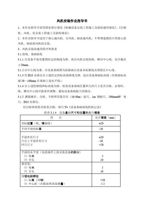
风机安装作业指导书1、本作业指导书采用国家现行规范《机械设备安装工程施工及验收通用规范》、《压缩机、风机、泵安装工程施工及验收规范》。
2、本作业指导书适用于离心通风机、引风机、轴流通风机,不带增速器的小型离心鼓风机、轴流鼓风机的安装。
3、风机安装的通用程序和要求3.1放线、基础验收3.1.1以设备平面布置图给定的轴线为准,放出风机安装的纵、横向中心线,允许偏差±20mm。
3.l .2以中心线为难,以设备基础图为依据画出设备各轮廓线及预留孔中心线。
3.1.3用DS3水准仪以土建给定的标高基准线为准,划出设备基础标高线(用基础标高减50—100mm在基础上划水平线)。
3.1.4以上述轮廓线和标高线为准,检查设备基础位置和几何尺寸是否合格。
必要时,纵、横向中心线可做某些调整,避免设备基础做大的修改。
3.1.5测量操作、自检、专检所用量具有(10-30m)盘尺,1m钢板尺,500mm90°角尺,DS3水准仪。
经自检和质检员检查合格,填写T4《设备基础放线检验记录》附表3.1.4 设备基础尺寸和位置的允许偏差3.2设备开箱检查3.2.1清点零、部件及配套件,应齐全并无损坏。
3.2.2核对机壳、叶轮和其他主要尺寸,应与设计要求相符合。
3.2.3风机进、出口方向应与设计相符,叶轮旋转方向和定子导流叶片的导流方向应符合设备技术文件的规定。
3.2.4检查风机外露部位及加工面应无锈蚀,风机各部位无变形及损坏。
开箱应有质检员和甲方代表在场,开箱检查后应填写S1《设备开箱检查验收记录》。
3.3设备就位、粗平、灌浆3.3.1风机的搬运和吊装应注意下列问题:a.整体出厂的风机搬运和吊装时,绳索不得捆缚在转子和机壳上盖或轴承上盖的吊耳上。
b.解体出厂的风机的捆缚不得损伤机件表面,转子和齿轮轴颈、测振部位不应做为捆缚部位,转子和机壳的吊装应保持水平。
c.当风机内壳涂有保护层时,应妥善保护,不得损伤。
d.转子和齿轮不得在地上滚动。
- 1、下载文档前请自行甄别文档内容的完整性,平台不提供额外的编辑、内容补充、找答案等附加服务。
- 2、"仅部分预览"的文档,不可在线预览部分如存在完整性等问题,可反馈申请退款(可完整预览的文档不适用该条件!)。
- 3、如文档侵犯您的权益,请联系客服反馈,我们会尽快为您处理(人工客服工作时间:9:00-18:30)。
动叶可调轴流引风机产品安装和使用说明书
(A本)
工程号:(2013-078)
编制: 朱婷婷
校对: 季瑛
审核: 王冲强
上海鼓风机厂有限公司
二○一三年四月
序号内容
1风机技术参数
1.1一般资料
1.2机械参数
1.3风机起动力矩
1.4风机特性曲线
2转子图和总图汇总的拧紧力矩
3联轴器的参数
4图样清单
5通过说明书B本“风机现场维护”补充内容6风机找正允许误差
7隔声包覆层结构示意图
1 风机技术参数
1.1 一般资料
风机型号SAF31.5-17-2
工程号 2013-078
合同号
建造年份 2013年
名称国投哈密发电有限公司一期2x660MW工程
安装地点国投哈密发电有限公司一期2x660MW工程工地
工况 风量 Q 风机总压升P介质密度 效率 转速 轴功率 电机功率 m3/s Pa Kg/m3 % r/min KW KW
T.B 683.00 9496 0.7300 86.60990 7252
7700 BMCR 598.00 8055 0.7660 87.419905361
1.2 机械参数
机壳直径φ3162
轮毂直径φ1678
叶轮级数 2
叶型14DA14
叶片数28
叶片材料15MnV
叶片和叶柄的连接高强度螺栓
液压缸径和行程φ415/H100MET
叶片调节范围-35o ~+15o
本工程使用415/100液压缸,现场可根据实际情况调整油压,但不得超过最大允许油压3MPa
风机机壳内径和叶片外径间的间隙:应符合JB/T4362-1999标准,其值为
4.7mm~6.3mm(叶片在最小安装角位置)
(叶片在关闭位置)
1.3风机起动力矩
风机转速 n = 990 r/min
转动惯量 J = 0.25GD2 = 3388 kgm2
风机功率(在最大工况) N= 7252 kw
风机扭矩(在最大工况) M= 69956 N.m
= 13000 N
电机轴端径向力 F
R
电机轴端轴向力 F
= 11700 N
A
电机功率 Ne = 7700 kw 从电机轴伸端看电机转向为顺时针旋转,风机转向为逆时针。
1.4风机特性曲线
风机型号 SAF31.5-17-2
用户国投哈密发电有限公司一期2x660MW工程工程号 2013-078
合同号
风机转速 990 r/min
2 转子图和总图汇总的拧紧力矩
件号拧紧力矩(Nm)名称
11.55 1120 轴承箱螺母M190X3
11.80 455 轴承箱与机壳连接螺钉M20X130
13.81 776 叶片螺钉M24x2x65
14.54 988 调节杆拧紧螺栓M24X120
16.14 2744 联轴器与传动盖连接螺栓M36X100
19.36 94 液压缸与推盘连接螺钉M12x70
19.34 231 调节环推盘与调节环连接螺钉M16x70 19.35 231 推盘与调节环连接螺钉M16x50
19.37 231 推盘与调节环连接螺钉M16x70
19.46 455 推盘与推杆连接螺钉M20x65
19.71 231 液压支承体与液压缸连接螺钉M12x30
19.74 1568 连接盖与支承环连接螺钉M30x70
19.76 455 液压支承体、连接盖与导向环连接螺钉M20x90
19.77 455 传动盖、连接盖与导向环连接螺钉M20x90
26.11.05 2744 中间轴连接螺钉M36X95
51.31.17 559 机壳与整流导叶环连接螺栓M24X100
51.39.03 1137 机壳与中分面连接螺栓M30X130
69.51 1900 机壳和整流导叶环地脚螺栓M56
69.52+69.55 750 进气箱和扩压器地脚螺钉M36x800
69.29 1600 电动机地脚螺钉M56x1500
注意:在拧紧至上述规定力矩后将螺母倒转(旋松)1/4圈
3.联轴器的参数
联轴器规格 联轴器法兰
直径 (mm)
开 口
Y (mm)
每一端面容许位移 轴向刚度
Ca
(N/MM)
±a1max
(mm)
±r1max
(mm)
01Form8001 φ690 43.5 5 12.1 975 03Form8001 φ690 43.5 5 12.1 975
4.图样清单
名 称 图 号
引风机总装图 S1GA5761
转子 S0GA3869(借2012-052) 引风机液压油管路 1TY0328(TY041-08)
引风机轴承箱油管路 0TY0833(TY057-08)
温度和防喘振装置 1TY0228(TY045-06)
进气膨胀节 1TY0020(TY026-06)
排气膨胀节 1TY0041(TY027-06)
双围带 1TY0298(TY032A-06)
叶片指示和调节机构 1TY0165(TY044-06)
5.通过说明书B本“风机现场维护”补充内容
若风机安装于沿海地区,为避免风机停机后因受含盐(雾)空气的侵蚀,可能造成动叶片旋转不灵活,要求用户在停机期间,每日将风机动叶片调节机构操作运转一次(叶片角度全行程范围)。