AT气动执行器说明书 欧德隆自控阀门
Omega流动控制三端阀门说明书

a brass body. Manual override is
SV-1502
standard. Other features include a quick-exhaust design, Buna-N seal, and temperature range of
-10 to 90°C (14 to 194°F). This
2Operating with less than 7 psi pressure will yield unpredictable flow characteristics.
3Maximum pressure for UL-listed valves is 170 psi.
Comes complete with operator’s manual.
SV-1502 shown larger than actual size.
To ONrOdeRrMALLY OPEN
B
Normally Closed
Normally Open
Model No.
Model No.
Port Connections
(NPT)
Orifice
P, A, B
R
Cv1
Diameter
Pressure Range2
(psi)
SV-1502 SV-1503
—
— SV-1513
P R SV-1514
3⁄8
3⁄4
2.7
7⁄16"
7 to 2303
1⁄2
3⁄4
3.0
7⁄16"
7 to 2303
3⁄4
1
7.7
3⁄4"
ACTUATECH气动执行器说明书

INSTRUCTION MANUALPart turn pneumatic actuatorwith Manual Override-Complete aluminium protection versionGDV60 - GDV3840 GSV30 – GSV19201)GENERAL FEATURES………………………………………………………………………………………………..pg.32)DATASHEET……………………………………………………………………………………………..pg.43)FUNCTIONAL DESCRIPTION……………………………………………..………….…………………….……………pg.54)DANGERS……….………………………………………………………………………………………..pg.75)PART DESCRIPTION……………..………………………………………………………….………………….pg.86)TRUOBLESHOOTING ………………………………………..…………………...…………………….pg.97)DISPOSAL…….………………...………………………………………………………..…………….....pg.9Environmentally friendly handling of the product.1)GENERAL FEATURES ••••••••••••••••••••••••••••••••••••••••••••••••••••••••••••••••••••••••••••••••••••••••••••••••••Actuatech manufacture a manual handwheel override for a wide range of part turn pneumatic actuators.The actuators with manual override are available on Double Acting “GDV” and Spring Return “GSV” versions.- The principle of the manual handwheel override application is to provide the possibility to open and close the valve connected to the actuator when this operation can’t be done with remote control.- Actuatech manual override actuator is itself equipped with an handwheel for manual operations and it doesn’t need any added declutchable gear box. This solution guarantees a compact size and a more light system on the valve.- When the actuator is manual operated it can be locked in Open/Closed position.- Actuator versions for low temperature and high temperature applications allow to operate respectively until temperatures of -50°C and +150°C, thanks to proper kind of lubrication and material for the gaskets.The maintenance should be done by Actuatech trained personnel only.This instruction manual contains important information regarding the Actuatech manual override actuator operation, installation, maintenance and storage.Please read carefully before installation and keep it in a safe place for further reference.Modification reserved. Rev.date 04/2018. No guarantee for accuracy. Older data sheets are invalid 2)DATASHEET•••••••••••••••••••••••••••••••••••••••••••••••••••••••••••••••••••••••••••••••••••••••••••••••••• DOUBLEACTINGNOMINALTORQUE (Nm)ISOFLANGESQUAREØHANDWEELRim pull forces ( N )To obtain thenominal torqueWeight( Kg )Teorical n° of turnsto close / openstarting from theneutral positionA B C DGDV60 60 F05-F07 14 180 19.3 2.8 11 - 99 263.3 137.6 GDV106 106 F05-F07 17 180 27.8 4 13 - 118.5 279.3 154.8 GDV120 120 F05-F07 17 180 33.8 4.5 14 - 122.1 288.4 163.9 GDV180 180 F07-F10 22 220 44.1 6 16 - 144.9 338.1 183.5 GDV240 240 F07-F10 22 220 54.5 8 18 - 156.8 353.7 199.1 GDV360 360 F07-F10 22 300 67.5 10.2 15 - 169.6 398 220.8 GDV480 480 F10-F12 27 300 83.3 13.2 16 - 193.8 440.6 236.4 GDV720 720 F10-F12 27 350 108.8 17.8 19 - 216.6 503.5 282.3GDV960 960 F10-F12 /F1436 350 128.6 23.8 20 - 239.7 518.3 297.1 GDV1440 1440 F12 / F14 36 400 133.5 33.6 25 - 283.5 636.4 365.6GDV1920 1920 F12-F16 /F1446 400 162.5 43 26 - 300.4 653.7 382.9 GDV3840 3840 F16 46 575 243.5 75 30 - 353.3 890.2 537.5SIMPLEACTINGNOMINALTORQUE (Nm)ISOFLANGESQUAREØHANDWEELRim pull forces ( N )To obtain thenominal torqueWeight( Kg )Teorical n° of turnsto close / openstarting from theneutral positionA B C DGSV30 30 F05-F07 14 180 19.3 3.2 11 129.4 - 263.3 137.6 GSV053 53 F05-F07 17 180 27.8 4.5 13 152.1 - 279.3 154.8 GSV060 60 F05-F07 17 180 33.8 4.5 14 169.3 - 288.4 163.9 GSV090 90 F07-F10 22 220 44.1 6.8 16 196.8 - 338.1 183.5 GSV120 120 F07-F10 22 220 54.5 9 18 204.8 - 353.7 199.1 GSV180 180 F07-F10 22 300 67.5 11.7 15 237 - 398 220.8 GSV240 240 F10-F12 27 300 83.3 15.2 16 260.2 - 440.6 236.4 GSV360 360 F10-F12 27 350 108.8 19.5 19 306.6 - 503.5 282.3GSV480 480 F10-F12 /F1436 350 128.6 28.1 20 324.1 - 518.3 297.1GSV720 720 F12 / F14 36 400 133.5 38.8 25 399 - 636.4 365.6GSV960 960 F12-F16 /F1446 400 162.5 50.6 26 414 - 653.7 382.9GSV1920 1920 F16 46 575 243.5 91 30 509 - 890.2 537.5 All the dimensions are in mm, for missing data see standard catalogue .Modification reserved. Rev.date 04/2018. No guarantee for accuracy. Older data sheets are invalid3) FUNCTIONAL DESCRIPTION •••••••••••••••••••••••••••••••••••••••••••••••••••••••••••••••••••••••••••••••••••••••••••••••••• NB: PRIOR TO MANUAL OVERRIDE OPERATE, ENSURE THAT THE ACTUATOR IS FREE FROM PRESSURE.1.Remove the cap to ensure there is no pressure in the actuator2.Engage the manual override and operate as required3.Disconnect the manual override (neutral position)*for standard actuators.TO CLOSE THE VALVETo close the valve turn the wheel in clockwise direction*.TO OPEN THE VALVETo open the valve turn the wheel in counterclockwise direction.* NB: Before commissioning to ensure proper disengagement, perform an ON-OFF maneuver of the actuatorModification reserved. Rev.date 04/2018. No guarantee for accuracy. Older data sheets are invalidNB: WHEN THE ACTUATOR HAS BEEN MANUALLY OPERATED, RETURN TO THE NEUTRAL POSITION PRIOR TO START NORMAL OPERATIONS.NEUTRAL POSITIONWith the screw in neutral position the piston can move freely and the actuator can be driven pneumatically. MANUAL OPERATION GDV : The handwheel turned counter clockwise, pushes the screw and piston inwards. The valve opens. GSV : The handwheel turned clockwise pushes the screw and piston inwards. The valve closes.MANUAL OPERATIONGDV : When the handwheel is turned clockwise, the screwand piston are drawn outwards. The valve closes. GSV : When the handwheel is turned counter clockwise, the screw and the piston are drawn outwards. The valve opens.Modification reserved. Rev.date 04/2018. No guarantee for accuracy. Older data sheets are invalid4)WARNINGS •••••••••••••••••••••••••••••••••••••••••••••••••••••••••••••••••••••••••••••••••••••••••••••••••• a) Don’t disassemble, compressed spring inside.b) Don’t use levers or bars.c) Don’t use the handwheel to lift the actuator.NB:Manual override is not recommended for safety related applications (SIL) as bypass of a security function. In this application, to prevent an unauthorized use, the manual override is provided with a locking device.Modification reserved. Rev.date 04/2018. No guarantee for accuracy. Older data sheets are invalid5)PART DESCRIPTION ••••••••••••••••••••••••••••••••••••••••••••••••••••••••••••••••••••••••••••••••••••••••••••••••••NB: In the case of actuator low or high temperature the pistons and the material of the O ring are different from the standard actuator.Modification reserved. Rev.date 04/2018. No guarantee for accuracy. Older data sheets are invalid6)TROUBLESHOOTING •••••••••••••••••••••••••••••••••••••••••••••••••••••••••••••••••••••••••••••••••••••••••••••••••• POTENTIAL EFFECT OFFAILUREPOTENTIAL CAUSE OF FAILURE SOLUTION Difficult manual operationsBlocked valve Repair or replace the valvePresence of particles inside the actuator due toan incorrect filtration of the airVerify the condition of the supply airand contact ActuatechThe actuator is pressurized Remove supply air7)DISPOSAL •••••••••••••••••••••••••••••••••••••••••••••••••••••••••••••••••••••••••••••••••••••••••••••••••• Our products are designed so that when they are at the end of their life cycle they can be completely disassembled, separating the different materials for the proper disposal and/or recovery. All materials have been selected in order to ensure minimal environmental impact, health and safety of personnel during their installation and maintenance, provided that, during use, they are not contaminated by hazardous substances.The personnel in charge of the product disposal/recovery, must be qualified and equipped with appropriate personal protective equipment (PPE), according to the product size and the type of service for which the device was intended. The management of waste generated during the installation, maintenance or due to the product disposal, is governed by the rules in force in the country where the product is installed, in any case, the following are general guidelines:- The metal components (aluminum/steel) can be restored as raw material;- Seals/sealing elements as contaminated by fluids from other materials and lubrication,must be disposed of.- The packaging materials that come with the product, should be transferred to the differentiated collection systemavailable in the country.。
AT气动执行器使用说明

A T气动执行器使用说明-CAL-FENGHAI.-(YICAI)-Company One1AT气动执行器使用说明AT系列气动执行器在综合运用国内外新技术、新材料、新工艺和创新观念的基础上进行研制、开发设计而成。
AT气动执行器使用说明:首先确定阀门启、闭时所需要的扭矩,在正常使用条件下,推荐安全系数为15~20%。
再根据阀门使用的流体介质增加安全值。
对清洁、润滑介质增加20%安全值;对水蒸气或非润滑液体介质增加25%安全值;非润滑的浆料液体介质增加40%安全值;非润滑的颗粒介质增加80%安全值、选择双气控执行器时,根据上计算的扭矩值及使用气源压力查找双气控执行器的扭矩表,就可得到准确AT型号。
AT气动执行器型号选择:选择单气控执行器时,根据上述计算的扭矩值及使用气源压力,在弹簧复位栏内查找终点时扭矩(此扭矩要大于上述计算的扭矩),就可得到准确的SR型号。
例如:气源压力为0。
4Mpa,经上述计算需要控制一个扭矩为165N。
m的阀门,首先按表查找弹簧复位终点相近扭矩171N.m,再向左查看执行器型号为 SR160型(共装10组弹簧)。
说明:SR单气控型输出扭矩表中,弹簧复位“终点”扭矩即为关闭阀门的扭矩,弹簧复位“开始”扭矩即为打开阀门时的扭矩。
相对应的气源压力开始的扭矩即关闭阀门状态的扭矩,气源压力终点扭矩即为打开阀门的扭矩。
AT气动执行器结构特点:1)、挤压成型的铝合金缸体,经硬质氧化处理,表面质地坚硬,耐磨性强。
2)、紧湊的双活塞齿轮、齿条式结构,啮合精确,传动平稳,安装位置对称,输出扭矩恒定。
3)、活塞、齿条和输出轴的活动部位均安装F4导向环,实现低摩擦,长寿命,避免金属间接触。
4)、缸体、端盖、输出轴、弹簧、紧固件等均经防腐处理。
5)、单气控型执行器的弹簧经预压后安装,可安全、方便的拆卸和组装。
6)、AT气动执行器在全开和全关位置均可进行0度和90度正负5度的双向行程调节。
7)、安装连接尺寸符合I SO5211、DIN3337和VD1/VDE3845以及NUMAR标准,确保AT160气动执行器间的互换性和方便安装电磁阀、限位开关等附件。
AT气动执行器
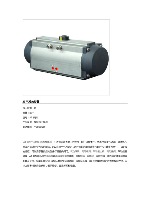
AT气动执行器加工定制:是品牌:耀一型号:AT系列产品用途:控制阀门驱动驱动能源:气动执行器AT系列气动执行器机构是我厂引进意大利先进工艺技术,自行研发生产。
并通过专业气动阀门测试中心对该产品进行全方位的测试。
它以压缩空气为动力,通过齿轮活塞传动将气缸内气压转换为0°——180度的扭矩。
可作用于各类旋转型角行程各类阀门、气动球阀、气动蝶阀、气动截止阀、气动闸阀、气动旋塞阀等。
AT系列精小型气动执行器机构设计简单紧凑,风格独特,全密封,内部气路,经济和无须连接管线外露而受损。
采用ISO5211连接标准为安装电磁阀、信号回讯器、阀门定位器或其它附件都极其方便。
设计上都考虑到安全操作,便于维修,容易拆卸和组装。
AT气动执行器外壳是由铝合金挤压拉制成型,表面喷砂并经硬质阳极化氧化处理,能够防腐、耐磨。
具有重量轻,外型美观强度和密封可靠。
醇缩醛轴垫片的活塞导向环肯有很低的磨擦阻力,能够吸收活塞侧向推力。
气缸内壁经过珩磨,以减小整体运动磨擦力,在输出轴的顶部的底部装有醇缩醛轴承,以降低旋转磨擦阻力,延长使用寿命。
端盖、活塞是铝合金压铸精制成型,具有良好的抗断裂性能。
端盖表面外涂高强度环氧树脂漆,一般能耐弱酸、弱碱及清洗剂。
输出轴采用45#碳钢制成,表面电镀处理。
开度指示器能真观地显示出“开”或“关”的位置,容易拆除以便于扳手操作。
行程调节螺丝可机械限制气动气动执行机构的转动角度,它以现场方式调整气动执行机构开或关的位置。
可使标准产品在0°和90°两位置有±5°的可调范围。
确保与阀门的同步精度。
所有气动执行机构在出厂前,轴承和导向环都经过润滑油脂润滑。
在正常操作环境下,必须通过空气油雾器进行润滑。
所有密封(包括活塞密封)均可选用丁晴橡胶(标准型-20℃~+80℃)、硅橡胶(低温型-40℃~+80℃)、氟橡胶(高温型-20℃~+150℃)。
AT气动执行器工作原理:当压缩空气从A孔进入两活塞之间的中腔时,由于压力作用使两活塞分离。
气动执行器的产品说明书

S E R I E S P L S O L E N O I D V A L V E SDirect acting solenoid valves Series PL2/2-way - Normally Open (NO)3/2-way - Normally Closed (NC) and Normally Open (NO) 3/2-way - Universal (UNI)Series PL solenoid valves are available in the normally closed, normally open and universal versions. They can be mounted on single sub-bases or manifolds.Please note that all Series PL solenoid valves are supplied with direct current (DC). To operate in alternating current (AC), it is necessary to use the connector with bridge rectifier Mod. 125-900.»Application sectors: - Industrial Automation - Life Science - Transportation »Mounting on a single base (M5 connections) or on manifold (M5 or fittings Ø3 and Ø4)GENERAL DATATECHNICAL FEATURES Function OperationPneumatic connections Orifice diameterFlow coefficient kv (l/min) Operating pressure Operating temperature MediaResponse time Manual override Installation2/2 NO - 3/2 NC - 3/2 NO - 3/2 UNI direct acting poppet type on subbase 0.8 ... 1.6 mm 0.30 ... 0.62 0 ÷ 3.5 ... 10 bar0 ÷ 50 °C (FKM) / -50 ÷ 50 °C (low temperature NBR on demand)filtered air class [5:4:4] according to ISO 8573-1:2010 (max oil viscosity 32 cSt), inert gas ON <10 ms - OFF <15 msmono/bistable - PBT 3/2 versions onlyin any positionMATERIALS IN CONTACT WITH THE MEDIUM Body SealsInternal parts brass - PBT - PPSFKM - NBR - EPDM (on demand) brass - stainless steelELECTRICAL FEATURES VoltageVoltage tolerance Power consumption Duty cycleElectrical connection Protection class6 ... 110 V DC - other voltages on demand ±10% 1.2 ... 3 W ED 100%industry standard connector (9.4 mm) IP65 with connectorSpecial versions available on demandS E R I E S P L S O L E N O I D V A L V ES* 3/2 NO IN-LINE version: the position of the ports 1 - 2 - 3 is identical to 3/2 NC versionCODING EXAMPLES E R I E S P L S O L E N O I D V A L V E SSeries PL solenoid valve - 2/2-way NO - series PD interfaceSupplied with: 2x O-Rings2x M3x20 screws for mounting on metal or2x Ø3x23 screws for mounting on plastic(opt. P)* add - VOLTAGE - FIXING(see CODING EXAMPLE)Series PL solenoid valve - 3/2-way NCSupplied with: 1x interface seal2x M3x20 screws for mounting on metal or2x Ø3x23 screws for mounting on plastic (opt. P)Also available ST models forT amb. -50 ÷ 50 °C with NBR seals.* add - VOLTAGE - FIXING(see CODING EXAMPLE)S E R I E S P L S O L E N O I D V A L V E S2x M3x20 screws for mounting on metal or2x Ø3x23 screws for mounting on plastic (opt. P)Also available ST models forT amb. -50 ÷ 50 °C with NBR seals.* add - VOLTAGE - FIXING(see CODING EXAMPLE)Series PL solenoid valve - 3/2-way NO IN-LINESupplied with: 1x interface seal2x M3x20 screws for mounting on metal or2x Ø3x23 screws for mounting on plastic (opt. P)Also available ST models forT amb. -50 ÷ 50 °C with NBR seals.* add - VOLTAGE - FIXING(see CODING EXAMPLE)S E R I E S P L S O L E N O I D V A L V E S2x M3x20 screws for mounting on metal or2x Ø3x23 screws for mounting on plastic (opt. P)Also available models for T amb. -50 ÷ 50 °C with NBR sealsVacuum operation with max. pressurereduction* add - VOLTAGE - FIXING(see CODING EXAMPLE)S E R I E S P L S O L E N O I D V A L V ESSingle sub-base for 15mm size 2 way interfaceSingle sub-base suitable for 2-way solenoid valves Series PD and PL models PD000-2A..., PL000-9B... Use solenoid valves with fixing screws for metal (see codification page)Material: anodized aluminiumConnections: G1/8 threadsSingle sub-base for 3-way solenoid valve size 15 mmSingle sub-base suitable for Series P - PL - PN - W 3-way solenoid valveUse solenoid valves with screws for mounting on metal (see coding)Material: anodized aluminiumConnections: M5 threadsSingle manifold with rear outletsManifold suitable for Series P - PL - PN - W 3-way solenoid valveUse solenoid valves with screws for mounting on metal (see coding)Material: anodized aluminiumS E R I E S P L S O L E N O I D V A LV E SManifold - single side valve - frontal outletsManifold suitable for Series P - PL - PN - W 3-way solenoid valveUse solenoid valves with screws for mounting on metal (see coding)Can be fixed through DIN 46277/3 guide with the accessory PCF-E520.Material: anodized aluminiumManifold - double side valve - bottom outletsManifold suitable for Series P - PL - PN - W 3-way solenoid valveUse solenoid valves with screws for mounting on metal (see coding)Material: anodized aluminiumManifold - double side valve - frontal outletsManifold suitable for Series P - PL - PN - W 3-way solenoid valveUse solenoid valves with screws for mounting on metal (see coding)Can be fixed through DIN 46277/3 guide with the accessory PCF-E520.Material: anodized aluminiumS E R I E S P L S O L E N O I D V A L V ESPosition valve capSupplied with:1x position valve cap 1x interface seal2x screwsConnector Mod. 125-... - industrial std. 9.4 mmConnector Mod. 125-... - industrial std. 9.4 mm - 90° cableThe internal rectifier circuit of the connectorMod. 125-900 allows to use solenoid valves with different AC voltage, even if the voltage indicated onthe solenoid valve is DC.S E R I E S P L S O L E N O I D V A L V E SConnector Mod. 125-... - industrial std. 9.4 mm - in-line cablewithout electronicsConn. Mod. 125-... - ind. std. 9.4 mm - in-line cable+rectifierwith voltage rectifierAC/DC。
AT Controls 手动和自动旋转阀门文档说明书
9955 International Blvd. • Cincinnati, Ohio 45246 Phone: 513.247.5465 Fax: 513.247.5462Engineer: AMZ No.: DI00043Date Created: 07/09/2019 Date Modified: TSM ExtensionsTSM’s are designed for use with fugitive emissions to act as another form of packing on valve series that are already designed for fugitive emissions. When used manually the handles are lockable. TSM’s also allow for an extended mounting pad to which an actuator can be directly mounted. They can be added to the 22, 24, 33, 55, 77, T77, H78, 8R, 88, 90, D9 and F91 Series. See dimensional drawings P02774, P02776, T11580, and P02997 below.Spring Return HandlesSpring return handles are designed for manual operation and can spring open or close. Depending on the set up the valve will either spring open or closed when the handle is released. They are made up of a triangle pad and a handle. The spring is contained in the handle and is attached to the triangle pad, which can be seen in P03000 along with dimensions and applicable sizes. They can be added to the 22, 33, 77, 88/F88, F91, D9, FD9, 8R, F8R, 83/F83, and 90/F90 series. The F91, 8R / F8R, 83/F83 and 90/F90 series will additionally require a TSM for mounting purposes.Manual Valve with Limit SwitchLimit switches can be mounted to a manual valve using a coupler and a “C” shaped bracket.MATERIALDATECHECKED BY DESCRIPTION9955 INTERNATIONAL BLVD.CINCINNATI, OHIO 45246PHONE: (513) 247-5465FAX: (513) 247-5462DRAWN BY DATEAMZSpring Return Handle Dimensional Drawing07/09/19DO NOT SCALE DRAWINGRELEASED BY CMB07/09/19DATECMB07/09/19VALVES, ACTUATORS, AND AUTOMATION CONTROLS。
气动执行器手动操作说明书

Publication number F171EDate of issue 9/99Jackscrews provide a simple method of manually operating a pneumatically actuated valve. Power air supply may be unavailable during commissioning or emergency circumstances. The jackscrew may then be used to drive the piston of the pneumatic actuator reproducing the effect of the power air supply.1.0 Operating Instructions1.1Ensure power medium (air, gas, etc.) to actuator is notactive. Try to operate directional control valve locally. Ifpower medium is active at actuator, but below ratedpressure, ISOLATE the power medium from the actuator.1.2 Determine which way you wish to turn the valve shaft(most valves turn clockwise to close, but not all).1.3 Looking down on the actuator with the stop bolts awayfrom you (see document drawing #1256), operate the left-hand side jackscrew to turn the valve stem anti-clockwiseand operate the right-hand side jackscrew to turnclockwise.1.3.1On double acting actuators, ensure bothjackscrews are at full outboard position beforemanual operation of the valve.1.3.2On spring return actuators, only one jackscrewis provided as the spring operates the valve inthe other direction.1.4 Back off jamb nut at base of jackscrew.1.5 Ensure jackscrew is well lubricated with keystone GeneralPurpose 81L Grease or similar.1.6 Using wrench or handwheel, turn jackscrew clockwise topush actuator output through 90º. Do not exceed 90ºtravel; this may result in valve damage. Jackscrew torqueshould not exceed 800 inch/pounds. (90Nm).2.0 To Restore Actuator to Automatic Mode2.1Unscrew jackscrew to full outboard position.2.2Retighten jamb nut on cylinder side. Screw conical sealwasher against cylinder end flange before tightening jambnut. Tighten jamb nut to approximately 1,000 inch/pounds.(113Nm).3.0 Maintenance3.1Ensure stainless steel jackscrew threads are always wellgreased. This will make operation considerably easier. 4.0 Retrofitting JackscrewSee Document Drawing #1349.4.1Before attempting retrofit, ensure power medium isisolated from actuator and locked off.4.2Ensure no residual pressure is present in the actuatorcylinder.4.3Cylinder side jackscrew4.3.1 Disconnect air supply to cylinder end flange.4.3.2Remove four tie rod nuts 58.4.3.3Remove cylinder end flange 54 and seal 60.Technical information for‘P’ Range valve actuatorsTIS 40Operating and maintenanceInstructions - Jackscrews4.3.4Remove piston rod bolt 63.4.3.5Fit piston rod bolt 70 supplied with jackscrewretrofit module and tighten to recommendedtorque.4.3.6Coat hex nylon piece 71 with type 620 Loctitethen assemble into piston bolt 70.4.3.7Unscrew jackscrew to full outboard position.4.3.8Fit end flange with jackscrew and new sealprovided with retrofit module over the tie rods57.4.3.9Replace tie rod nuts 58 and tighten torecommended torque.4.3.10Retighten jamb nut 77 (as 2.2).4.4Rod cover side jackscrew4.4.1Remove piston rod cover bolts 202.4.4.2Remove piston rod cover 201.4.4.3 Fit piston rod bolt 210 supplied with jackscrew.Retrofit module and tighten to recommendedtorque4.4.4Coat hex nylon piece 211 with type 620 Loctitethen assemble into piston bolt 210.4.4.5Unscrew jackscrew to fully outboard position onjackscrew piston of cover.4.4.6Fit jackscrew piston rod cover over piston rod.Ensure flange gasket 51 and rod seal 50 are inplace.4.4.7Replace piston rod cover bolts 202 andlockwashers 203 and tighten to recommendedtorque.4.4.8Tighten jackscrew jamb nut.5.0Recommended Torques (lbs. ft.)Piston Bolt (Item 70)2505/8 UNC Grade 8210325 1 UNC Grade 88665001-1/4 UNC Grade 81750Piston Rod Bolt (Item 210)2505/8 UNC Grade 5150325 1 UNC Grade 55835001-1/4 UNC Grade 51097Tie Rod Nut (Item 58)250 05-085/8 UNC95250 10-123/4 UNC169325 10-143/4 UNC169500 123/4 UNC169Jackscrew Cover Bolt (Item 202)2501/2 UNC Grade 5753255/8 UNC Grade 5150500 1 UNC Grade 5525。
【精品资料】气动阀门_气动执行器_说明书
气动执行器详细说明:气动执行器DP系列特征结构形式:双活塞齿轮齿条式结构输出扭矩平稳单作用加弹簧,单双作用同一缸体.型号有DP32/DP45/DP52/DP63/DP75DP75/DP83DP92/DP110/DP127/DP143/DP160/DP190/DP210/DP 240/DP270/DP300/DP350/DP400/DP500/DP600.AP50/AP100/AP150/AP200/AP250/AP300/AP350/AP400/AP450/AP500/AP600/AP700/AP800JAT50D/SJAT63D/SJAT75D/SJAT90D/SJAT100D/SJAT115D/SJAT125D/SJAT145D/SJAT160D/SJAT190D/SJAT210D/SJAT240D/SJAT270D/SJAT50D/SJAT63D/SJAT75D/SJAT90D/SJAT100D/SJAT115D/SJAT125D/SJAT145D/SJAT160D/SJAT190D/SJAT210D/SJAT240D/SJAT270D/SISO5211F03F04F05/F07F05/F07F05/F07F07/F10F07/F10F10-F12F10/F12F12F12F14F14防爆电动执行机构防爆电动执行器角行程防爆电动执行器JDA-60电动执行器JDA-20电动执行器JDA-10电动执行器JD-05电动执行器JDA-05JDA-10JDA-20.40JDA-60JDA-100JDA-20060Kgfm1A/100V0.45A/200V30秒/50HZ氧气阀门的工作原理气动V型调节球阀气动套筒调节阀气动薄膜直通双座调节阀气动薄膜直通单座调节阀气动薄膜双座调节阀HSC笼式调节阀气动截止阀对夹式气动浆液阀气动插板阀气动带手动楔式闸阀气动法兰闸阀Q644/Q645F气动法兰三通球阀Q611V气动塑料球阀Q641F4气动衬氟球阀Q611气动二片式球阀气动卸灰球阀气动固定式球阀ZSHO-16型气动O型切断球阀气动V型调节球阀Q647F大口径系列固定式气动球阀Q671气动对夹球阀Q641F气动法兰球阀Q644/45F气动球阀(三通)Q672F气动球阀(薄型)Q611F气动球阀(片式)D671V气动蝶阀(塑料)D671X7气动氟橡胶对夹蝶阀D673H气动三偏心对夹蝶阀D671X气动粉尘蝶阀气动通风蝶阀气动蝶阀(法兰软密封)GT气动蝶阀(美标衬氟)D681气动卫生卡箍式蝶阀GZK气动高真空蝶阀D641X气动法兰橡胶密封蝶阀D671X气动蝶阀D643H法兰式气动硬密封蝶阀JDAT系列气动执行器AW/AW-S气动执行器气动执行器电动三通合流调节阀VB7000电动调节阀电动角形高压调节阀电动智能调节阀电动套筒调节阀电动笼式单座调节阀电动双座调节阀电动单座调节阀电动焊接截止阀电动截止阀电动刀型闸阀电动弹性座封闸阀高温高压电站闸阀电动闸阀电动V型球阀电动塑料球阀电动片式球阀电动内螺纹三通球阀电动法兰球阀电动对夹球阀电动法兰固定球阀电动球阀(衬氟)电动三通法兰球阀电动真空蝶阀电动多层次硬密封蝶阀电动三偏心对夹蝶阀电动四氟密封对夹蝶阀电动衬氟蝶阀电动粉尘专用蝶阀电动塑料蝶阀电动通风蝶阀电动法兰软密封蝶阀电动快装蝶阀防爆电动执行机构防爆电动执行器角行程防爆电动执行器JDA-60电动执行器JDA-20电动执行器JDA-10电动执行器JD-05电动执行器GB JB SH HG ANSI API JIS BS DIN GB13927JB/T9092API598标准内螺纹式气动角座阀BDJ-01F气动阀门回信器闸阀齿轮传动气动闸阀气动闸阀手动控制气动闸阀气动闸阀气动闸阀气动球阀气动排渣阀气动截止阀气动蝶阀气动蝶阀气动刀形闸阀气动带手动闸阀气动阀门定位器对夹式软密气动蝶阀气动阀门定位器超薄型气动球阀Q647固定气动球阀Q641气动球阀637H对夹式硬密封气动蝶阀(一片二片三片)气动阀门气动阀门回信器ITS-100限位开关APL-310N限位开关BAPL-510N回信器ITS-102VCX-5000限位开关德国EBRO限位开关ALS-10信号开关盒德国MSK NSK限位开关阀门回信器MPL-510N 型阀门回信器MPL-210N行程开关阀门TOPWOR限位开关限位开关ITS-300APL-210N TOPWOR限位开关韩国ITS-102BAPL-310N BAPL210N BAPL-410N进口限位开关进口回信器MPL-210N油枪油阀位置开关CHX210TOP-312N TOP312N APL-312机械二位式位置开关MASTS限位开关atsb-v3-2限位开关盒意大利SOLDO回信器油枪行程开关KINETROL限位开定位器ROTECH SIRCA回讯器气动阀门回信器CAKNA限位开关HAPL-21ON APL-210N ITS-111MASTS限位开关J+J限位开关EBRO MSK限位开关ULS-210ALS10HIC-210N限位开关NTS-C12限位开关NTS-A10限位开关YT-850限位开关WGT气动执行器WGT专业生产厂家3EGTD52气动执行器新一代意大利型气动执行器WAT专业生产厂家电动执行器专业生产厂家WX-10WX-20WX003GT气动执行器意大利型AT气动执行器电动执行器电动执行器厂家电动执行器价格优惠电动执行器质量保证BLD05-BLD200 DAT气动执行器气动双活塞执行器型号OBD双作用式型号OBD-S单作用式弹簧返回JM电动(调节式)阀门执行器可选用AC110V220V380V DC12V24V电源输入信号4-20MA0-10V或1-5V。