美国ResQmax气动抛投器使用说明书
气动式救生抛投器

气动抛投器参数:1、外形尺寸:1000×170×260 mm2、净重:7Kg 使用方法:水平发射时抛投主体角度在(30-35度)垂直发射时抛投主体角度在(45-50度)。
发射采取抛物线式,严禁直接对被救目标。
以免伤害被救者和避免发射气瓶的损毁)注意事项:1、严禁将救援发射器直接对人体发射,以防造成人员的伤害。
2、在对发射气瓶充气时,不准对向人处,停止使用发射器应将放气螺塞打开,排空发射瓶内全部气体,使压力表回到“0”。
3、发射体上的安全阀是发射器的重要零件,通常时不允许去调整它。
4、此装备由专人操作,严禁用于救援以外的作业。
5、陆上使用时,注意发射气瓶的保护,随时保持喷咀的清洁,若气瓶受碰撞有损伤或变形应及时更换。
执行标准:GB/T 27906-2011图片:检测认证:厂家检测简介:PS气动抛投器,是以高压气体为动力,主要由发射体、发射气瓶、自动充气装置、救生圈、锚钩、绳索等部分组成,可将绳索或自动充气救生圈或锚钩快速、安全、准确的发射至目标。
应用于消防救援、特警救援、急流救援、水上救援、船只之间、船岸之间的绳索连接与抛投救生圈、锚钩作业。
结构:PS-1气动抛投器可抛投锚钩(配φ6mm的救援绳)及救生圈(配φ4mm的救援绳);PS-2救生抛投器可抛投救生圈(配φ4mm的救援绳)及绳索(配φ2mm的救援绳);PS-3射绳枪可抛投绳索(配φ2mm的救援绳);功能:应用于消防、特警、水上、冰上等场所的救援活动。
气动抛投器以高压气体为动力,主要由发射体、发射气瓶、自动充气装置、救生圈、锚钩、绳索等部分组成,可将绳索或自动充气救生圈或锚钩快速、安全、准确的发射至目标。
应用于消防救援、特警救援、急流救援、冰上救援、船只之间、船岸之间的绳索连接与抛投救生圈、锚钩作业。
PS-1配置:抛投器主体一支、气瓶一个、自动充气救生圈一件、救生圈保护套三个、气瓶保护套两件、救生圈充气瓶两个、水敏感元件两个、锚钩一件、高压气管一件、绳桶(内装6mm 4mm绳子)两个主要参数:抛投距离:4mm绳带救生圈水平发射距离70-90m6mm绳带锚钩水平发射距离50-70m垂直距离25-30m使用拉力:6mm绳为160kg 4mm绳为100kg极限拉力:6mm绳为800kg 4mm绳为300kg外形尺寸:940*165*400重量:8.0kg。
亚希 美国,弧度79P气动系统操纵器安装、使用和维护手册说明书

PneumaticSeries 79P ActuatorInstallation, Operation and Maintenance ManualUSER INFORMATIONTable of ContentsDescription (3)Air Requirement (3)Installation (4)Type 21 Ball Valves (4)Type 23 Ball Valve (3-way) (4)Type 56/57 Butterfly Valves (4)Type 75 Butterfly Valves (5)Operation (6)Single Acting: (6)Double Acting: (6)Optional Solenoid Valve (See drawing #004PNU) (6)Maintenance (7)CAUTION --- DANGER (7)Dis-assembly of Actuator (7)Assembly of Actuator (7)Repair Kits (8)Engineering Data (9)Actuators (9)Solenoids (9)Exploded Views (10)Typical PA-Series (10)Typical P-Series (11)Typical Series P79P (PAG) (12)Typical Series S79P (316SS) (13)Series 79P Pneumatic Actuator IntroductionDescriptionThe Series 79P Pneumatic Actuator is a quarter turn operator, that has two opposed pistons with racks engaging with a single pinion on the actuator shaft. Racks and pinion engage with massive teeth over full length of pinion, resulting in balanced forces with minimal backlash.Pistons and racks are molded polyarilamide for the PAG version, and Aluminum Alloy for the 316SS and Cataphoresis/Rilsan version. Piston guides are Polyacetal for sizes A through D5, and PTFE Bronze for sizes E through M. Pinion gears are Aluminum Alloy. Body and end caps are 316SS, Polyamide glass filled, or cast Aluminum Alloy Cataphoresis and Rilsan coated inside and outside. Actuator shaft is Stainless Steel or Cataphoresis coated steel. O-Rings are self-Lubricating BUNA-N. Air connections are ¼” FNPT.Actuator shaft can be used for manual override. Remove position indicator, and insert wrench on to shaft square and rotate. A de-clutchable gear override is required for air to air valve sizes 8” and above, and all air to sprig models.Air RequirementThe condition and quality of the compressed air supply to an actuator will affect the efficiency and the life of the seals, guides, and actuator in general. We recommend installing a shutoff valve ahead of actuator to allow shutoff of air to allow removal of valve and actuator for maintenence.80psi, clean, instrument quality dry air or gas is recommended for satisfactory operation. Lubricated air is acceptable, but is not necessary as the o-ring material is self-lubricating BUNA-N.If air lubricators are used, the lubricant selected must be compatible with actuator internals!Actuator may be used with liquid as the power source as long as liquid is compatible with actuator internals, and contains no suspended particles. The actuator environment temperature limits are -25︒F and 195︒F.InstallationType 21 Ball ValvesPosition the valve and the actuator to corresponding positions (either OPEN or CLOSED). The flats on the actuator shaft extension and the indicator knob should indicate valve positionType 21 Ball Valves (See Drawing #0114BV sizes ½” –2”)Install mounting bracket #3 to actuator #2 using bolts #8 and washers #9. Insert coupling #4 on stem of valve #1 and then bolt valve #1 to mounting bracket #3 using bolts #5, nuts #6, and washers #7.Note: All bolts should be snug and not excessively over tightened. Type 21 Ball Valves (See Drawing #0115BV sizes 2-1/2” - 4")Install mounting bracket #3 to actuator #2 using bolts #8 and washers #9. Insert coupling #4 on stem of valve #1 and then bolt valve #1 to mounting bracket #3 using bolts #5, nuts #6, and washers #7.Note: All bolts should be snug and not excessively over tightened.Type 23 Ball Valve (3-way)Position the valve and the actuator to corresponding positions (either OPEN or CLOSED). The flats on the actuator shaft extension and the indicator knob should indicate valve positionType 23 Ball Valves (3-way): (See Drawing #0139BV, sizes ½” - 4”) Install mounting bracket #3 to actuator #2 using bolts #8 and washers#9. Insert coupling #4 on stem of valve #1 and then bolt valve #1 to mounting bracket #3 using bolts #5, nuts #6, and washers #7.Type 56/57 Butterfly ValvesPosition the valve and the actuator to corresponding positions (either OPEN or CLOSED). The flats on the actuator shaft extension and the indicator knob should indicate valve positionCAUTION: If valve is in line, system must be shut down and have no line pressure before removing throttle plate and retaining washer.Butterfly Valves (See Drawing # 0204BF sizes 1-1/2” - 6”)No specially machined stem or valve body drilling required. Remove handle (remove handle cap and hex head bolt) to expose throttle plate screws. Remove throttle plate and retaining washer to expose existing bolt pattern. Insert actuator shaft adapter #9 into actuator.Mount bracket #2 to actuator with bolts #7 and tighten evenly. Install valve #1 onto mounting bracket and align stem of valve to engage with actuator shaft adapter. (Line scribed on top of stem indicates disc orientation). Install bolts and nuts #3 thru #6 and tighten evenly. Flats on actuator shaft indicate valve position. (Disc Orientation)Butterfly Valves (See Drawing #0167BF sizes 8” - 16”)No specially machined stem or valve body drilling required. Remove gear operator by removing 4 thru bolts in body of valve to gear operator and lift off. Insert actuator shaft adapter #9 into actuator. Mount bracket #2 to actuator #10 using bolts #7 and washers #8. Install valve #1 to mounting bracket #2 using bolts #3, nuts #6, and washers #4, keeping in mind line scribed in valve stem indicates disc orientation before mounting and by flats on actuator shaft after mounting.Type 75 Butterfly ValvesButterfly Valves (See Drawing #1230 sizes 18” - 24”)No specially machined stem or valve body drilling required. Remove gear operator by removing 4 thru bolts in body of valve to gear operator and lift off. Insert actuator shaft adapter #9 into actuator. Mount bracket #2 to actuator #10 using bolts #7 and washers #8. Install valve #1 to mounting bracket #2 using bolts #3, nuts #6, and washers #4, keeping in mind line scribed in valve stem indicates disc orientation before mounting and by flats on actuator shaft after mounting.CAUTION:If mounted unit is installed other than straight up, the actuator should be supported individually in order to prevent side loading and loosening up of fasteners.OperationSingle and Double Acting:Pressurized air is introduced via the bottom, or right, port and displaces two opposed pistons. When the pistons are displaced, they in turn rotate the actuator output shaft counterclockwise, which opens the valve. This action is the same for single acting and double acting actuators.Single Acting:When the pressurized air is removed from the bottom, or right, port, the compressed springs located at the opposite side of the pistons extend. As the spring extend, they in turn rotate the actuator output shaft in a clockwise rotation, which closes the valve. The springs are ALWAYS under tension, so caution must be exercised.Double Acting:When the pressurized air is removed from the bottom, or right, port, the unit remains in the same position until pressurized air is applied to the top, or left, port (unlike the single acting actuator). When the pressurized air is introduced to the top port, it is channeled to the opposite side of the pistons, driving them to their original position, which in turn rotates the actuator output shaft in a clockwise direction, closing the valve.Optional Solenoid Valve (See drawing #004PNU)An optional solenoid valve (ASCO 8401 NAMUR mount) can be supplied mounted directly to the actuator. The cycling is accomplished by energizing the solenoid coil for one valve position (typically open), and de-energizing for the opposite valve position (typically closed). The unit is electrically fail safe; so it will return to its de-energized position on electrical failure, provided the air supply is not interrupted.The 8401 solenoid is equipped with mufflers, speed controls, a manual override, and 18 inch long #18 AWG lead wire.The speed controls are needle valves that will reduce the C V value or increase the cycle time by creating back pressure within the actuator. Speed control adjustments are independent for the opening and closing strokes.Caution: If speed control adjustments are screwed in too far, actuator can not exhaust properly and will not cycle!!The manual override is engaged by pressing and rotating the red slotted screw clockwise 90 for the open position. Once the valve is open, simply rotate the red screw counter-clockwise 90 for the closed position. Caution: Manual override will not work without air supply!!MaintenanceThe Series 79P double rack and pinion actuators do not need any preventative maintenance.Periodic checks should be performed to ensure proper tightness of all fasteners.Caution: Isolate actuator from electrical power supply and compressed air supply before any maintenance is performed. Make sure both sides of pistons have been bled off.Dis-assembly of Actuator1. Remove end cap by slowly loosening end cap screws, in a crossing pattern2. Remove springs3. Repeat steps 1 and 2 for opposite end cap4. Rotate shaft counter-clockwise to remove pistons.5. Remove snap ring from shaft.6.Slide shaft through actuator body and out the bottom.Assembly of Actuator1. Install shaft, washer, and secure with snap ring; making sure that the snap ring is seated2. With the air inlet ports facing you, install pistons into actuator body with the rack of the right piston facing the air inlet ports.3.Rotate shaft CCW (beyond open position) to engage both racks. Next, rotate shaft CW to pull pistons to the closed fully position (actuator shaft should not be cocked, and there should be equal distance between the actuator body and the pistons).4. Install desired number of springs and end cap to actuator body.5. Set end cap into position, and tighten screws, in a crossing pattern6.Repeat steps 5 & 6 for other end.CAUTION --- DANGER Failure to use proper tools can result in SERIOUS INJURY! The actuator springs are very strong and are compressed whenactuator is assembled.Repair KitsNOTE: When ordering replacement actuator parts and/or options specifymodel #, serial number (and voltage, if applicable).Each repair kit includes the following (Please reference exploded views)Engineering DataActuatorsSolenoidsAll solenoid coils may be used at +10% to -10% of rated voltages. Coils are 50/60 Hertz and are rated for continuous duty if operated at 60 Hertz.Note: Consult factory for non-standard voltages and for continuous duty at 50 Hertz.Rated Voltage In Rush Current Milliamp @ 60 Hz Holding Current Milliamp @ 60 Hz Watts @ RatedVoltages120 VAC 113 71 6.2 24 VAC 566 360 6.2 240 VAC 56 35 6.2 12 VDC---583724 VDC --- 292 7Solenoids are furnished with 18 inch long #18 AWG lead wire.Typical P-Series。
抛投器使用方法

抛投器使用方法
抛投器是一种用来投掷物体的器具,常见于军事、狩猎、娱乐等领域。
以下是一般抛投器的基本使用方法:
1.准备工作:
o确保工作区域的安全性,避免人员和物体进入射程范围内。
o根据抛投器的类型,选择合适的投掷物体,如石块、球状物或箭等。
o检查抛投器的结构和材质是否完好,确保无损坏或松动的部分。
2.装填投掷物:
o根据抛投器的设计,将投掷物体置于抛投器的投掷槽或装填杆上。
o注意保持投掷物体的平衡和稳固,确保投掷物体不会偏斜或滑落。
3.调整和瞄准:
o调整抛投器的张力或增加弹性力,以增加投掷物体的速度和飞行距离。
具体的调整方法可能因抛投器
类型的不同而异。
o使用瞄准器或凭借经验,调整抛投器的方向和角度,以对准目标。
4.投掷:
o使用手柄或其他操作装置,将投掷物体从抛投器释放出来。
o避免在释放过程中产生突然的动作,保持稳定性,以确保投掷物体的准确度和稳定性。
5.安全注意事项:
o在使用抛投器时,始终遵循安全操作规则,确保不会对自己和他人造成伤害。
o确保在合法的场所使用抛投器,并遵守当地法律和规定。
o在使用抛投器时,避免对人、动物或财产造成损害。
请注意,具体的抛投器使用方法可能因抛投器类型和设计的不同而有所区别。
在操作之前,请仔细阅读和遵守抛投器的使用说明书,并严格遵守制造商的建议和警告。
确保在安全环境中使用抛投器,并通过适当的训练和实践,熟悉和掌握正确的使用技巧。
美国RSI公司ResQmax远程抛射救生枪

美国RSI公司ResQmax远程抛射救生枪作者:王安民,等来源:《轻兵器》 2011年第6期美国RSI(Rescue Solutions International)是一家专业从事救援产品研发和销售的公司,ResQmax公司则是其旗下的子公司。
ResQmax远程抛射救生枪是ResQmax公司的主打产品。
该枪采用压缩空气为动力,最远发射距离可达122m,应用于消防救援、水上/冰上救援、船只/船岸之间的绳索连接等。
该枪定位于民用装备,其结构和功能设置与舰艇上装备的采用空包弹发射的军用救生枪有很大不同。
发射部件组成1 根据救援需要,弹体前方既可以安装攀爬用的锚钩(上图);也可以安装内装救生圈的壳体(下图)。
使用时,将装有救生圈的壳体或锚钩装在弹体上,打开保险,对准目标区域发射即可。
该枪采用折叠式枪托2 全枪各部件分解状态3 弹体尾部特写。
弹体实际上是一个压缩空气瓶,尾部设有喷嘴、充气阀以及与锚钩、救生圈等相连接的绳索4 枪身气室口部特写。
弹体上的充气阀打开后,弹体开始向枪身气室内充气,可通过枪身尾部的压力表查看气室内的压力。
达到需要的气压后,关闭充气阀即可5 枪身尾部的压力表特写6 枪身右侧设有保险和充气阀手柄。
向内按压保险才可发射。
当按下保险后未发射,须将保险顺时针旋转,保险可被弹起,回到保险状态。
图中即为保险状态。
将充气阀手柄顺时针旋转90°,即可带动弹体尾部充气阀旋转为气室充气,充好气后需要将其复位,以免发生危险。
图为充气状态7 枪身左侧设有气室泄气阀。
气室充好气后,如果未使用,必须将气室内的气体排出,以防止发生危险。
用扳手将泄气阀旋柄扳至最下方即可排出气室内的气体8 枪托折叠状态。
枪托底部的挂钩可与枪管上方的挂钩扣合在一起,方便携行与置放9 绳筒内装绳索,绳索的一端与弹体前方的锚钩或救生圈相连,另一端固定在枪身下方。
当发射锚钩时,锚钩可将被救船只钩住,以进行救援;发射的锚钩也可用于攀爬。
救生抛投器(美式+韩式)救生抛投器

使用须知 !!!
1、根据环境、条3、避免接触油、酸等化学物。
4.救生圈应存放在温度为0- 350C,相对湿度不大于85%的室内, 且 不受挤压。 5.救生圈有效期为三年,每年对气瓶的质量进行一次检测。 6、救生圈经过使用后,必须由专业技术人员进行气密性检查,并更
救生抛投器特点:
是专业救援用的便捷式救生抛投器,抛射距离可达75M以上,可
作为船对船、船对岸、高楼和山涧的抛绳救援使用。该产品重量 轻,携带方便,枪式发射便捷简单,抛射目标的准确性高;可根据 不同救援目的抛射不同救援弹。 救生抛投器适用范围: 1、水上救生:适用河边、湖边、江边和海边等复杂救援场所,快 速实现短距离水上救生。 2、陆用救援:适用民用、警用、军用、消防、船对船、船对岸、 高楼或山涧等救援场合的抛绳作业。
换新的气瓶与自动充气装置及外壳。
谢谢观看
救生抛投器(美式+韩式)救生抛投器
救生抛投器: 韩式
工作压力:3000PSI/207bar、
抛射距离60-90米。
基本配置:发射枪、气瓶、 绳索、充气管、救生圈
抛投距离- 卢彤玖132-301-35357 264-39-13-268
救生抛投器 : 美式
1. 水陆两用,用于远距离抛投救生绳、救 生圈。 2. 气瓶气动喷射,由发射机械装置、发 射气瓶总成、充气装置、保护装置、快速 自动充气救生装置附件等组成。 3. 抛射范围60-120米。陆用时:绳长 150m、3mm直径陆用绳1条,水平发射距离 100m。水用时:长92m、6mm直径水用绳1条, 水平发射距离60m(带救生圈),自动充气 救生圈掉入水中自动充气浮起。
新一代气动救生抛绳器ResQmax
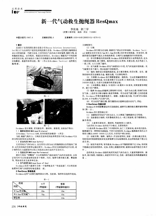
() 创 新地 采用 高压气 体 为动力 , 1 大大 增强 了抛绳 器 的安全 性 能。 () 发射 器设 计独特 , 2 可折 叠枪托 符合人一 机 工程原理 , 便于 瞄准射击 , 操作 简便 。
图一 2
R m x设 计新 颖, 用新 技术 、新材 料 、新 原 理, 有如 下特 点 : eQ a s 采 具 1 1抛 射距 离远 (A i u i t n e M X m m D a c ) s 以 R s m x T c i a 为例, eO a a t c l 具体 的射程 参数表 1 所示 : 当然, 根据 气瓶 压力 、引绳 的重量和 使用射 弹类型 的不 同, e Q a R s m x可 以 将 引 绳发 射 到更 远 的距 离 。 1 安全性 高 (A iu a e y 2 M )m mSf t) ( 它采用 高压气 体 为动力 , 比采 用 火药 为动力 的抛绳 器安全 性提 高 了很 这 多, 这尤其 体现在 发射和运 输过 程中 。R sm x的安全系统 始终 是开启 的, eQ a 设 计 独特 的压力减 缓盘 可 以阻 i因温度 过高 引起 的不安全 应力 。 E 1 3性 能优异 (A u e f r a c ) . M X m m P r o m n e i 拥 有专 利 的 “ 喷嘴 阀 ”可 以将 锚弹 内气瓶 快速 充气加 压存 放起来 , 以保 证 使用 时 可 以快 速连 续发 射 多 个锚 弹 。同 时,锚弹 可携 带 救生 圈 、攀 登梯 等 , 助使 用者 完成 多 种任 务 。 帮
应 用 技 术
I ■
CaiedCOyV h na hl i iccnengew n e T oRe s
新一代气动救 生抛绳器 R s a eQm x
渣扔油吸引器产品说明书

Rev. A 921589-0805/09M-150S-EM & M-150S-EA Economy Fuel PumpDo not leave the system running without fluids. “Dry running” can damage the pump.Do not pump the tank completely dry, as contaminants from the bottom of the tank may enter the pump.These instructions will help you operate and maintain your pump. This owner’s manual covers the 12-volt Economy Model electric gear pumps with automatic and manual nozzles.An automatic bypass valve prevents pressure build up when the pump is on with the nozzle closed. To avoid damage, do not run the pump more than 10 minutes with the nozzle closed.The duty cycle of this pump is 30 minutes ON and 30 minutes OFF . Allow the pump to cool for 30 minutes.This pump is designed for use only with gasoline (up to 15% alcohol blends such as E15), diesel fuel (up to 20% biodiesel blends such as B20) and kerosene. Do not use this pump for dis-pensing any fluids other than those for which it was designed. T o do so may damage pump components and will void the warranty.This pump is designed to operate on a typical 12-volt DC automotive electrical system. The pump is designed to operate with 12-volts DC at the motor leads and the ratings are deter-mined at this voltage. Performance may vary due to length of power cord, battery condition or output from vehicle charging system that will affect system voltage.Observe all safety precautions concerning safe handling of petroleum fuels.To ensure safe operation, all fuel transfer systems must be properly grounded. Proper grounding means a continuous metal-to-metal contact from one component to the next, including tank, bung, pump, meter, filter, hose, and nozzle. Care should be taken to ensure proper grounding during initial installation and after any service or repair procedures. For your safety, please take a moment to review the warnings below.To prevent physical injury, observe precautions against fire or explosion when dispensing fuel. Do not operate the system in the presence of any source of ignition including running or hot engines, lighted cigarettes, or gas or electric heaters. Observe precautions against electrical shock when operating the system. Serious or fatal shock can result from operating electrical equipment in damp or wet locations.Inspect external pump wiring regularly to make sure it is cor-rectly attached to the battery. To avoid electrical shock, use extra care when connecting the pump to power.Avoid prolonged skin contact with petroleum fuels. Use protec-tive goggles, gloves and aprons in case of splashing or spills. Change saturated clothing and wash skin promptly with soap and water.Observe precautions against electrical shock when servicing the pump. Always disconnect power before repairing or servic-ing. Never apply electrical power to the system when any of the coverplates are removed.If using solvent to clean pump components or tank, observe the sol-vent manufacturer’s recommendations for safe use and disposal.This pump is designed to self-prime with dry gears. Expect suction lift as follows:Manual Nozzle: 5.5 ft. (1.7 m) with diesel6.7 ft. (2.1 m) with gasoline Automatic Nozzle: 4.8 ft. (1.5 m) with diesel5.8 ft. (1.8 m) with gasolineIf you require a greater initial prime height, coat the gears with fluid by removing the plug on the top of the pump and pour a small quantity of motor oil into the gear cavity. Replace the plug and try again. A foot valve with pressure relief may be needed to maintain prime.Make sure all threaded fuel connections are wrapped with three to four turns of thread tape or a pipe thread sealant approved for use with petroleum fuels.Install Hose and NozzleAfter sealing threads, tighten the hose into the pump outlet and the nozzle on the hose. The nozzle can be placed in the nozzle holder only when the pump is off.AlwAyS follow SAfeTy PreCAuTIoNS wHeN oPer-ATING THIS equIPmeNT. revIew THe SAfeTy INSTruC-TIoNS. Before each use, repair leaks around seals or connec-tions. Make sure hoses are in good condition and connections are tight. Make sure the work area is dry. mAke Sure THe PumP IS ProPerly GrouNDeD. Repair any corroded or damaged wiring before use. Ensure the tank contains enough fuel. Make sure the fuel is not contaminated with debris.To Dispense fuelTurn on the pump by removing the nozzle from the holder and pushing up the switch lever. Insert the nozzle into the receiving tank and squeeze the handle to start fuel flow. When done, release the nozzle handle, turn the pump off, and return the nozzle to its holder.This pump is designed to be self-priming. If fuel is not delivered within 15 to 20 seconds, turn the pump off and refer to priming information in the Troubleshooting Section.An automatic bypass valve prevents pressure build up when the pump is on with the nozzle closed. T o avoid pump damage, do not run the pump more than 10 minutes with the nozzle closed.motor ProtectorThe pump contains a motor protector that provides added protection against motor damage. It must be reset manually.Clean and bond the suction pipe top and bottom as necessary. Thread the suction pipe into the inlet fitting and tighten snugly. Trim the suction pipe as necessary to leave approximately 1/2 in. (1.2 cm) clearance from the bottom of the tank. Clean the tank interior of all dirt and debris. Insert the suction pipe into the tank opening. Tighten the pump into the tank opening until snug. Do not cross thread.Make sure the tank is vented. A vent cap rated at 3 psi or less is recommended.Install electrical ConnectionsA grounding connection is provided. It is identified as a green colored binding head screw in the electrical cavity. Connect these pumps only to a 12-volt DC power source. Do not attempt connection to a 24-volt DC, 115-volt AC or 230-volt AC power source.For installation in unclassified areas, the supplied power cord, fuse and strain relief grip may be used.NOTE: These components have not been evaluated as part ofthe UL Listed Equipment and are not intended for use in a Hazardous (Classified) Location.To install the power cord, remove the electrical coverplate. If necessary, trim the power cord to the desired length. Strip 3 to 4 inches (7.5 to 10 cm) of outer insulation from the power cord end. Then strip 1/2 in. (1.3 cm) of insulation from the power cord wires. Slide the strain relief grip onto the power cord so that the threaded end of the strain relief grip faces the stripped power cord wires. Insert the power cord through the 1/2 inch NPT connection on the back of the pump. Using wire nuts, connect black wire to black and red wire to red in the pump’s electrical cavity. Position the wires inside the electrical cavity and tighten the strain relief grip securely. Make sure surfaces are clean.Install the coverplate and tighten securely.If pump is to be installed in a Hazardous (Classified) location, it must be installed by a licensed electrician and conform to Na-If the motor protector trips, reset by turning the switch OFF . Let the pump cool then turn ON again. If the motor protector trips again, see the Troubleshooting Section of this manual.This pump is designed for minimum maintenance. Motor bear-ings are sealed and require no lubrication. Inspect the pump and components regularly for fuel leaks and make sure the hose and power cord are in good condition. Keep the pump exterior clean to help identify leaks.Do not use this pump for water, chemicals or herbicides. Dispensing any fluid other than those listed in this manual will damage the pump. Use of the pump with unauthorized fluids will void the warranty.To Clean or replace StrainerTurn the pump off and disconnect from power. Remove the strainer coverplate. Remove the inlet strainer and inspect for damage or clogs. Clean the strainer with a soft-bristled brush and solvent. If the strainer is very dirty, compressed air may be used. If damaged, replace the strainer.Place the strainer in the cavity. Clean the coverplate and O-ring. Coat the O-ring lightly with grease. Ensure the coverplate O-ring is properly seated and tighten the strainer coverplate.Carefully route the power cord to the battery, protecting the power cord from hot surfaces, sharp edges or anything that WARNINGAlwAyS DISCoNNeCT Power before rePAIrING or ServICING THe PumP. Never APPly Power To THe SySTem wHeN ANy CoverPlATe IS removeD.A. SwITCH fAIlS To oPerATe moTor1. motor protector activated. Turn off switch. Allow motorto cool, then turn on switch.2. fuse blown. Inspect fuse in fuse holder on power cord.If blown, replace.3. Switch or electrical connections faulty. Inspect fordamaged motor protector, defective wiring or switch, or improper electrical connections. Replace as necessary. 4. motor burned out. Inspect and replace as necessary.b. moTor ruNS buT DoeS NoT PumP fluID1. Suction pipe clogged, damaged, or missing. Removepump from tank. Inspect suction pipe. Clean or replace, as necessary.2. Gear coverplate or o-ring damaged. Remove andinspect the coverplate and O-ring. Replace as necessary. 3. Strainer clogged or defective. Inspect and clean asrequired.4. bypass poppet o-ring worn, missing or dirty. Inspectthe O-ring. Replace as necessary.5. System air leak. Tighten all pump fittings and connec-tions. Inspect suction pipe for leaks or damage.6. Poor connections or low voltage. Make sure electricalconnections are secure. Also check battery voltage. 7. fuel level low. Fill tank.8. motor running backwards due to incorrect polarity.Connect red wire to positive (+) ungrounded side of battery.C. low flowrATe1. Poor connections or low voltage. Make sure electricalconnections are secure. Also check battery voltage. 2. Strainer partially clogged. Inspect and clean as re-quired.3. Suction pipe too close to tank bottom or clogged.Suction pipe must have at least 1/2 in. (1.2 cm) clearance from bottom of tank.D. moTor STAllS wHeN oPerATING IN byPASS moDe 1. motor protector activated. Turn off switch. Allow motorto cool, then turn on switch.2. Gears locked. Remove gear coverplate and inspect gears and drive key. Make sure gears turn freely with thekey removed. Replace, if worn.3. bypass poppet binding or damaged. Remove the by-pass poppet, spring, and O-ring. Clean cavity. Inspect components and replace as necessary.4. motor defective. Inspect and replace as necessary.e. rAPID overHeATING of moTor1. Duty cycle too long. Pump operation should not exceedthe standard duty cycle of 30 minutes on and 30 minutes off. Allow the pump to cool for 30 minutes.2. Strainer clogged. Remove strainer coverplate. Removeand clean strainer.3. Suction pipe clogged or damaged. Remove pump fromtank. Inspect suction pipe. Clean or replace as neces-sary.4. Gears worn. Remove gear coverplate and inspect gearsand drive key. Make sure gears turn freely with key removed. Replace as necessary.5. running too long in bypass mode. Limit bypass opera-tion to 10 minutes.Applications:The M-150S-EM/EA Fuel Pump is designed to safely transfer low viscosity petroleum fuels such as gasoline (up to 15% alcohol blends such as E15), diesel fuel (up to 20% biodiesel blends such as B20) and kerosene. The pump is designed for permanent mounting on vented storage tanks.Pump Housing:Lightweight, corrosion-resistant, cast aluminum body.Performance:Pump Rate: Up to 15 GPM (57 LPM) Duty Cycle: 30 min. ON, 30 min. OFFSuction Lift: Manual Nozzle: Up to 5.5 ft. (1.7 m) Automatic Nozzle: Up to 4.8 ft. (1.5 m)operating Temperature:-20°F to +125°F (-29°C to +52°C)operating Pressure: 15 PSIelectrical Specifications: Input: 12-volt DCCord: 18 ft. of 12/2 AWG (5.5 m) Current Draw: 18 ampMotor Protection: 20 amp circuit breaker Fuse: 25 ampMotor: 1900 RPM, UL Listed, CSA Certified. 1/5 HP (150 watts)mechanical Connections:Bung: 2 in. NPT Inlet: 1 in. NPT Outlet: 3/4 in. NPT Accessories:3/4 in. x 10 ft. (3.0 m) Buna-N electrically conductive dis-charge hose.3/4 in. manual unleaded nozzle 3/4 in. automatic unleaded nozzle Shipping weight:23 lbs. (10.5 kg) with manual nozzle 24 lbs. (10.8 kg) with automatic nozzleIn order to preserve the UL Listing for the motor, do not attempt to service the motor. For products serviced outside the factory, the UL nameplate must be defaced to indicate that the equipment may no longer meet the requirements for UL Listing. This does not apply to products serviced outside the factory under the UL program for Rebuilt Motors for Use in Hazardous Locations.For warranty consideration, parts, or other service information, please contact your local distributor or the GPI Customer Service Department in Wichita, Kansas, during normal business hours at:1-800-835-0113To obtain prompt, efficient service, always be prepared with the model number of your pump, the serial number or manufacturing date code of your pump, and part descriptions and numbers.For warranty work, always be prepared with your original sales slip or other evidence of purchase date.Please contact GPI before returning any parts. GPI can inform you of special requirements you will need to follow.CAuTIoN: Do not return the pump or parts without authority fromthe Customer Service Department. Due to strict government regulations, GPI cannot accept parts unless they have beendrained and cleaned.GPI and the electric gear pump are registered trademarks of Great Plains Industries, Inc. © 2009 GREAT PLAINS INDUSTRIES, INC., Wichita, KS Rev. A 921589-08Printed in U.S. A. 05/09LISTED MOTORlimited warranty Policy3391029152126161813428191712573112234131322724302014258236442ItemNo. No. Part No. Description req’d.1 110121-8 Nozzle, Automatic 3/4 in.,Unleaded (UL) ...............................1 2 110155-1 Nozzle, Manual 3/4 in., Unleaded ......1 3 110182-1 Inlet Fitting .........................................1 4 110187-2 Hose, 3/4 in. x 3/4 in. x 10 ft. ............1 5 110195-02 Coverplate, Electrical ........................1 6 110264-1 Suction Pipe, Top .............................1 7 110264-2 Suction Pipe, Bottom ........................1 8 110265-02 Power Cord ........................................1 9 110276-01 Switch Coverplate Assembly .............1 10 110026-6 Switch Coverplate O-ring ..................1 11 110285-01 Electrical Coverplate Gasket .............1 12 110006-2 Gear ...................................................2 13 110009-1 Inlet Strainer ......................................1 14 110010-1 Bypass Poppet ..................................1 15 110017-6 Motor Shaft Key .................................1 16 110024-1 Coverplate, Strainer ...........................1 17 110026-1 Gear Coverplate O-ring .....................1 18 110026-4 Strainer Coverplate O-ring.................1 19 110067-2 Gear Coverplate ................................1 20 110131-2 Spring, Bypass Poppet .....................1 21 110277-05 Switch Assembly, M-150S .................1 22 902006-31 Motor Protector ................................1 23 118017-3 O-Ring ...............................................1 24 119000-1 Motor, 12-volt (M-150) .......................1 25 904001-42 Plug, Pipe, 3/4-14NPT .......................1 26 904002-22 Sems Screw .......................................4 27 904002-23 Sems Screw, 1/4-20 x 3/4 in. ............3 28 904002-24 Sems Screw .......................................4 29 904003-84 Tapping Screw ...................................1 30 11002502 Motor Shaft Seal ................................1 31 110360-02 Nozzle Cover .....................................1 32 904002-17 Strain Relief Sealing Grip ...................1 33 904002-23 Sems Screw & Washer Assembly ......6 34904006-86Tapping Screw (2)110500-02 25 amp Fuse Kit110504-1 Fuel Pump Overhaul Kit - Includes 2 Gears, Drive Key & O-rings 110906-1 Wet Seal Kit - Includes O-rings & Motor Shaft Seal 110907-1 Gear Kit - Includes 2 Gears & Drive Key 110913-2 Spare Key Kit - Includes Spare Drive Key 110910-02 Switch Kit - Includes Switch110908-1 Poppet Seal Kit - Includes Poppet O-ring110524-1 Armature Assembly Kit - Includes Armature Assembly110525-1 Brush Card Assembly Kit - Includes Brush Holder Assembly 110526-1 Motor Housing Kit - Includes Motor Housing Assembly 110527-1 Battery Clamp Kit - Includes 2 Battery Clamps 115527-2 Suction Pipe Extension, 15 inch 906001-4Pre-vent Vapor Control Cap (3 psi)Items Not ShownGreat Plains Industries, Inc. 5252 E. 36th Street North, Wichita, KS USA 67220-3205, hereby provides a limited warranty against defects in material and workmanship on all products manufactured by Great Plains Industries, Inc. This product includes a 2 year warranty from date of purchase as evidenced by the original sales receipt. A 30 month warranty from prod-uct date of manufacture will apply in cases where the original sales receipt is not available. Reference product labeling for the warranty expiration date based on 30 months from date of manufacture. Manufacturer’s sole obligation under the foregoing warranties will be limited to either, at Manufacturer’s option, replacing or repairing defective Goods (subject to limitations hereinafter provided) or refunding the purchase price for such Goods theretofore paid by the Buyer, and Buyer’s exclusive remedy for breach of any such warranties will be enforcement of such obligations of Manufacturer. The warranty shall extend to the purchaser of this product and to any person to whom such product is transferred during the warranty period.This warranty shall not apply if:A. the product has been altered or modified outside the warrantor’s duly appointed representative;B.the product has been subjected to neglect, misuse, abuse or damage or has been installed or operated other than in accordance with the manufacturer’s operating instructions.To make a claim against this warranty, contact the GPI Customer Service Department at 316-686-7361 or 800-835-0113. Or by mail at:Great Plains Industries, Inc.5252 E. 36th St. North Wichita, KS, USA 67220-3205GPI will step you through a product troubleshooting process to determine appropriate cor-rective actions.GREAT PLAINS INDUSTRIES, INC., EXCLUDES LIABILITY UNDER THIS WARRANTY FOR DIRECT, INDIRECT, INCIDENTAL AND CONSEQUENTIAL DAMAGES INCURRED IN THE USE OR LOSS OF USE OF THE PRODUCT WARRANTED HEREUNDER.The company herewith expressly disclaims any warranty of merchantability or fitness for any particular purpose other than for which it was designed.This warranty gives you specific rights and you may also have other rights which vary from U.S. state to U.S. state.Note: In compliance with MAGNUSON MOSS CONSUMER WARRANTY ACT – Part 702 (governs the resale availability of the warranty terms).。
美国3BV3自动球类阀门系列3-路SS NPT电动和气动驱动器双面气动阀门(英寸)说明书

How To Order: 1. Select Model No. to specify pipe size and actuator. 2. Choose a Port Configuration to determine valve flow path.
Example: 3BV3SR404-T2
150 psi (10.3 bar) SWP.
Wetted Materials: Body, end cap, stem: Pneumatic “DA” and “SR” Series
316 SS; Ball: 316 SS; Seat, stem seal: Type: DA series is double acting and SR
Series 3BV3
Automated Ball Valve - 3-Way SS NPT
Electric and Pneumatic Actuators
E
F
C
B
A D
E
M
C F
Electric [NEMA 4 ENCL.] (inches)
A 1/2˝
3/4˝
1˝
1-1/4˝ 1-1/2˝ 2˝
indicator.
VALVES
Valves, Ball
Double Acting
Cv
Pneumatic
Size L-Port T-Port 1/2˝ 10.0 16.0 3/4˝ 14.0 24.0 1˝ 25.0 45.0 1-1/4˝ 34.0 77.0 1-1/2˝ 56.0 100.0 2˝ 110.0 430.0
Other Materials: Body seal, body
- 1、下载文档前请自行甄别文档内容的完整性,平台不提供额外的编辑、内容补充、找答案等附加服务。
- 2、"仅部分预览"的文档,不可在线预览部分如存在完整性等问题,可反馈申请退款(可完整预览的文档不适用该条件!)。
- 3、如文档侵犯您的权益,请联系客服反馈,我们会尽快为您处理(人工客服工作时间:9:00-18:30)。
美国ResQmax
气动抛投器
使
用
说
明
书
北京斯达恒通科技有限公司
----------------------------------------------
中国*北京
产品名称:美国ResQmax气动抛投器
产品品牌:斯达恒通
产品描述:
美国ResQmax气动抛投器
气动抛投枪以高压空气为动力,可以将绳
索、攀缘锚钩和绳梯等快速而准确地发射至目标。
应用于反恐营救、消防救援及快速反应部队等。
技术特点:
利用高压气体作为动力源,抛射钛合金锚钩作为悬挂固定点,抛射收好在绳箱里的绳索或绳梯,随着锚钩抛射到瞄准点,达到攀爬、翻越建筑物及障碍物目的,从而实现反恐演练、反劫机、安全救助转移及训练等任务;耐用合成纤维制造,用气压推动发射,系统可循环再用,投射力度3000psi/207 bar。
产品描述:
英国CW-Ⅲ隔墙听系统立体声隔墙听是采用KM或者KB/KD系列传感器的立体声放大设备,此设备可以接收和录制模拟声音信号(人声,脚步,其他声响),由于采用反射性地噪音放大设备,所以本机可以使非常微小的声音得以探测。
隔墙听音系统音质清晰、操作简单、已广泛运用于英国及世界警方、安全等部门;其功效得到警方专业人士的一致认可,是英国警方极力推崇的侦察器材之一;该系统隔天花板监听效果最佳,外置的传感器和音频放大器相连接,该放大器在左声道右声道上配有独立的音量控制,同时也提供外接录音的功能;提供准确敏感清晰度极高的听音效果,是同类产品的佼佼者,它可通过建筑物如:墙、屋顶、地板听音,如在扣留人质的场所,该立体声隔
墙听音设备可作为特种部队的快速监听设备,同时也是军警部队,刑侦,技侦部门的侦查与反侦察的必备产品。
产品特点:
●冲击传感器传输的震动经过极低噪音放大器,即使非常微弱的声音信号也能听见。
●阈值频率,放大值和麦克风可以独立选择,保证最优监听
●放大器的增益可以通过增益控制进行无极选择
●凭借控制麦克风,通道1或通道2,或者二者同时监听
●经过NF输出,两个频道可以被同时录音。
技术参数:
音频输入2路麦克风输入
音频输出 3.5“接口(立体声)
声音控制低通:规则频率,低断50-300Hz
高通:1-6kHz
增益控制0-60dB
耳机输出≥ 16 Ω
电源内部9V/外部6-12V
尺寸(mm)130×110×45
1个放大器,2个传感器
(2.5m线),立体声耳机,
箱子,说明书
《北京斯达恒通科技有限公司》
主营产品:环境安全检测仪器、消防救护破拆装备、应急救援器材、食品安全检测仪器、通风测绘仪表、粉尘测量及效验仪器、堵漏器材、安防安检防护器材等,已广泛应用于煤矿、救护队、石油化工、学校、实验室、建筑、交通、民航、物流、政府机构,以及各种厂矿企业。