丹佛斯TE系列膨胀阀
热力膨胀阀TE5-TE55(24P)
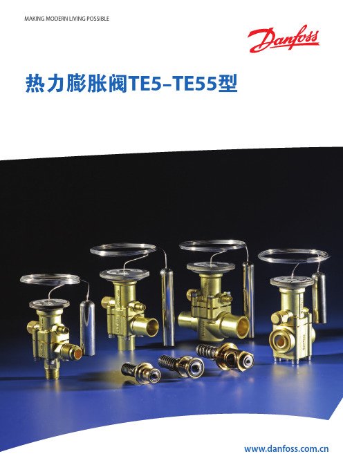
MAKING MODERN LIVING POSSIBLE热力膨胀阀TE5-TE55型引言 4特点 4技术数据 5过热度 5标识 5设计/功能 6订货 6 R134a 9 R404A/R507 11 R407C 15 R22 17尺寸及重量 21引言特点热力膨胀阀用于调节蒸发器中的液体制冷剂的供给量。
该供给量是通过制冷剂的过热度进行控制的。
可互换的热力感温原件使用丹佛斯著名的激光焊接技术,使用寿命更长。
新设计的流口组件冷量范围更加连续完整,应用范围更加广泛。
■蒸发温度范围大N系列-40℃至+10℃B系列-60℃至-25℃■可互换流口组件■不锈钢制的执行元件,毛细管和感温包■冷量范围宽■可提供MOP功能■精确的感温包充注■专利的感温包卡带设计■ MWP(最高工作压力)28 bar■冷量范围宽,冷量间隙和重叠小■ TE55具有平衡流口设计技术数据过热度■ 最高温度安装后,感温包承受的温度: 100℃未安装前阀的温度: 70℃■ 最低温度: -60℃■ 最高试验压力: 32 bar ■ 最高工作压力: 28 barMOP=最高运行压力SS :静态过热度OS :开启过热度SH :总过热度(SS + OS )Q nom :名义制冷量Q max : 最大制冷量举例静态过热度 SS = 4 K 开启过热度 OS = 4 K 总过热度 SH = 4 + 4 = 8 K静态过热度SS 可以使用调节杆来调节。
标准工厂过热度设置为4K 。
开启过热度OS = 4K 是阀开启至名义制冷量的开度时所对应的过热度。
使用B 系列流口组件时,如有必要,请确认运行工况下的过热度和重新调整过热度设置。
标识热力元件上贴有标签(在膜片装置的上方),上面标明阀所适用的制冷剂种类,例如:X = R22N = R134aS = R404A/R507Z = R407C同时,标签也标明了阀的型号、蒸发温度范围、MOP点,制冷剂以及最高试验压力和最高工作压力。
danfoss热力膨胀阀TUBTUC

Data sheetThermostatic expansion valve Type TUB/TUBE and TUC/TUCEIntroductionThe TU series of thermostatic expansion valves has been developed for soldering into hermetic refrigeration systems.TU valves are made of stainless steel and are therefore very suitable for use in the food industry.TU valves can be used in many forms of refrigeration systems, in particular:-Traditional refrigeration systems -Heat pump systems -Air conditioning units -Refrigeration appliances -Liquid coolers-Ice cube machines-Mobile refrigeration systemsAll variants are available in both single packs and industrial packs as required by the customer.TUB/TUBE have adjustable superheat and are available in angleway versions as standard.TUC/TUCE have fixed superheat, but are otherwise identical to TUB.TUB/TUBE and TUC/TUCE can be delivered in straightway versions.All straightway versions and TUC valves are produced to order and therefore this catalogue contains no description of a standard range or code numbers.TU valves are also available in a number of variants that give countless combination possibilities.Contact Danfoss for further information.Features·Bimetal connections-straightforward and fast soldering (no wet cloth or refrigeration pliers required).·RefrigerantsR 22, R 134a, R 404A, R 507, R 407C,R 410A and future refrigerants·Capacities from 0.6 to 16 kW (0.17 to 4.5 TR)for R 22-large capacity range in small steps ·Stable regulation·Biflow function (orifice 0 to 8)·Compact design- small dimensions and low weight ·Stainless steel, hermetically tight solder version-high connection strength -high corrosion resistance-capillary tube joints of high strength and vibration resistance·Laser-welded, stainless steel thermostatic diaphragm element -optimum function -long diaphragm life-high pressure resistance·Stainless steel double contact bulb -straightforward and fast installation -good heat transfer from bulb to pipe ·Adjustable superheat type (TUB/TUBE)-accurate setting-adjustable in operation·Fixed superheat type (TUC/TUCE)·Filter with high dirt retention capacity ·Available with self-cleaning bleed·Available with MOP (Max. Operating Pressure)Data sheet Thermostatic expansion valve, type TUB/TUBE and TUC/TUCEMax. bulb temperature100°C Max. valve body temperature 120°C,short-lived peak 150°CPermissible working pressure (excl. R 410A)PB =28 bar Max. working pressure, R 410A PB =42.5 bar Max. test pressure (excl. R 410A)p’ =36 bar Max. test pressure, R 410A p’ =47 barBiflow operationWith flow in the opposite direction, the rated capacity is reduced by up to 15%.TUBE with orifice 9, TUB and valves with MOP charges cannot be used for biflow operation.Technical dataMOP-pointsRange N Range NM Range B Refrigerant -40 ® +10°C -40 ® -5°C -60 ® -25°C MOP point for evaporating temperature t e and evaporating pressure p e 1)t e = +15°C/+60°F t e = 0°C/+32°F t e = -20°C/-4°F R 22p e = 100 psig/6.9 bar p e = 60 psig/4.0 bar p e = 20 psig/1.5 bar R 134ap e = 55 psig/3.9 bar p e = 30 psig/1.9 bar R 404A / R 507p e = 120 psig/8.4 bar p e = 75 psig/5.0 bar p e = 30 psig/2.0 bar R 407C p e = 95 psig/6.6 bar p e = 50 psig/3.6 bar p e =15 psig/1.1 bar R 410Ap e = 165 psig/11.5 bar p e = 100 psig/7.0 bar p e =45 psig/3.0 barTo avoid charge migration when MOP valves are used, the bulb temperature must be lower than the thermostatic element temperature.MOP valves1)p e in bar gaugeFor further information,please contact Danfoss.Capillary tube length: 1.5 m Bleed: 15%Connections:Inlet Orifice 0 ® 63/8 in./10 mm Orifice 7 ® 91/4 in./6 mm Straightway only1/2 in./12 mm Outlet3/8 in./10 mm Straightway only5/8 in./16 mmCapacity, orifice variants:In addition to the standard range, valves with orifice 0 are available for R 134a, R 404A and R 507.Variant rangeIn addition to the standard range, TUB/TUBE and TUC/TUCE valves are also available in these variants and variant combinations:Straightway versions Range N -40 ®+10°C MOP +15°C Range NM -40 ®-5°C MOP 0°C Range B -60 ®-25°C Range B–60 ®-25°CMOP -20°CStatic superheat (SS):2 K,3 K,4 K, or 6 K (applies to TUB/TUBE and TUC/TUCE – see fig. 5)Capillary tube length: 0.8 m Connections:Inlet Orifice 0 ® 61/4 in./6 mm Orifice 7 ® 93/8 in./10 mm Outlet1/2 in./12 mmStandard range Versions available in the standard range:Range N : -40 to +10°C without MOP Static superheat (SS):R 22, R 134a, R 404A, R 407C, R 410A = 5 K R 507 = 6.4 KData sheet Thermostatic expansion valve, type TUB/TUBE and TUC/TUCERange N = -40 ® +10 °CR 22, R 134a, R 404A/R 507Ordering AnglewaySupplied with bulb strap Standard valve rangeValves with inch connections have 1/4 in. pressure equalisation.Valves with mm connections have 6 mm pressure equalisation.1)Rated capacity Q nom. is based on:Evaporating temperature t e = +5°CCondensing temperature t c = +32°CRefrigerant liquid temperature t l = +28°COpening superheat OS = 4 K2)TUBE with orifice 9 and TUB (internal pressure equalisation)cannot be used for biflow operation.Refri-TypeRated Orifice Pres-Connection gerantcapacity no.2)sure Inlet ´ OutletQ nom. 1)equali-kW TR sation inch Code no.mm Code no.TUB 0.60.170int.1/4 ´ 1/2068U20566 ´ 12068U2036TUB 0.90.251int.1/4 ´ 1/2068U20576 ´ 12068U2037TUB 1.30.362int.1/4 ´ 1/2068U20586 ´ 12068U2038TUB 1.80.503int.1/4 ´ 1/2068U20596 ´ 12068U2039TUB 2.60.754int.1/4 ´ 1/2068U20606 ´ 12068U2040TUB 3.5 1.005int.1/4 ´ 1/2068U20616 ´ 12068U2041TUB 5.3 1.506int.1/4 ´ 1/2068U20626 ´ 12068U2042TUB 7.0 2.007int.3/8 ´ 1/2068U206310 ´ 12068U2043TUB 11.0 3.008int.3/8 ´ 1/2068U206410 ´ 12068U2044TUB 16.0 4.509int.3/8 ´ 1/2068U206510 ´ 12068U2045R 22TUBE 0.60.170ext.1/4 ´ 1/2068U20666 ´ 12068U2046TUBE 0.90.251ext.1/4 ´ 1/2068U20676 ´ 12068U2047TUBE 1.30.362ext.1/4 ´ 1/2068U20686 ´ 12068U2048TUBE 1.80.503ext.1/4 ´ 1/2068U20696 ´ 12068U2049TUBE 2.60.754ext.1/4 ´ 1/2068U20706 ´ 12068U2050TUBE 3.5 1.005ext.1/4 ´ 1/2068U20716 ´ 12068U2051TUBE 5.3 1.506ext.1/4 ´ 1/2068U20726 ´ 12068U2052TUBE 7.0 2.007ext.3/8 ´ 1/2068U207310 ´ 12068U2053TUBE 11.0 3.008ext.3/8 ´ 1/2068U207410 ´ 12068U2054TUBE 16.0 4.509ext.3/8 ´ 1/2068U207510 ´ 12068U2055TUB 0.70.191int.1/4 ´ 1/2068U20276 ´ 12068U2000TUB 1.00.282int.1/4 ´ 1/2068U20286 ´ 12068U2001TUB 1.40.393int.1/4 ´ 1/2068U20296 ´ 12068U2002TUB 2.10.594int.1/4 ´ 1/2068U20306 ´ 12068U2003TUB 2.70.785int.1/4 ´ 1/2068U20316 ´ 12068U2004TUB 4.1 1.206int.1/4 ´ 1/2068U20326 ´ 12068U2005TUB 5.5 1.607int.3/8 ´ 1/2068U203310 ´ 12068U2006TUB 8.2 2.308int.3/8 ´ 1/2068U203410 ´ 12068U2007TUB 12.0 3.509int.3/8 ´ 1/2068U203510 ´ 12068U2008R 134aTUBE 0.70.191ext.1/4 ´ 1/2068U20186 ´ 12068U2009TUBE 1.00.282ext.1/4 ´ 1/2068U20196 ´ 12068U2010TUBE 1.40.393ext.1/4 ´ 1/2068U20206 ´ 12068U2011TUBE 2.10.594ext.1/4 ´ 1/2068U20216 ´ 12068U2012TUBE 2.70.785ext.1/4 ´ 1/2068U20226 ´ 12068U2013TUBE 4.1 1.206ext.1/4 ´ 1/2068U20236 ´ 12068U2014TUBE 5.5 1.607ext.3/8 ´ 1/2068U202410 ´ 12068U2015TUBE 8.2 2.308ext.3/8 ´ 1/2068U202510 ´ 12068U2016TUBE 12.0 3.509ext.3/8 ´ 1/2068U202610 ´ 12068U2017TUB 0.70.191int.1/4 ´ 1/2068U20946 ´ 12068U2076TUB 1.00.282int.1/4 ´ 1/2068U20956 ´ 12068U2077TUB 1.40.393int.1/4 ´ 1 /2068U20966 ´ 12068U2078TUB 2.10.604int.1/4 ´ 1/2068U20976 ´ 12068U2079TUB 2.80.795int.1/4 ´ 1/2068U20986 ´ 12068U2080TUB 4.2 1.206int.1/4 ´ 1/2068U20996 ´ 12068U2081TUB 5.6 1.607int.3/8 ´ 1/2068U210010 ´ 12068U2082TUB 8.4 2.408int.3/8 ´ 1/2068U210110 ´ 12068U2083TUB 12.0 3.509int. 3/8 ´ 1/2068U210210 ´ 12068U2084R 404A TUBE 0.70.191ext.1/4 ´ 1/2068U21036 ´ 12068U2085R 507TUBE 1.00.282ext.1/4 ´ 1/2068U21046 ´ 12068U2086TUBE 1.40.393ext.1/4 ´ 1/2068U21056 ´ 12068U2087TUBE 2.10.604ext.1/4 ´ 1/2068U21066 ´ 12068U2088TUBE 2.80.795ext.1/4 ´ 1/2068U21076 ´ 12068U2089TUBE 4.2 1.206ext.1/4 ´ 1/2068U21086 ´ 12068U2090TUBE 5.6 1.607ext.3/8 ´ 1/2068U210910 ´ 12068U2091TUBE 8.4 2.408ext.3/8 ´ 1/2068U211010 ´ 12068U2092TUBE12.03.509ext.3/8 ´ 1/2068U211110 ´ 12068U2093Data sheet Thermostatic expansion valve, type TUB/TUBE and TUC/TUCER 407C, R 410ARange N = -40 ® +10 °CRefri-TypeRated Orifice Pres-Connection gerantcapacity no.2)sure Inlet ´ OutletQ nom. 1)equali-kW TR sation inch Code no.mm Code no.TUB 0.630.180int.1/4 ´ 1/2068U1920 6 ´ 12068U1900TUB 0.920.261int.1/4 ´ 1/2068U1921 6 ´ 12068U1901TUB 1.40.382int.1/4 ´ 1/2068U1922 6 ´ 12068U1902TUB 1.90.533int.1/4 ´ 1/2068U1923 6 ´ 12068U1903TUB 2.80.804int.1/4 ´ 1/2068U1924 6 ´ 12068U1904TUB 3.8 1.105int.1/4 ´ 1/2068U1925 6 ´ 12068U1905TUB 5.7 1.606int.1/4 ´ 1/2068U1926 6 ´ 12068U1906TUB 7.5 2.107int.3/8 ´ 1/2068U192710 ´ 12068U1907TUB 11.0 3.208int.3/8 ´ 1/2068U192810 ´ 12068U1908TUB 17.0 4.809int.3/8 ´ 1/2068U192910 ´ 12068U1909R 407CTUBE 0.630.180ext.1/4 ´ 1/2068U1930 6 ´ 12068U1910TUBE 0.920.261ext.1/4 ´ 1/2068U1931 6 ´ 12068U1911TUBE 1.40.382ext.1/4 ´ 1/2068U1932 6 ´ 12068U1912TUBE 1.90.533ext.1/4 ´ 1/2068U1933 6 ´ 12068U1913TUBE 2.80.804ext.1/4 ´ 1/2068U1934 6 ´ 12068U1914TUBE 3.8 1.105ext.1/4 ´ 1/2068U1935 6 ´ 12068U1915TUBE 5.7 1.606ext.1/4 ´ 1/2068U1936 6 ´ 12068U1916TUBE 7.5 2.107ext.3/8 ´ 1/2068U193710 ´ 12068U1917TUBE 11.0 3.208ext.3/8 ´ 1/2068U193810 ´ 12068U1918TUBE 17.0 4.809ext.3/8 ´ 1/2068U193910 ´ 12068U1919TUB 0.820.230int.1/4 ´ 1/2068U1798 6 ´ 12068U1796TUB 1.30.41int.1/4 ´ 1/2068U1958 6 ´ 12068U1940TUB 2.10.62int.1/4 ´ 1/2068U1959 6 ´ 12068U1941TUB 2.90.83int.1/4 ´ 1/2068U1960 6 ´ 12068U1942TUB 4.5 1.34int.1/4 ´ 1/2068U1961 6 ´ 12068U1943TUB 5.9 1.75int.1/4 ´ 1/2068U1962 6 ´ 12068U1944TUB 9.0 2.56int.1/4 ´ 1/2068U1963 6 ´ 12068U1945TUB 12.0 3.47int.3/8 ´ 1/2068U196410 ´ 12068U1946TUB 18.0 5.08int.3/8 ´ 1/2068U196510 ´ 12068U1947TUB 26.07.59int.3/8 ´ 1/2068U196610 ´ 12068U1948 R 410ATUBE 0.820.230ext.1/4 ´ 1/2068U1799 6 ´ 12068U1797TUBE 1.30.41ext.1/4 ´ 1/2068U1967 6 ´ 12068U1949TUBE 2.10.62ext.1/4 ´ 1/2068U1968 6 ´ 12068U1950TUBE 2.90.83ext.1/4 ´ 1/2068U1969 6 ´ 12068U1951TUBE 4.5 1.34ext.1/4 ´ 1/2068U1970 6 ´ 12068U1952TUBE 5.9 1.75ext.1/4 ´ 1/2068U1971 6 ´ 12068U1953TUBE 9.0 2.56ext.1/4 ´ 1/2068U1972 6 ´ 12068U1954TUBE 12.0 3.47ext.3/8 ´ 1/2068U197310 ´ 12068U1955TUBE 18.0 5.08ext.3/8 ´ 1/2068U197410 ´ 12068U1956TUBE26.07.59ext.3/8 ´ 1/2068U197510 ´ 12068U1957Valves with inch connections have 1/4 in. pressure equalisation.Valves with mm connections have 6 mm pressure equalisation.1)Rated capacity Q nom. is based on:Evaporating temperature t e = +5°CCondensing temperature t c = +32°CRefrigerant liquid temperature t l = +28°COpening superheat OS = 4 K2)TUBE with orifice 9 and TUB (internal pressure equalisation)cannot be used for biflow operation.Ordering AnglewaySupplied with bulb strap Standard valve rangeData sheet Thermostatic expansion valve, type TUB/TUBE and TUC/TUCER 22CapacityPressure drop across valve D p bar 246810121416Evaporating temperature 0°C 0.400.500.560.600.630.650.670.670.550.710.800.860.910.930.950.960.73 1.0 1.1 1.2 1.3 1.3 1.4 1.41.0 1.3 1.5 1.7 1.8 1.8 1.9 1.91.5 2.0 2.3 2.5 2.7 2.8 2.8 2.82.0 2.7 3.1 3.4 3.5 3.7 3.8 3.83.1 4.0 4.6 5.0 5.3 5.5 5.7 5.84.1 5.4 6.2 6.77.17.47.67.76.18.09.210.110.611.011.311.59.112.113.815.015.916.416.817.1Evaporating temperature -20°C 0.400.450.480.500.520.530.530.510.570.620.650.670.680.690.610.700.760.790.820.840.850.9 1.0 1.1 1.1 1.2 1.2 1.21.3 1.5 1.6 1.6 1.7 1.7 1.81.7 1.9 2.1 2.2 2.3 2.3 2.32.5 2.9 3.1 3.3 3.4 3.5 3.53.4 3.9 4.2 4.4 4.5 4.6 4.75.1 5.8 6.3 6.6 6.87.07.17.68.69.39.710.110.310.4Evaporating temperature -40°C 0.310.330.340.350.360.360.330.360.380.390.390.400.390.420.440.450.460.460.550.590.610.630.640.650.800.860.900.920.940.951.1 1.2 1.2 1.2 1.3 1.31.6 1.7 1.8 1.8 1.9 1.92.1 2.3 2.4 2.5 2.5 2.53.2 3.5 3.6 3.7 3.8 3.84.7 5.1 5.3 5.55.55.6Evaporating temperature -30°C 00.340.380.400.420.440.440.4510.390.450.480.510.520.530.5420.470.530.570.600.620.630.6330.660.740.800.840.870.880.894 1.0 1.1 1.2 1.2 1.3 1.3 1.35 1.3 1.5 1.6 1.7 1.7 1.7 1.86 1.9 2.2 2.4 2.5 2.5 2.6 2.67 2.6 2.9 3.2 3.3 3.4 3.5 3.58 3.9 4.4 4.8 5.0 5.1 5.2 5.395.76.57.07.37.57.77.7TypeOrifice Pressure drop across valve D p bar no.246810121416Evaporating temperature +10°C 00.420.530.600.650.680.700.710.7210.610.790.89 1.0 1.0 1.0 1.1 1.120.9 1.2 1.3 1.5 1.6 1.6 1.7 1.73 1.2 1.6 1.8 2.0 2.1 2.2 2.3 2.34 1.8 2.4 2.8 3.1 3.2 3.4 3.5 3.55 2.4 3.2 3.7 4.1 4.3 4.5 4.6 4.76 3.7 4.9 5.6 6.1 6.5 6.7 6.97.17 4.9 6.57.58.28.69.09.29.487.39.611.212.212.913.413.713.9910.914.516.718.219.320.020.520.9D t sub4 K10 K 15 K 20 K 25 K 30 K 35 K 40 K 45 K 50 K R 221.001.061.111.151.21.251.31.351.391.44Correction factor for subcooling D t subEvaporating temperature -10°C 00.360.460.510.550.570.590.600.6110.470.620.700.750.790.810.820.8320.600.780.89 1.0 1.0 1.1 1.1 1.130.8 1.1 1.3 1.4 1.4 1.5 1.5 1.54 1.2 1.6 1.9 2.0 2.1 2.2 2.2 2.35 1.7 2.2 2.5 2.7 2.8 2.9 3.0 3.06 2.5 3.2 3.7 4.0 4.3 4.4 4.5 4.67 3.3 4.3 5.0 5.4 5.7 5.9 6.0 6.18 5.0 6.57.58.18.58.89.09.197.49.711.112.012.613.113.313.5Capacity in kW for range N = -40 ® +10°C and opening superheat OS = 4 KTUTUTUNote:Insufficient subcooling can produce flash gas.Correction for subcooling D t subThe evaporator capacity used must be corrected if subcooling deviates from 4 K.The corrected capacity can be obtained by dividing the evaporator capacity by the correction factor given below.Since the expansion valve capacity must be equal to or slightly more than the corrected evaporator capacity of 2.7 kW, a TUB/TUBE with orifice 5 and a table capacity of 2.8 kW would be a suitable choice.Refrigerant = R 22Evaporating temperature t e = -10°C Pressure drop in valve D p = 10 bar Subcooling D t sub = 15 K Evaporator capacity = 3 kW Correction value (table) = 1.11The corrected evaporator capacity thus becomes 3 divided by 1.11 = 2.7 kWSelection exampleData sheet Thermostatic expansion valve, type TUB/TUBE and TUC/TUCECapacity (continued)Evaporating temperature -40°C 0.180.190.200.200.200.190.210.210.210.210.220.240.250.250.250.310.340.350.350.350.450.490.500.510.510.610.660.680.680.680.900.97 1.0 1.0 1.01.2 1.3 1.4 1.4 1.41.8 2.0 2.1 2.1 2.12.72.93.0 3.0 3.0Evaporating temperature -20°C 0.310.340.350.350.350.390.430.440.450.450.470.510.530.540.540.650.720.750.760.760.96 1.05 1.10 1.12 1.11.3 1.4 1.5 1.5 1.51.9 2.1 2.2 2.2 2.22.6 2.8 3.0 3.0 3.03.9 4.3 4.4 4.5 4.55.7 6.2 6.5 6.6 6.6Evaporating temperature -10°C 00.310.370.400.420.430.4310.410.510.550.580.580.5820.510.640.700.740.750.7630.710.890.98 1.0 1.1 1.14 1.1 1.3 1.5 1.5 1.6 1.65 1.4 1.8 2.0 2.1 2.1 2.16 2.1 2.7 2.9 3.1 3.1 3.27 2.8 3.5 3.9 4.1 4.2 4.28 4.3 5.3 5.9 6.2 6.3 6.39 6.37.98.79.19.39.3TypeOrifice Pressure drop across valve D p bar no.246810121416Evaporating temperature +10°C 00.380.460.500.530.540.5410.570.690.760.790.810.8120.82 1.1 1.2 1.2 1.3 1.33 1.1 1.4 1.6 1.7 1.8 1.84 1.7 2.2 2.5 2.6 2.7 2.75 2.3 2.9 3.3 3.5 3.6 3.66 3.4 4.4 4.9 5.2 5.4 5.57 4.6 5.9 6.67.07.27.28 6.88.79.810.310.610.8910.213.114.615.515.916.0D t sub4 K10 K 15 K 20 K 25 K 30 K 35 K 40 K 45 K 50 K R 134a1.001.081.131.191.251.311.371.421.481.54Correction factor for subcooling D t subPressure drop across valve D p bar 246810121416Evaporating temperature 0°C 0.350.420.460.480.490.490.500.610.660.690.700.710.660.840.930.98 1.0 1.00.92 1.2 1.3 1.4 1.4 1.41.4 1.8 1.9 2.0 2.1 2.11.8 2.3 2.6 2.7 2.8 2.82.8 3.5 3.9 4.1 4.2 4.33.7 4.7 5.2 5.5 5.6 5.75.57.07.88.28.48.58.310.411.512.212.412.5Evaporating temperature -30°C 00.250.270.280.280.2810.280.300.320.320.3220.320.350.370.370.3730.460.500.520.530.5240.670.730.760.770.7650.900.98 1.02 1.03 1.06 1.3 1.5 1.5 1.5 1.57 1.8 2.0 2.0 2.1 2.18 2.7 3.0 3.1 3.1 3.194.04.3 4.5 4.5 4.5Capacity in kW for range N = -40 ® +10°C and opening superheat OS = 4 KR 134aTUTUTUCorrection for subcooling D t subThe evaporator capacity used must be corrected if subcooling deviates from 4 K.The corrected capacity can be obtained by dividing the evaporator capacity by the correction factor given below.Note:Insufficient subcooling can produce flash gas.Data sheet Thermostatic expansion valve, type TUB/TUBE and TUC/TUCECapacity (continued)Pressure drop across valve D p bar246810121416Evaporating temperature 0°C 0.310.390.420.440.440.440.430.420.440.560.610.640.640.640.630.610.600.770.870.920.940.940.930.900.83 1.1 1.2 1.3 1.3 1.5 1.3 1.31.3 1.6 1.8 1.9 2.0 2.0 1.9 1.91.7 2.2 2.4 2.6 2.6 2.6 2.6 2.52.5 3.2 3.6 3.8 3.9 3.9 3.9 3.83.4 4.3 4.8 5.1 5.2 5.3 5.2 5.05.0 6.57.27.67.87.87.77.57.59.610.811.411.711.711.511.2TypeOrifice Pressure drop across valve D p bar no.246810121416Evaporating temperature +10°C 00.320.400.440.460.460.460.450.4410.470.600.680.690.700.700.680.6620.700.91 1.0 1.1 1.1 1.1 1.1 1.130.96 1.2 1.4 1.5 1.5 1.5 1.5 1.54 1.5 1.9 2.1 2.3 2.3 2.3 2.3 2.25 2.0 2.5 2.8 3.0 3.1 3.1 3.1 3.06 2.9 3.8 4.3 4.5 4.7 4.7 4.6 4.57 3.9 5.1 5.7 6.0 6.2 6.2 6.1 6.08 5.87.58.49.09.29.29.18.998.811.312.713.513.813.913.713.39Evaporating temperature -10°C 00.290.360.390.400.410.410.400.3910.390.500.540.570.570.570.560.5420.500.640.710.750.760.760.750.7330.700.890.99 1.0 1.1 1.1 1.1 1.04 1.0 1.3 1.5 1.6 1.6 1.6 1.6 1.55 1.4 1.8 2.0 2.1 2.1 2.1 2.1 2.06 2.1 2.7 3.0 3.1 3.2 3.2 3.1 3.17 2.8 3.6 4.0 4.2 4.3 4.3 4.2 4.18 4.2 5.3 5.9 6.3 6.4 6.4 6.3 6.19 6.27.98.89.39.59.59.39.0Evaporating temperature -20°C 0.320.350.360.360.360.350.340.410.460.480.480.480.470.450.510.560.590.600.600.590.570.710.790.830.840.840.820.801.1 1.2 1.2 1.2 1.2 1.2 1.21.4 1.6 1.6 1.7 1.7 1.6 1.62.1 2.3 2.4 2.5 2.5 2.4 2.42.8 3.1 3.3 3.3 3.3 3.3 3.24.3 4.7 4.9 5.0 5.0 4.9 4.86.36.97.37.47.47.27.0Evaporating temperature -30°C 00.30.310.310.310.30.2910.360.380.380.380.370.3620.430.450.450.450.440.4330.600.630.640.630.620.6040.890.930.940.930.910.885 1.2 1.2 1.3 1.2 1.2 1.26 1.8 1.9 1.9 1.9 1.8 1.87 2.4 2.5 2.5 2.5 2.4 2.48 3.6 3.7 3.8 3.8 3.7 3.695.3 5.5 5.5 5.55.45.2Evaporating temperature -40°C 0.240.250.250.250.240.230.270.280.280.280.270.260.320.330.330.330.320.310.450.460.470.460.450.430.650.680.680.670.660.630.880.910.910.900.880.851.3 1.4 1.4 1.3 1.3 1.31.8 1.8 1.8 1.8 1.8 1.72.6 2.7 2.8 2.7 2.7 2.63.9 4.0 4.0 4.03.93.7Capacity in kW for range N = -40 ® +10°C and opening superheat OS = 4 KR 404A/R507D t sub4 K 10 K 15 K 20 K 25 K 30 K 35 K 40 K 45 K 50 K R 404A/R 5071.001.11.21.291.371.46 1.54 1.63 1.7 1.78Correction factor for subcooling D t subTUTUTUCorrection for subcooling D t subThe evaporator capacity used must be corrected if subcooling deviates from 4 K.The corrected capacity can be obtained by dividing the evaporator capacity by the correction factor given below.Note:Insufficient subcooling can produce flash gas.Capacity (continued)Evaporating temperature -20°C 0.330.400.440.470.480.490.490.490.390.500.560.600.620.630.630.630.470.600.680.720.750.760.770.760.660.840.95 1.0 1.1 1.1 1.1 1.10.98 1.3 1.4 1.5 1.6 1.6 1.6 1.61.3 1.7 1.9 2.0 2.1 2.1 2.1 2.11.9 2.5 2.8 3.0 3.1 3.2 3.2 3.22.6 3.3 3.7 4.0 4.1 4.2 4.2 4.23.9 5.0 5.7 6.0 6.2 6.4 6.4 6.45.87.48.38.99.29.39.49.3Evaporating temperature -10°C 00.370.460.510.540.550.560.570.5610.480.620.700.740.760.770.770.7720.600.780.880.940.98 1.00 1.01 1.0130.84 1.1 1.2 1.3 1.4 1.4 1.4 1.44 1.3 1.6 1.8 2.0 2.0 2.1 2.1 2.15 1.7 2.2 2.4 2.6 2.7 2.8 2.8 2.86 2.5 3.2 3.7 3.9 4.1 4.2 4.2 4.27 3.4 4.3 4.9 5.2 5.5 5.6 5.6 5.68 5.0 6.57.47.98.28.48.48.497.59.610.911.612.112.312.412.4Pressure drop across valve D p bar246810121416Evaporating temperature 0°C 0.410.510.560.600.620.630.630.630.560.730.810.860.890.900.910.900.8 1.0 1.1 1.2 1.2 1.3 1.3 1.31.0 1.4 1.5 1.7 1.7 1.8 1.8 1.81.6 2.1 2.3 2.5 2.6 2.7 2.7 2.72.1 2.7 3.1 3.3 3.5 3.5 3.6 3.63.1 4.1 4.6 5.0 5.2 5.3 5.4 5.44.2 5.4 6.2 6.7 6.97.17.27.26.38.29.39.910.410.610.710.79.312.213.814.815.415.815.915.9TypeOrifice Pressure drop across valve D p bar no.246810121416Evaporating temperature +10°C 00.430.540.600.640.670.680.680.6810.630.810.900.960.99 1.01 1.02 1.0120.90 1.2 1.4 1.5 1.5 1.6 1.6 1.63 1.2 1.6 1.9 2.0 2.1 2.2 2.2 2.24 1.9 2.5 2.8 3.1 3.2 3.3 3.3 3.35 2.5 3.3 3.8 4.1 4.2 4.4 4.4 4.46 3.8 5.0 5.7 6.1 6.4 6.6 6.7 6.77 5.0 6.67.68.28.68.88.98.987.59.911.212.212.713.013.213.2911.314.816.918.219.019.519.719.7D t sub4 K10 K 15 K 20 K 25 K 30 K 35 K 40 K 45 K 50 K R 407C1.001.081.141.211.271.331.391.451.511.57Correction factor for subcooling D t subEvaporating temperature -40°C 0.290.310.320.320.320.310.310.330.340.340.350.340.360.380.400.400.400.400.510.540.560.560.560.560.750.790.810.820.820.821.0 1.1 1.1 1.1 1.1 1.11.5 1.6 1.6 1.6 1.6 1.62.0 2.1 2.2 2.2 2.2 2.23.0 3.2 3.3 3.3 3.3 3.34.4 4.7 4.8 4.94.9 4.8Evaporating temperature -30°C 00.260.290.310.320.320.320.3110.380.430.450.470.480.480.4720.450.500.530.550.560.560.5630.630.710.750.780.790.790.7940.93 1.0 1.1 1.1 1.2 1.2 1.25 1.3 1.4 1.5 1.5 1.6 1.6 1.56 1.9 2.1 2.2 2.3 2.3 2.3 2.37 2.5 2.8 3.0 3.1 3.1 3.1 3.18 3.8 4.2 4.5 4.6 4.7 4.7 4.79 5.5 6.2 6.5 6.7 6.86.9 6.8Capacity in kW for range N = -40 ® +10°C and opening superheat OS = 4 KR 407CTUTUTUCorrection for subcooling D t subThe evaporator capacity used must be corrected if subcooling deviates from 4 K.The corrected capacity can be obtained by dividing the evaporator capacity by the correction factor given below.Note:Insufficient subcooling can produce flash gas.Capacity (continued)R 410ATypeOrifice Pressure drop across valve D p bar Pressure drop across valve D p bar no.36912151821243691215182124Evaporating temperature +10°CEvaporating temperature 0°C Evaporating temperature -10°C Evaporating temperature -20°C Capacity in kW for range N = -40 to +10°C and opening superheat OS = 4 KEvaporating temperature -30°C Evaporating temperature -40°C D t sub4 K10 K15 K20 K25 K30 K 35 K 40 K 45 K 50 KR 410A1.00 1.08 1.15 1.21 1.27 1.33 1.39 1.45 1.50 1.56Correction factor for subcooling D t sub00.560.720.800.850.870.880.870.850.560.700.780.830.850.860.850.8410.89 1.13 1.26 1.30 1.37 1.38 1.36 1.330.84 1.06 1.18 1.24 1.29 1.30 1.29 1.272 1.45 1.90 2.2 2.3 2.4 2.5 2.4 2.4 1.25 1.64 1.86 1.99 2.1 2.1 2.1 2.13 1.98 2.6 3.0 3.2 3.3 3.3 3.3 3.3 1.72 2.3 2.6 2.7 2.9 2.9 2.9 2.94 3.1 4.1 4.6 4.9 5.1 5.2 5.1 5.0 2.6 3.5 3.9 4.2 4.3 4.4 4.4 4.3TU5 4.1 5.3 6.1 6.5 6.7 6.8 6.8 6.7 3.5 4.6 5.2 5.6 5.8 5.9 5.8 5.86 6.28.19.29.910.310.510.410.2 5.3 6.97.98.48.78.98.98.878.210.712.713.113.613.813.813.57.09.210.411.111.611.811.811.6812.115.818.019.320.020.320.219.910.413.715.516.617.217.517.517.2918.324.027.229.130.230.630.529.915.720.523.324.925.826.226.225.700.530.670.740.780.800.810.810.790.600.670.700.720.730.730.7210.760.96 1.07 1.13 1.16 1.17 1.17 1.150.830.920.97 1.00 1.01 1.000.992 1.04 1.35 1.52 1.63 1.69 1.72 1.72 1.70 1.06 1.20 1.28 1.32 1.34 1.34 1.333 1.44 1.86 2.1 2.3 2.3 2.4 2.4 2.4 1.48 1.67 1.78 1.84 1.87 1.87 1.854 2.2 2.8 3.2 3.4 3.5 3.6 3.6 3.5 2.2 2.5 2.7 2.7 2.8 2.8 2.8TU5 2.9 3.7 4.2 4.5 4.7 4.8 4.8 4.8 3.0 3.3 3.5 3.7 3.7 3.7 3.76 4.3 5.6 6.4 6.87.17.27.27.1 4.4 5.0 5.3 5.5 5.6 5.6 5.57 5.87.58.59.19.49.69.69.5 5.9 6.67.17.47.57.57.488.611.212.713.614.114.314.314.18.910.010.711.011.211.211.1912.916.819.020.321.021.321.321.013.214.815.816.416.616.616.400.520.580.610.630.630.630.620.480.500.520.520.520.5110.660.740.790.820.820.820.810.560.590.610.620.620.6120.810.900.96 1.00 1.01 1.01 1.000.660.700.720.730.730.723 1.13 1.27 1.35 1.40 1.41 1.41 1.400.930.98 1.02 1.03 1.03 1.014 1.67 1.87 2.0 2.1 2.1 2.1 2.1 1.36 1.45 1.49 1.51 1.50 1.48TU5 2.2 2.5 2.7 2.8 2.8 2.8 2.8 1.82 1.9 2.0 2.0 2.0 2.06 3.3 3.7 4.0 4.1 4.2 4.2 4.1 2.7 2.9 3.0 3.0 3.0 3.07 4.5 5.0 5.4 5.5 5.6 5.6 5.5 3.6 3.9 4.0 4.0 4.0 4.08 6.77.68.08.38.48.48.3 5.5 5.8 6.0 6.1 6.1 6.099.911.111.812.212.412.412.28.18.68.88.98.98.8Correction for subcooling D t subThe evaporator capacity used must be corrected if subcooling deviates from 4 K.The corrected capacity can be obtained by dividing the evaporator capacity by the correction factor given below.Note:Insufficient subcooling can produce flash gas.。
Danfoss热力膨胀阀样本参数
Danfoss A/S (RC-CM/hbs), 10 - 2002
RK0YP102
3
Introduction
Thermostatic expansion valves for ammonia type TEA
Thermostatic expansion valves regulate the injection of refrigerant liquid into evaporators. Injection is controlled by the refrigerant superheat.
Thermostatic injection valves, type TEAT
Introduction .............................................................................................................................. 11 Materials .................................................................................................................................. 11 Technical data .......................................................................................................................... 11 Identification ............................................................................................................................. 11 Ordering TEAT ......................................................................................................................... 12 Rated capacity in kW ............................................................................................................... 12 Extended capacities in kW ....................................................................................................... 13 Design/Function ....................................................................................................................... 13 Dimensions and weights .......................................................................................................... 14
ETS电子膨胀阀

温ŏ传感,
温ŏ传感,/ Pt 1000 ohm
AKS 11
Temp. Range
[℃]
Cable [m]
3.5
-50 +100
5.5
8.5
Code No.
084N0003 084N0006 084N0008
AKS 12
Temp. Range [℃]
-40 +80
Cable [m]
Quantity
• MOP 设ୱ • ࣯୧备य电౧
继电,输ෆ
• 报警
12 REFRIGERATION AND AIR CONDITIONING
丹佛斯控制器特点
ୢਨ
参数设,调试简单ࠇཥ
• ়ر参数ũ可过控,来设
13 REFRIGERATION AND AIR CONDITIONING
丹佛斯控制器特点
33
“
060G2101 060G2105 060G2049 060G2117
40
0 +80 060G2102 060G2106 060G2050 060G2118
55
“
060G2103 060G2107 060G2051 060G2119
Cable G 3/8 A
¼ Flare 060G2062
060G2065
ୢձ
2种过热ŏ控Ϸ܉ • ઞ适应过热ŏ/ඟخ稳态过热ŏ (ෆ厂设) • 负载ୱ义过热ŏ
ཥ业ʻ̩ඟ优ଝ过热ŏ控Ϸ܉
•• TThhrroouugghhSSHHsseeaarrcchhiningg,,rreeffeerreenncceeSSHH vvaalulueettoobbeelolowweerreeddttililllssuuccttioionntteemmpp.. hhaauunnttiningg
丹佛斯小型电子膨胀阀ETS6 技术资料英文
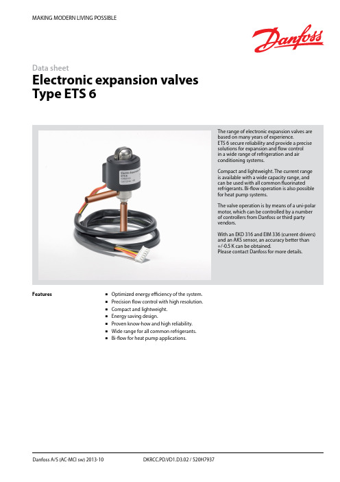
MAKING MODERN LIVING POSSIBLEDanfoss A/S (AC-MCI sw) 2013-10 DKRCC.PD.VD1.D3.02 / 520H7937Data sheetElectronic expansion valves Type ETS 6The range of electronic expansion valves are based on many years of experience.ETS 6 secure reliability and provide a precise solutions for ex p ansion and flow control in a wide range of refrigeration and air conditioning systems.Compact and lightweight. The current range is available with a wide capacity range, and can be used with all common fluorinated refrigerants. Bi-flow operation is also possible for heat pump systems.The valve operation is by means of a uni-polar motor, which can be controlled by a number of controllers from Danfoss or third party vendors.With an EKD 316 and EIM 336 (current drivers) and an AKS sensor, an accuracy better than +/-0.5 K can be obtained.Please contact Danfoss for more details.FeaturesOptimized energy efficiency of the system. Precision flow control with high resolution. Compact and lightweight. Energy saving design.Proven know-how and high reliability. Wide range for all common refrigerants. Bi-flow for heat pump applications.2DKRCC.PD.VD1.D3.02 / 520H7937Danfoss A/S (AC-MCI sw) 2013-10Data sheetElectronic Expansion Valves, type ETS 6Design/functionThe ETS 6 electronic expansion valves open and close to regulate refrigerant flow by means of a screw, whose rotating motion is transformed into linear motion. This occurs by the rotation of a magnet-needle valve assembly whichmoves when electrical signals are applied to the surrounding coil.Within the coil structure, there are different winding configurations, and the polarities arechanged by the electrical signals applied. By application of the appropriate combination of signals, in the form of pulses, the coil forces the rotor of the valve to move in a stepwise fashion.Application of multiple pulses will make the valve mechanism to move through a series of steps in the chosen direction, in order to set the valve with the required opening degree.CoilPermanent magnet motorNeedle valveValve bodyCross section diagram of ETS 6 series* Refers to refrigerant flow in cooling modeOutlet (A*)Inlet (B*)Technical dataFig. 1ApprovalsComplies with: EC PED 97/23/EC a3P3UL, RoHS and CQCRoHSData sheet Electronic Expansion Valves, type ETS 6Danfoss A/S (AC-MCI sw) 2013-10 DKRCC.PD.VD1.D3.02 / 520H79373Electrical wiringStepper motor switch sequenceThe illustration shows the JST XHP-6 connetor. The coil with JST XHP-5 is identical except that it does not have an unused pinCT=38°C, ET=5°C, SC=0°C, SH=0°C*Please contact Danfoss if higher maximum reverse pressure valve is required.1) Max. Reverse Pressure = Pressure as which the valve can still close tightly in reverse direction (from A to B see fig. 1).Valve ordering4 DKRCC.PD.VD1.D3.02 / 520H7937 Danfoss A/S (AC-MCI sw) 2013-10Data sheetElectronic Expansion Valves, type ETS 6For optimum performance, it is important to correct the evaporator capacity. In order toselect the correct size of ETS 6 you will need the following information:Refrigerant: HCFC or HFCEvaporator capacity Q e in kW or TR Evaporating temperature t e in °C or °F Condenser temperature t c in °C or °F Subcooling Δt sub in K or °F ExampleWhen selecting the valve it may be necessary to apply a correction factor to the actual evaporator capacity. This correction factor is required when system conditions are different than tableconditions. Selection also depends on having an acceptable pressure drop across the valve. In the selection table, the pressure drop in the liquid line is assumed to be zero. The following example illustrates correct selection of the valve.Refrigerant: R407CEvaporator capacity: Q e = 10 kW (2.84TR)Condensing temperature: t c = 40°C (104 °F) Evaporating temperature: t e = +10°C (50°F) Subcooling Δt sub = 10 KApplication exampleValve SelectionHeat pump components in typical system.1. Compressor.2. Controller.3. Four-way valve.4. Temperature sensor.5. Pressure transmitter.6. Cartridge pressure control.7. Evaporator.8. Condenser.9. Temperature sensor.10. Electronic expansion valve.11. Sight glass.12. Liquid line filter drier.Data sheetElectronic Expansion Valves, type ETS 6Danfoss A/S (AC-MCI sw) 2013-10 DKRCC.PD.VD1.D3.02 / 520H7937 5Step 1Determine the correction factor for subcooling Δt sub . From the correction factor table (see below) a subcooling of 10 K, R407C corresponds to a factor of 1.14.Correction factors for subcooling Δt sub .Step 2Corrected evaporator capacity isQ e (Corrected) = 10 kW/1.14 = 8.8 kW (2.5 TR)Step 3Select the appropriate capacity table, R407C, and choose the column for condensing temperature of t c = 40°C (104°F) and evaporating temperature of t e = 10°C (50°F) which will provide anequivalent or greater capacity of 8.8 kW (2.5 TR).ETS 6-18 provides 10.35 kW (2.94 TR), which is the proper selection for this example.Step 4Choose ETS 6-18:Single pack code no. 034G5026 I-pack code no. 034G5024Valve Selection (continued)Rated Capacity (kW)Correction factors for subcooling Δt subThe evaporator capacities used must be corrected if subcooling deviates from 0 K.The corrected capacity can be obtained bydividing the required evaporator capacity by the correction factor below. Selections can then bemade from the tables above.6 DKRCC.PD.VD1.D3.02 / 520H7937 Danfoss A/S (AC-MCI sw) 2013-10Data sheetElectronic Expansion Valves, type ETS 6Rated Capacity (kW)Rated Capacity (kW)Data sheetElectronic Expansion Valves, type ETS 6Danfoss A/S (AC-MCI sw) 2013-10 DKRCC.PD.VD1.D3.02 / 520H79377Rated Capacity (kW)Rated Capacity (kW)Data sheetElectronic Expansion Valves, type ETS 6Rated Capacity (kW)8 DKRCC.PD.VD1.D3.02 / 520H7937 Danfoss A/S (AC-MCI sw) 2013-10Data sheetElectronic Expansion Valves, type ETS 6Danfoss A/S (AC-MCI sw) 2013-10 DKRCC.PD.VD1.D3.02 / 520H79379Rated Capacity (TR)Rated Capacity (TR)10 DKRCC.PD.VD1.D3.02 / 520H7937 Danfoss A/S (AC-MCI sw) 2013-10Data sheetElectronic Expansion Valves, type ETS 6Rated Capacity (TR)Rated Capacity (TR)Data sheetElectronic Expansion Valves, type ETS 6Danfoss A/S (AC-MCI sw) 2013-10 DKRCC.PD.VD1.D3.02 / 520H793711Rated Capacity (TR)Rated Capacity (TR)Data sheet Electronic Expansion Valves, type ETS 6 Capacities, continuedConditionsR410 AT e: 5°CT c: 38°C Subcooling: 0°C Superheat: 0°C(B to A ref. drawing page 1)12 DKRCC.PD.VD1.D3.02 / 520H7937 Danfoss A/S (AC-MCI sw) 2013-10Data sheetElectronic Expansion Valves, type ETS 6Danfoss A/S (AC-MCI sw) 2013-10 DKRCC.PD.VD1.D3.02 / 520H7937 13DimensionsETS 6-10ETS 6-14ETS 6-25ETS 6-32ETS 6-40All dimensions in mmETS 6-18All dimensions in mmRelated Danfoss ProductsWeight: 0.16 kg (complete)。
丹佛斯机械热力膨胀阀产品介绍

REFRIGERATION AND AIR CONDITIONING
11
REFRIGERATION AND AIR CONDITIONING
12
Orifice assembly
REFRIGERATION AND AIR CONDITIONING
13
REFRIGERATION AND AIR CONDITIONING
Presetting on present version
7
TD1 Application
Market segments: • Refrigerators and Freezers • Water heat pump units • Vending machines • Glass Door Merchandiser • Bottle Coolers • Beer Dispensers • Electronics/Cabinet Cooling • Drinking Water & Cooler Fountains • Compressed Air Driers • Frozen Beverage Machines • Mobile Refrigerator & Freezer • Wine Cellar • Cold Rooms • Ice Maker
➢MWP: 42,5bar R410A 34bar excl. R410A
➢capacity:0,17 to 4,5 TR ➢Refrigerant range:
N: -40 to +10℃ NM: -40 to -5℃ B: -60 to -25℃
REFRIGERATION AND AIR CONDITIONING
TC Series
ETS 电子膨胀阀
-9-
RD1TA402 丹佛斯 A/S (RC-CMS/MWA),03-2005
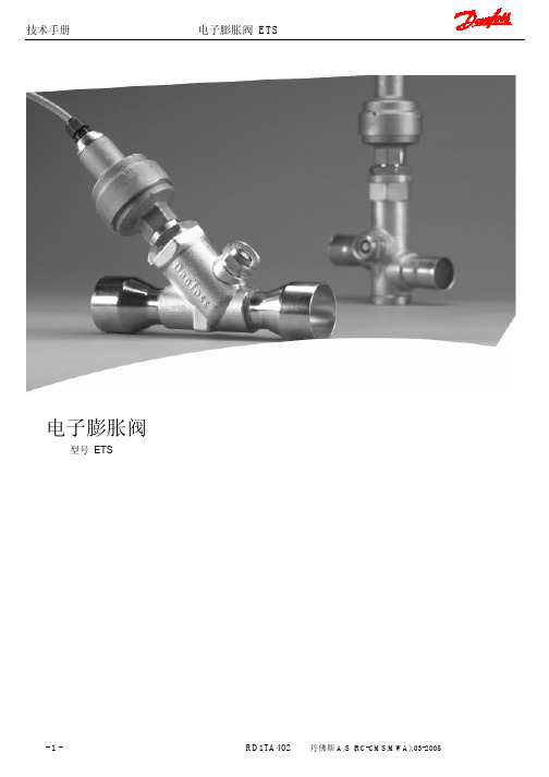
技术手册
制冷量 范围-40oF ~50oF
电子膨胀阀 ETS
额定制冷量 TR 阀两端压力降 Δp[psig]
US 单位制
过冷度修正系数 :当过冷度偏离 4K 时,蒸发器制冷量必须进行修正。修正制冷量为所需制冷量除以下表中 的修正系数。根据以上表格选择阀门型号。 注意:过冷度太低,会形成闪发蒸汽。
技术手册
制冷量 范围:-40℃~10℃
电子膨胀阀 ETS
额定制冷量 kW 阀两端压力降 Δp[巴]
SI 单位制
过冷度修正系数 :当过冷度偏离 4K 时,蒸发器制冷量必须进行修正。修正制冷量为所需制冷量除以下表中 的修正系数。根据以上表格选择阀门型号。 注意:过冷度太低,会形成闪发蒸汽。
修正系数
-8-
电机保护
IP67
参数 适用工质 CE 认证 MOPD 最大工作压力(PS/MWP) 制冷温度范围 环境温度 总行程 电机保护
ETS 250/ETS 400 HFC, HCFC 有 33bar(478.6psi) 34bar(493psi) -40℃to10℃(-40F to 50F) -40℃to60℃(-40F to 140F) 17.2mm(0.68in.) IP67
1. 电缆 2. 玻璃封口 3. AST 马达护盖 4. 步进马达 5. 轴承 6. 推杆 7. 填料 8. 活塞 9. 密封垫 10. 阀口
-4-
电子膨胀阀 ETS
线圈1
红
绿
+
-
+
-
-
+
-
+
+
-
ETS 50-400 双极永磁
丹佛斯膨胀阀tex参数

丹佛斯膨胀阀tex参数丹佛斯膨胀阀是一种用于调节制冷系统中制冷剂流量和压力的装置。
在制冷系统中,制冷剂需要通过膨胀阀实现从高压区域到低压区域的压力降低,从而实现制冷效果。
丹佛斯膨胀阀具有以下主要参数:额定制冷量(TR)、最大流通量(GPM)、额定减压率(PressureDrop Ratio)、额定工作温度(°F)和额定工作压力(psi)。
首先,额定制冷量是指膨胀阀能够处理的最大制冷量。
这个参数通常以吨(TR)为单位。
它与制冷系统的负载有关,因此在选择膨胀阀时,需要根据实际需要选择适当的额定制冷量。
其次,最大流通量是指单位时间内的制冷剂流动量。
它通常以加仑每分钟(GPM)为单位。
这个参数与制冷系统的冷却能力有关,因此在选择膨胀阀时需要考虑系统的最大流动量。
额定减压率是指膨胀阀在流量变化时所引起的制冷剂压力降低比例。
它通常以压力比例(Pressure Drop Ratio)来衡量。
膨胀阀的额定减压率越大,说明在流量变化时所引起的压力降低越大。
这个参数对于保证制冷系统的稳定运行非常重要。
额定工作温度是指膨胀阀能够正常工作的温度范围。
这个参数通常以华氏度(°F)为单位。
在选择膨胀阀时,需要确保额定工作温度覆盖到制冷系统中可能出现的最高温度。
最后,额定工作压力是指膨胀阀能够正常工作的压力范围。
这个参数通常以磅力每平方英寸(psi)为单位。
在选择膨胀阀时,需要确保额定工作压力覆盖到制冷系统中可能出现的最高压力。
综上所述,丹佛斯膨胀阀的参数包括额定制冷量、最大流通量、额定减压率、额定工作温度和额定工作压力。
这些参数对于选择合适的膨胀阀非常重要,以确保冷冻系统的正常运行和高效制冷效果。
- 1、下载文档前请自行甄别文档内容的完整性,平台不提供额外的编辑、内容补充、找答案等附加服务。
- 2、"仅部分预览"的文档,不可在线预览部分如存在完整性等问题,可反馈申请退款(可完整预览的文档不适用该条件!)。
- 3、如文档侵犯您的权益,请联系客服反馈,我们会尽快为您处理(人工客服工作时间:9:00-18:30)。
TEX 12
外平衡式2)
3
067B3232
067B3233
TEX 12
外平衡式2)
5
067B3363
TEX 20
外平衡式2)
3
067B3292
067B3293
TEX 20
外平衡式2)
5
067B3370
TEX 55
外平衡式2)
3
067G3222
067G3223
TEX 55
外平衡式2)
5
TEX 12
外平衡式2)
5
067B3209
067B3212
TEX 20
外平衡式2)
3
067B3274
067B3286
067B3276
TEX 20
外平衡式2)
5
067B3290
067B3287
TEX 55
外平衡式2)
3
067G3205
067G3220
067G3207
TEX 55
外平衡式2)
5
067G3209
丹佛斯膨胀阀
制冷剂
阀型号
压力
平衡方1)
毛细管
接口尺寸
产品代码
进口×出口
N系列
-40至+10℃
N系列
-40至-5℃
NL系列
-40至-15℃
NL系列
-60至-25℃
m
in.×in.
mm×mm
不带mop
带mop
带mop
带mop
不带mop
带mop
R22
TX 2
内平衡式
1.5
3/8*1/2
10*12
068Z3206
068Z3208
068Z3224
068Z3226
068Z3207
068Z3228
TEX 2
外平衡式
1.5
3/8*1/2
10*12
068Z3209
068Z3211
068Z3225
068Z3227
068Z3210
068Z3229
R134a
TN 2
内平衡式
1.5
3/8*1/2
10*12
068Z3346
068Z3347
068Z3393
068Z3369
TEN 2
外平衡式
1.5
3/8*1/2
10*12
068Z3348
068Z3349
068Z3392
068Z3370
R404A
/R507
TS 2
内平衡式
1.5
3/8*1/2
10*12
068Z3400
068Z3402
068Z3406
068Z3408
068Z3401
068Z3410
TES 2
外平衡式
1.5
3/8*1/2
10*12
068Z3403
068Z3405
068Z3407
068Z3409
068Z3404
068Z3411
R12
TF 2
内平衡式
1.5
3/8*1/2
10*12
068Z3202
068Z3236
068Z3220
068Z3222
TEF 2
外平衡式
1.5
3/8*1/2
10*12
TEX 55-50
239.0
148.0
01
067G2005
TEX 55-85
356.0
228.0
02
067G2006
热力感温元件
阀型号
压力平衡方式
毛细管
产品代码
N系列
-40至+10℃
NM系列
-40至-5℃
1/4in.6mm
m
不带MOP
带MOP
带MOP
TEX 5
外平衡式1)
3
067B3297
067B3298
0.15
0.11
0.5
0.38
068-2002
00
0.2
0.21
0.2
0.7
0.7
0.7
068-2003
01
0.3
0.45
0.3
1.0
1.6
1.0
068-2010
02
0.6
0.6
0.5
2.1
2.1
1.7
068-2015
03
0.8
1.0
0.8
2.8
3.5
2.8
068-2006
04
1.2
1.4
1.2
4.2
35.4
04
067B2092
TEX 12-4.5
26.8
17.2
01
067B2005
TEX 12-7.5
43.4
28.2
02
067B2006
TEX 12-12
64.0
41.4
03
067B2007
TEX 12-18
84.4
55.9
04
067B2008
TEX 20-30
108.0
70.0
01
067B2172
068Z3204
068Z3237
068Z3221
068Z3223
R502
TY 2
内平衡式
1.5
3/8*1/2
10*12
068Z3212
068Z3214
068Z3230
068Z3232
068Z3213
068Z3234
TEY 2
外平衡式
1.5
3/8*1/2
10*12
068Z3215
068Z3217
068Z3231
压力平衡方式
毛细管
产品代码
N系列
-40至+10℃
B系列
-60至-25℃
1/4in.6mm
m
不带MOP
带MOP
不带MOP
带MOP
TEX 5
外平衡式1)
3
067B3342
067B3344
067B3343
TEX 12
外平衡式2)
3
067B3347
067B3349
TEX 12
外平衡式2)
5
067B3346
067B3350
00
0.3
0.25
0.21
0.2
0.2
1.0
0.9
0.7
0.7
0.7
068-2003
01
0.7
0.5
0.45
0.3
0.3
2.5
1.8
1.6
1.0
1.0
068-2010
02
1.0
0.8
0.6
0.5
0.5
3.5
2.6
2.1
1.7
2.1
068-2015
03
1.5
1.3
1.2
1.0
1.0
5.2
4.6
4.2
3.5
068Z3233
068Z3216
068Z3235
N系列:-40℃至+10℃
流口编号
名义制冷量,单位:冷吨(TR)
名义制冷量,单位:KW
产品代码
R22
R134a
R404A
R507
R12
R502
R22
R134a
R404A
R507
R12
R502
0X
0.15
0.11
0.11
0.5
0.4
0.38
068-2002
3.5
068-2006
04
2.3
1.9
1.7
1.5
1.5
8.0
6.7
6.0
5.2
5.2
068-2007
05
3.0
2.5
2.2
2.0
2.0
10.5
8.6
7.7
7.0
7.0
068-2008
06
4.5
3.0
2.6
3.0
3.0
15.5
10.5
9.1
10.5
10.5
068-2009
B系列:-60℃至-25℃
0X
067G3230
流口组件
阀型号
名义制冷量N系列
KW
流口编号
产品代码
TEX 5-3.7
12.9
01
067B2089
TEX 5-5.4
19.1
02
067B2090
TEX 5-8.3
29.1
03
067B2091
TEX 5-11.2
39.6
04
067B2092
TEX 12-4.7
16.7
01
067B2005
TEX 12-7.7
27.2
02
067B2006
TEX 12-11.4
40.0
03
067B2007
TEX 12-15
53.0
04
067B2008
TEX 20-18
65.0
01
067B2170
TEX 55-41
145.0
01
067G2001
TEX 55-62
220.0
02
067G2002
热力感温元件
阀型号