substrate design trainning
PCB的名词解释
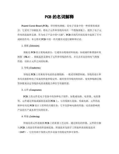
PCB的名词解释Printed Circuit Board (PCB),即印刷电路板,是电子设备中的一种重要组成部分。
它采用了印刷技术,将电子元件和导线布局在一个绝缘基板上,提供了电子元件间的连接和支撑。
作为电子产品中的“大脑”,PCB在现代科技发展中起到了不可或缺的作用。
本文将对PCB中的一些关键名词进行解释和讨论。
1. 基板 (Substrate)基板是PCB的主要构成部分,它通常由绝缘材料制成,如玻璃纤维增强环氧树脂(FR-4)。
基板起到支撑电子元件和导线的作用,并且具有良好的电气绝缘性能,以防止元件之间的短路。
2. 导线 (Conductor)导线是PCB上用来传导电流的金属线路,一般采用铜箔制成。
导线的设计和布局直接影响电子设备的性能和稳定性。
通常使用导线间的间距、宽度和线路层数等参数来决定导线的电流承载能力和信号传输性能。
3. 元件 (Component)PCB上的元件是电子设备中的各种电子部件,如集成电路、电容器、电阻器等。
元件通过焊接或插座连接到PCB上,与导线相互连接,形成电路。
元件的选择和布局是PCB设计工程师的关键任务,它不仅影响电路的性能,还直接影响到产品的生产成本和空间利用率。
4. 焊接 (Soldering)焊接是将元件连接到PCB上的重要工艺过程。
通过熔化的焊锡,元件的引脚与PCB上的涂有焊膏的焊盘相连接。
焊接技术包括手工焊接和表面贴装技术(SMT)。
它们有助于保持元件在设备中的稳定性和可靠性。
5. 系统集成 (System Integration)系统集成是指将多个PCB组装在一起,通过元件之间的连接和互联,构成复杂的电子系统。
系统集成是现代电子设备制造的重要环节,它不仅要求PCB间的准确布局和可靠连接,还需要满足信号传输的要求和整体性能的优化。
6. PCB设计 (PCB Design)PCB设计是制定PCB布局、连线和元件安装的过程。
在PCB设计中,设计工程师需要根据电路原理图、电气要求和尺寸限制,合理布局元件和导线。
IC封装设计与仿真

IC封装设计 设计实例:LGA(SMT+WB)
BlueTooth
IC封装设计 设计实例:BGA(SMT+Stacked 3 WB die)
CMMB sip
2.IC封装电磁仿真
封装电磁仿真
封装电磁仿真 PDS模型:
1. 片内电路信息(需要IC设计者提供RTL级信息以及相应的测试向量) 2. 片内去耦电容信息(IC设计者提供信息) 3. 片上电源地网格信息(IC设计者提供GDS格式信息) 4. 封装电源地信息和去耦电容信息 5. PCB上core电源地结构信息以及去耦电容信息 6. VRM
《IC封装设计与仿真》
内容
1.IC封装设计 2.封装电磁仿真 3.封装热仿真
4.封装结构仿真
1.IC封装设计
IC封装设计 IC封装内部结构:
塑封 芯片 金线 基板
1.模型提取(Model extraction),可提取IC封装 或PCB整板信号和电源的频域 阻抗参数和S参数,观测PDS的 谐振特性; 2.谐振点检测(Hot spot detection),可分析PDS随频 域变化的空间噪声分布和谐振 点分布; 3.EMC/EMI 辐射仿真 (EMC/EMI simulation),可 分析整板的远场和近场辐射.
Package Model对信号的影响
3.IC封装热仿真
封装热仿真 封装热仿真的必要性
封装热仿真
基本理论:热传递三种方式
传导
Q kA Tj Ta d
k 为材料导热系数(W/m-℃) A 为热传导面积 Tj 为高温面的温度 Ta 为低温面的温度 d 为材料厚度
直接从APD/Sip 设计文件提取封装的结 构,包括bond wire, trace,bump,solder ball等,用3D电磁场仿 真软件仿真RF端口的传 输参数并从结构上进行 传输特性的优化。
BGA专用英语
35. 36. 37. 38.
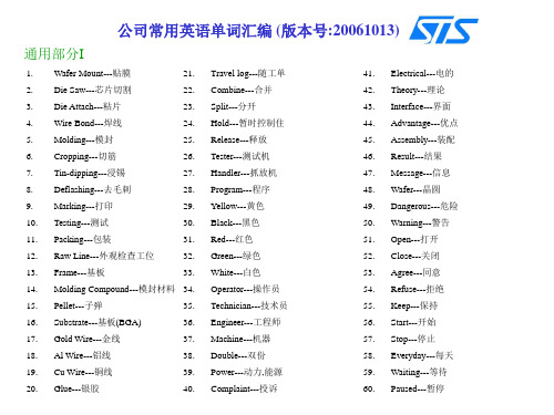
通用部分II
61. 62. 63. 64. 65. 66. 67. 68. 69. 70. 71. 72. 73. 74. 75. 76. 77. 78. 79. 80. Begin---开始 Other---其他 Setting---设置 Computer---电脑 Quantity---数量 Quality---质量 Parameter---参数 Monday---星期一 Tuesday---星期二 Wednesday---星期三 Thursday---星期四 Friday---星期五 Saturday---星期六 Sunday---星期日 Roster---倒班表 Morning---早晨 Afternoon---下午 Night---晚上 Shift---班次 Week---星期 81. 82. 83. 84. 85. 86. 87. 88. 89. 90. 91. 92. 93. 94. 95. 96. 97. 98. 99. 100. Month---月 Year---年 Sensor---传感器 Shuttle---往复装置 Empty---空的 Temperature—温度Normal---正常 Soak---浸泡 Yield---成品率 Magazine---盒子 Reject---拒收 Total---总的 Device---产品种类 Process---工艺 Scrap---废弃 Supervisor---领班 Superintendent---主管 Manager---经理 Idle---死机 Oven---烤箱 101. 102. 103. 104. 105. 106. 107. 108. 109. 110. 111. 112. 113. 114. 115. 116. 117. 118. 119. 120. WIP---待料 Cycle Time---循环时间 Material---物料 Continue---继续 Offload---下料 Onload---上料 End---结束 Jam---堵塞 Reverse---反转 Re-test---重测 Object---目标 Contact---接触 Light---灯光 Dark---黑暗 Air---空气 Stay---停留 Stray Units---散落的产品 Error---出错 Situation---情况 Key---钥匙
光刻缺陷检查培训英文版

Use a magnifying glass or microscope to magnify the surface of a wafer for more accurate identification and classification of defects. This method improves the accuracy and reliability of detection, but still requires manual operation.
Traditional defect inspection methods often have limitations in accuracy and efficiency, and cannot meet the needs of modern semiconductor manufacturing Therefore, it is necessary to provide training on literacy defect inspection to improve the ability of inspectors
workspace, and handling of the graphic substructure
02
Chemical factors
Residuals can be caused by the use of cancer chemicals during
processing that may not be completely removed from the
Analysis of lithography
IC封装设计与仿真
趋势:高集成度,高速,低 功耗,小型化。
IC封装设计 IC封装工艺(sip):SMT,DA,WB,Mold
IC封装设计 Substrate加工工艺:HDI,Buiding up
绿油 金层 镍层 铜层
通孔 埋孔 盲孔
PKG PCB
封装电磁仿真
PI:时域仿真
PI时域的仿真,对电源波动更加直观,我们可以提取正封装结构的S参, 或die-Package-PCB整个 PDN 的S参数到仿真器,加载上电流源电压源,仿真时域内电源的波动,并测量是否超限。
3.布局布线、平面分割优化: 电压压降分布、平面电流密度、平面功率密度
封装电磁仿真 PI:频域仿真
提取正封装结构,仿真真 个频域的电源阻抗,优化电容 数量和组合,提供最优的去耦 最低成本的电源完整性方案, 并可结合die与PCB做diePackage-PCB真个PDN的仿真。
1.模型提取(Model extraction),可提取IC封装 或PCB整板信号和电源的频域 阻抗参数和S参数,观测PDS的 谐振特性; 2.谐振点检测(Hot spot detection),可分析PDS随频 域变化的空间噪声分布和谐振 点分布; 3.EMC/EMI 辐射仿真 (EMC/EMI simulation),可 分析整板的远场和近场辐射.
FEM Model Directly?
Pin脚 晶体 RLC元件
IC封装设计
IC封装发展趋势:
芯片封装发展四阶段: 第一阶段,20世纪80年代前,以插装型为主; 第二阶段,20世纪80年代后,以表面安装类型的四边引线封装为主; 第三阶段,20世纪90年代后,以面阵列封装形式为主; 第四阶段,21世纪,3D封装为主。
pcb生产流程培训英文版

pcb生产流程培训英文版Here is the English essay on the topic of "PCB production process training" with a word count of over 1000 words:The production of printed circuit boards (PCBs) is a crucial process in the electronics industry, as these components serve as the backbone for a wide range of electronic devices, from smartphones to industrial equipment. Ensuring the proper training and understanding of the PCB production process is essential for maintaining high standards of quality and efficiency. In this essay, we will delve into the various stages of the PCB production process, providing a comprehensive overview for trainees and professionals alike.The first step in the PCB production process is the design phase. This involves the creation of a digital schematic or layout, which outlines the placement and interconnections of the various components that will be mounted on the board. The design phase requires a thorough understanding of electrical engineering principles, as well as the specific requirements and constraints of the intended application. Designers must consider factors such as component size, heat dissipation, and signal routing to ensure the PCB will function asintended.Once the design is complete, the next step is the fabrication of the PCB itself. This process begins with the creation of the base material, which is typically a thin, rigid substrate made of fiberglass or other insulating materials. The substrate is then coated with a thin layer of copper, which will serve as the conductive pathways for the electronic components. The copper layer is then etched away, leaving behind the desired circuit patterns.After the basic PCB structure has been created, the next step is the drilling process. This involves the use of specialized machinery to create the necessary holes and vias that will allow the components to be mounted and interconnected. The drilling process must be carried out with a high degree of precision, as the placement and size of these holes can have a significant impact on the overall performance and reliability of the PCB.Following the drilling process, the PCB undergoes a series of cleaning and preparation steps to ensure that the surface is ready for the next stage of production. This may include the application of a solder mask, which is a protective coating that helps to prevent short circuits and corrosion, as well as the application of a surface finish, such as gold or tin, to improve the solderability of the board.Once the PCB has been prepared, the next step is the component placement and soldering process. This involves the use of specialized equipment, such as pick-and-place machines, to accurately position the various electronic components on the board. The components are then secured in place using a process called soldering, which involves the melting of a metal alloy to create a strong, conductive bond between the component and the PCB.After the component placement and soldering process, the PCB undergoes a series of quality control checks to ensure that it meets the required standards for performance and reliability. This may include visual inspections, electrical testing, and even more advanced techniques such as automated optical inspection (AOI) and X-ray analysis.Finally, the completed PCB is packaged and prepared for shipment to the end customer. This may involve the addition of protective coatings, the installation of connectors or other hardware, and the labeling and documentation of the PCB.Throughout the entire PCB production process, it is essential that workers and trainees receive comprehensive training on the various techniques and equipment involved. This training should cover not only the practical aspects of the production process, but also the underlying principles and best practices that guide the industry. Byensuring that all personnel involved in the PCB production process are well-trained and knowledgeable, companies can ensure that their products meet the highest standards of quality and reliability.In conclusion, the PCB production process is a complex and multifaceted endeavor that requires a deep understanding of electrical engineering, materials science, and manufacturing techniques. By providing comprehensive training to all personnel involved in the process, companies can ensure that their PCBs are produced to the highest possible standards, helping to drive innovation and advancement in the electronics industry.。
cob陶瓷基板焊接时间

cob陶瓷基板焊接时间English.Ceramic-on-Board (COB) Substrate Soldering Duration.Factors Affecting COB Substrate Soldering Duration.The duration of COB substrate soldering is influenced by several key factors:Substrate Material: The thermal conductivity and heat capacity of the substrate material significantly impact the soldering time. Ceramics with higher thermal conductivity, such as alumina (Al2O3), allow for faster heat transfer and shorter soldering times compared to materials with lower thermal conductivity, such as zirconia (ZrO2).Substrate Thickness: Thicker substrates require longer soldering times to ensure proper heating and solder flow throughout the substrate.Soldering Method: Different soldering methods, such as reflow soldering, wave soldering, and laser soldering, have varying heating profiles and soldering times. Reflow soldering typically involves longer soldering times than other methods to ensure uniform heating and solder reflow across the substrate.Solder Paste Composition: The composition of the solder paste, including the type of solder alloy and flux content, can affect the soldering time. Solder alloys with lower melting temperatures, such as SAC305 (Sn-3Ag-0.5Cu), require shorter soldering times compared to alloys with higher melting temperatures.Component Size and Density: The size and density of components mounted on the COB substrate influence the soldering time. Larger components with higher power dissipation require longer soldering times to ensure adequate heat transfer and solder wetting.Substrate Design: The layout of components and traceson the COB substrate can affect the soldering time. Substrates with complex designs and dense component placement may require longer soldering times to ensure proper heating and solder flow.Soldering Equipment: The performance and capabilities of the soldering equipment, such as the solder paste printer, reflow oven, or laser soldering system, can impact the soldering time.Typical Soldering Duration Ranges.The typical soldering duration ranges for COB substrates vary depending on the specific factors mentioned above. However, as a general guide, the following ranges can be considered:Reflow Soldering: 60-120 seconds.Wave Soldering: 5-15 seconds.Laser Soldering: 1-5 seconds.It is important to note that these ranges are approximate and may vary depending on the specific application and requirements.Optimization of COB Substrate Soldering Duration.Optimizing the soldering duration for COB substrates involves understanding the factors that influence the soldering time and making adjustments to achieve the desired results. This includes:Selecting the appropriate substrate material and thickness for the specific application.Using the appropriate soldering method based on the component size and density.Choosing a solder paste composition that provides the required melting temperature and fluxing action.Optimizing the component layout and substrate designfor efficient heat transfer and solder flow.Calibrating the soldering equipment to ensure proper heating profiles and temperature control.By optimizing the soldering duration, manufacturers can achieve high-quality and reliable COB substrates with strong solder joints and minimal thermal stress.中文回答:陶瓷基板焊接时间。
[2]Excite Designer培训教程
![[2]Excite Designer培训教程](https://img.taocdn.com/s3/m/a4b3622c58fafab069dc02ea.png)
Training Course
概述 General
介绍 Introduction
EXCITE Designer 包括了发动机轴系初期设 计所需的工具,输入数据也较少。
covers tools required for crank train design analysis used early in the development process due to the small amount of data input required. The applications are:
EXCITE DESIGNER BTC-2003 10
模型准备 Model Preparation 活塞,销,连杆,轴承 Piston, Piston Pin, Connecting Rods, Bearings
可使用拷贝功能,包括活塞,连杆Use copy, create other pistons and connecting rods.
轴系参数Crank Train Globals:
Definition of Crank Train Main Characteristics
轴生成器Shaft Modeler:
Definition of Crank Shaft Characteristics
载荷数据Load Data:
Definition of Cylinder Pressure, Body Loads, External Loads
vibrations covers the calculation of natural frequencies as well as forced vibrations
z 强度计算Strength Calculation
- 1、下载文档前请自行甄别文档内容的完整性,平台不提供额外的编辑、内容补充、找答案等附加服务。
- 2、"仅部分预览"的文档,不可在线预览部分如存在完整性等问题,可反馈申请退款(可完整预览的文档不适用该条件!)。
- 3、如文档侵犯您的权益,请联系客服反馈,我们会尽快为您处理(人工客服工作时间:9:00-18:30)。
Chapter 2
显影
蚀刻
去菲林
印绿油
8/4/2003
曝光
Prepared by Neo Zhang
绿油显影
15
Substrate Design Training Manual
Substrate 的制造工艺(硬板4layer)
Chapter 2
电镀镍金
ii. Sandy & David should complete a PBGA 35x35 4 layer substrate design
iii. Sandy & Sophia should know how to check the substrate design and how to confirm the supplier’s Gerber.
ii. How to confirm the Gerber from the suppliers
iii. How to confirm the Fab Spec from the suppliers
Chapter 9: Drawing Management
i. How to submit you drawing
• Why we need the design rule
• How to use the design rule (RND-AB07)
Chapter 3-1: Substrate Material Spec
i. How to choose the material. (Core; P.P; S/R……)
ii. GAPT coding method
iii. What information should be backup in RND server
Chapter 10: Others
i. Everyone should complete a TFBGA 10x10 2 layer substrate design
Good Design
8/4/2003
Prepared by Neo Zhang
10
Substrate Design Training Manual
Chapter 1
How to get a good BGA package
Persons with ability
A Dependable Substrate Vender
16
Substrate Design Training Manual
Chapter 2
The raw material of a substrate
1.BT core: 双面覆铜板
芯板厚度 Core Thickness (mm)
芯板覆铜层厚度 Copper Clad (um)
材料名称 Material Name
Chapter 6: Post design
i. How to create the Gerber ii. How to check the Gerber iii. Make out the Fabrication Spec
Chapter 7: Customer
i. How to create substrate approved form ii. Why we need customer approve before we release it to
*0.4
12/12
HL832
注:*表示GAPT不建议使用之材料 Note: These materials are not suggested which marked with a “*”
8/4/2003
Prepared by Neo Zhang
BGA: Ball Grid Array (球栅阵列封装)
PBGA
FBGA
FCCSP
Super BGA 8/4/2003
CBGA Prepared by Neo Zhang
TBGA 7
Substrate Design Training Manual
Chapter 1
Other substrate type product
成型
Note: It’s only a typical flow. Since substrate fabrication is very complex. There are many different process in each substrate Fab.
8/4/2003
Prepared by Neo Zhang
8/4/2003
Prepared by Neo Zhang
2
Substrate Design Training Manual
Summary
Chapter 5: How to use the APD
i. How to setup the design rule in APD ii. How to Setup the options iii. How to setup the cross-section iv. How to create a customer die v. How to create a BGA vi. How to input the Net-list vii. How to set the DRC check viii. How to do the Auto W/B ix. How to align the fingers layout x. How to create the PWR/GND rings xi. How to arrange the vias xii. How to smooth the traces
iv. David should know how to complete a QFP design.
8/4/2003
Prepared by Neo Zhang
5
Substrate Design Training Manual
Chapter 1 About BGA Substrate (Introduction)
Chapter 2: Substrate Fabrication Process
• The raw material of a substrate
• The base Process flow of the substrate Fabrication
Chapter 3: Substrate Design Rule Introduce
8/4/2003
Prepared by Neo Zhang
3
Substrate Design Training Manual
Summary
xiii. How to create the teardrops xiv. How to setup the design rule in APD xv. How to run DRC check xvi. How to verify the design after the layout
1.一种信号的通路; 2.对芯片提供支撑; 3.散热的途径
8/4/2003
Prepared by Neo Zhang
9
Substrate Design Training Manual
Chapter 1
How to do a good design
Persons with ability Design Rule Design Database Tool (Design Software)
Substrate Design Training Manual
Summary
Chapter 1:About BGA Substrate (Introduction)
i. What is a BGA
ii. What is a substrate
iii. How to design a substrate
Fabrication? How to do get the approve.
8/4/2003
Prepared by Neo Zhang
4
Substrate Design Training Manual
Summary
Chapter 8: Substrate Supplier
i. What information we need to provide.
Design Database
A successful product
Equipments
8/4/2003
Prepared by Neo Zhang
11
Substrate Design Training Manual
Chapter 2 Substrate Fabrication Process
We need to know: • The raw material of a substrate • The base Process flow of the substrate
Fabrication
8/4/2003
Prepared by Neo Zhang
12
Substrate Design Training Manual
Substrate 的制造工艺(硬板4layer)
Chapter 2
双面覆铜板
贴干膜
曝光
显影
8/4/2003
蚀刻
Prepared by Neo Zhang
ii. The cross-section design of the substrate.
8/4/2003
Prepared by Neo Zhang
1
Substrate Design Training Manual