ANSYS有限元分析课程论文
基于ANSYS活塞有限元温度场的分析与研究
第一章绪论1.1内燃机活塞组有限元研究的背景和意义内燃机是目前世界上应用最广泛的热动力装置,它主要利用燃料燃烧释放出的热能产生有用的机械能做功。
经历了百余年的发展,内燃机领域己经取得了长足的进步。
在现今的社会中,几乎所有的交通工具均以内燃机做其核心的动力源。
回溯整个20世纪,内燃机技术的成熟推动了整个人类社会向前进步,其广泛的应用也造就了这个世纪的繁荣。
随着各种新技术的研究成果应用到发动机设计过程中,以及愈来愈严格的排放法规的现在,发动机正想着高转速,高功率和低油耗的方向发展。
功率的提高必然带来一些负面的影响。
如加重了活塞的热负荷,使得活塞的温度超过活塞材料所能承受的味道,大大降低了活塞磁疗的强度,严重时可能活塞会出现龟裂甚至烧损。
缸内爆发压力增加是活塞和缸体,缸盖承受的接卸符合增大。
可能导致活塞和缸体缸盖因强度不足而产生破坏。
此外压力升高率过大时,会产生敲缸现象,增加发动机的燃烧噪声,当提高发动机的转速以增大发动机的功率时,各个运动部件的惯性力也随着增加,使得活塞销和活塞销座的受力问题更为突出。
缸体对活塞的支撑力也增大。
于是发动机的噪声问题成为整车噪声中的主要问题【21】。
尽管转速的自己可以减少发动机的传热损失,但却同时造成发动机的NOx排放增加,在排放法规要求日益严格的今天,这一问题的得与失显得要慎重考虑。
不仅如此,还会造成摩擦损失的增加。
在满足发动机高功率设计的同时,必须要考虑发动机的温度和强度方面的要求。
发动机是一切动力装置的新章,而作为发动机关键部件的活塞又是重中之重,活塞热负荷和热强度问题的解决常常是提高征集技术水平的关键,直接影响内燃机工作可靠性和耐久性。
为了减少发动机的整机重量和提高功率,中小型柴油机几乎都采用铝合金作为材料,为了减少活塞的传热和热负荷,人们正尝试使用陶瓷作为活塞的材料。
有限元法是当今工程分析中应用最广泛的数值计算方法。
由于它的通用性和有效性,受到工程技术界的高度重视。
基于ANSYS有限元的热学力模拟分析全文

基于ANSYS有限元的热学力模拟分析全文第1章绪论1.1选题背景及意义随着时代的发展,现代各个领域包括船舶,航天等对于新型高分子纳米材料的诉求越来越高,基于这种背景下,石墨烯(G)和碳纳米管(CNTs)诞生了。
虽然二种材料从发明开始,就受到了极大的推崇,但是不能否认的是,它们也有一些缺陷,比如团聚现象;这一种现象在某些特殊的背景下应用,缺陷暴露的就更加明显了。
因此,必众多学者从本质上出发,根据二种材料的最外层电子为4的特性,从共价非共价改性进行探索,进而拓宽了二种材料的应用。
并且基于实际情况的需求,由于离子液体(ILs)一些优良性能,比如不易挥发等;完美的契合了这些实际情况的需求,并且ILs对于石墨烯材料以及碳纳米管材料有着很好地改良作用,进而进一步得到了推崇。
本文最大的创新就在于对于三者的综合应用,本文选用的离子液体是绿色溶剂离子液体,选用此溶剂是因为其对于石墨烯材料以及碳纳米管材料有着物理吸附作用,物理吸附可以不破外这些材料本身的化学结构,并且使得二种材料在基体中具有之前没有的特性:分散性,进而得到导电润滑脂。
这一新的研究,是一种三种元素结合起来的新的研究方向。
最后,把本文比较了ILs改性后和未改性后的二种高分子纳米材料作为润滑添加剂的各项性能。
1.2 石墨烯1.2.1 石墨烯的结构与性质对于石墨烯(G)这样一种新型高分子纳米材料而言,本质是碳原子组成的二维晶体,其各个维面是六边形蜂窝状。
首次发现是在21世纪初期,是由Novoselov[1]等通过胶带法首次获得的。
石墨烯具有一个特殊的离域大π键,其穿透了只有一个碳原子厚度的石墨烯。
这一特性使得石墨烯具有强度高,导电性好[2]、几乎完全透明、比表面积大[3]、载流子迁移率高[4]。
1.2.2石墨烯的制备方法对于石墨烯(G)获得的方法划分可以分为三种、石墨烯超声研磨法制取、石墨烯热剥离法制取、、石墨烯电化学法制取,三种方法具体情况如下:(1)超声研磨法第一种方法主要是根据超声波的原理,使得完整的石墨内部承受超过其承受能力的剪切应力,进而其二侧会造成缺陷,也就得到了石墨烯;该方法对于石墨的剥落产生了极大地便利。
ANSYS有限元分析课程论文
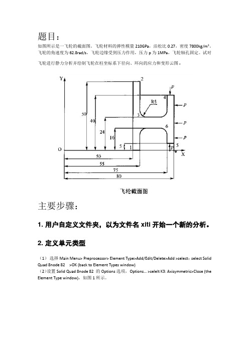
题目:如图所示是一飞轮的截面图。
飞轮材料的弹性模量210GPa,泊松比0.27,密度7800kg/m3。
飞轮的角速度为62.8rad/s,飞轮边缘受到压力作用,压力p为1MPa,飞轮轴孔固定。
试对飞轮进行静力分析并绘制飞轮在柱坐标系下径向、环向的应力和变形云图。
主要步骤:1. 用户自定义文件夹,以为文件名xiti开始一个新的分析。
2. 定义单元类型(1)选择Main Menu>Preprocessor> Element Type>Add/Edit/Delete>Add >select:select Solid Quad 8node 82 >OK (back to Element Types window)(2)设置Solid Quad 8node 82 的Options选项,Options… >selelt K3: Axisymmetric>Close (the Element Type window),如图1所示。
图1 单元属性设置对话框3. 定义材料性能参数(1)定义材料的弹性模量和泊松比Main Menu: Preprocessor >Material Props >Material Models >Structural >Linear >Elastic >Isotropic >input EX:2.10e5, PRXY:0.27 > OK(2)定义材料的密度Main Menu: Preprocessor >Material Props >Material Models>Favorite>Linear Static>Density >input DENS:0.0078 > OK4.建立几何模型、划分网格(1)生成特征点Main Menu>Preprocessor>Modeling>Create>Keypoints>In Active CS>依次输入点的坐标:input:1(50,0),2(55,0),3(55,16), 4(75,16), 5(75,5),6(80,5),7(80,40),8(75,40),9(75,24),10(55,24),11(55,50),12(50,50)(2)连接各特征点Main Menu>Preprocessor>Modeling>Create>Lines> Lines>Straight Line>依次连接各特征点:1(50,0),2(55,0),3(55,16), 4(75,16), 5(75,5),6(80,5),7(80,40),8(75,40),9(75,24),10(55,24),11(55,50),12(50,50)(3)生成过度圆弧Main Menu>Preprocessor>Modeling>Create>Lines>Line Fillet>选择需要产生过度圆弧的两边,输入过度圆弧的半径>OK 如图2所示。
有关有限分析ansys毕业论文
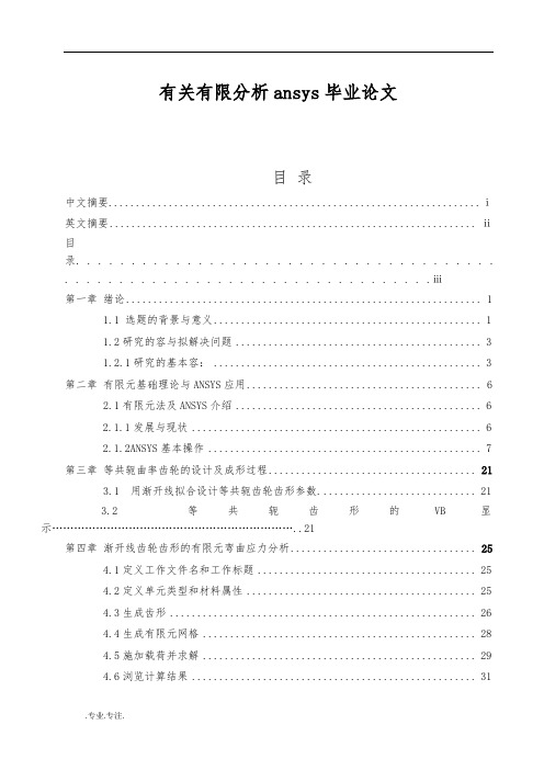
有关有限分析ansys毕业论文目录中文摘要 (ⅰ)英文摘要 (ⅱ)目录. . . . . . . . . . . . . . . . . . . . . . . . . . . . . . . . . . . . . .. . . . . . . . . . . . . . . . . . . . . . . . . . . . . . . . . .ⅲ第一章绪论 (1)1.1 选题的背景与意义 (1)1.2研究的容与拟解决问题 (3)1.2.1研究的基本容: (3)第二章有限元基础理论与ANSYS应用 (6)2.1有限元法及ANSYS介绍 (6)2.1.1发展与现状 (6)2.1.2ANSYS基本操作 (7)第三章等共轭曲率齿轮的设计及成形过程 (21)3.1 用渐开线拟合设计等共轭齿轮齿形参数. (21)3.2 等共轭齿形的VB显示 (21)第四章渐开线齿轮齿形的有限元弯曲应力分析 (25)4.1定义工作文件名和工作标题 (25)4.2定义单元类型和材料属性 (25)4.3生成齿形 (26)4.4生成有限元网格 (28)4.5施加载荷并求解 (29)4.6浏览计算结果 (31)4.7计算结果的验证 (34)第五章等共轭曲率齿形有限元弯曲应力分析 (38)5.1定义工作文件名和工作标题 (38)5.2定义单元类型和材料属性 (38)5.3生成齿形 (39)5.4生成有限元网格 (41)5.5施加载荷并求解 (42)5.6浏览计算结果 (43)5.7计算结果的验证 (44)第六章等共轭曲率齿轮的弯曲应力分析 (49)6.1等共轭曲率齿轮的建模 (49)6.2划分有限元网格 (50)6.3施加约束并求解分析 (51)第七章总结与展望 (54)参考文献 (55)致谢 (56)第一章绪论1.1 选题的背景与意义在不断研究与实践以及大量计算的基础上,用有限元分析高阶密切曲面和高阶密切齿面的弯曲应力,为高阶密切啮合理论的弯曲应力提供依据。
ansys论文(很好很全)

Ansys第二次大作业课程:有限元分析学生:马礼强学号:20087810组数: B 组班级:汽车一班指导老师:郭世伟精品文库第一题:1.题目杆件横截面积42810A m -=⨯,材料弹性模量102810/E N m =⨯。
(其中的JI=2m ,若图中有其它未给出的必要量值时,可自行取适当值)2、题目分析这是一个桁架问题,题设给出了桁架结构,杆长,杆件横截面积和材料弹性模量。
需对节点进行编号,建立模型,最后求解。
3、建模求解精品文库(1)、创建节点(2)建立模型(3)加载精品文库(4)结果分析1、变形情况精品文库2、轴向应力4轴向力5轴向应变6、列表显示的节点位移第二题:1、题目杆件横截面积42810A m -=⨯,材料弹性模量102810/E N m =⨯。
(其中的JI=2m ,若图中有其它未给出的必要量值时,可自行取适当值)2、题目分析此题为一悬臂梁问题,梁同时受均布力和集中力。
根据梁的长度和受理情况。
将梁划分为6个单元进行有限元分析。
3、建模求解 (1)、建立模型(2)、结果分析1、变形情况精品文库2、梁剪力3、梁弯矩精品文库4、列表显示各单元弯矩、剪力第三题:1、题目杆件横截面积42810A m -=⨯,材料弹性模量102810/E N m =⨯020/w kN m =L=4m 。
2、题目分析此题为一悬臂梁问题,梁同时受均布力和集中力。
根据梁的长度和受理情况。
将梁划分为10个单元进行有限元分析。
3、建模求解 (1)、建模2、结果分析1、变形结果精品文库2、梁剪力3、梁弯矩精品文库4、列表显示各单元弯矩、剪力精品文库附录:题一程序:/BATCH/COM,ANSYS RELEASE 12.1 UP20091102 10:26:52 05/11/2011/input,menust,tmp,'',,,,,,,,,,,,,,,,1/GRA,POWER/GST,ON/PLO,INFO,3/GRO,CURL,ON/CPLANE,1/REPLOT,RESIZEWPSTYLE,,,,,,,,0/UNITS,SI/PREP7ET,1,LINK1MP,EX,1,8E10R,1,8e-4N,1,0,0N,2,6,0N,6,4,8FILL,2,6N,11,6,8N,7,6,0FILL,7,11N,15,14,8FILL,11,15N,16,6,9N,19,12,9fill,16,19e,11,12EGEN,4,1,1,1,1e,2,3EGEN,4,1,5,5,1e,7,8EGEN,4,1,9,9,1e,11,17EGEN,3,1,13,13,1e,16,17EGEN,3,1,16,16,1e,11,16精品文库EGEN,4,1,19,19,1e,3,8EGEN,4,1,23,23,1e,3,9EGEN,3,1,27,27,1e,6,16e,15,19e,1,2e,1,6FINISH/SOLANTYPE,STATICOUTPR,BASIC,ALLD,1,ALL,0D,2,ALL,0F,15,FY,-1000F,14,FY,-2000F,13,FY,-1000SOLVED,7,ALL,0SOLVEFINISH/POST1PLDISP,1PRDISPETABLE,AXS,LS,1ETABLE,AXF,SMISC,1ETABLE,AXE,LEPEL,1PLETAB,AXS/REPLOT,RESIZEPLETAB,AXFPLETAB,AXEFINISHSA VEFINISH! /EXIT,MODEL题二程序:/BATCH/COM,ANSYS RELEASE 12.1 UP20091102 12:40:31 05/11/2011/input,menust,tmp,'',,,,,,,,,,,,,,,,1/GRA,POWER精品文库/GST,ON/PLO,INFO,3/GRO,CURL,ON/CPLANE,1/REPLOT,RESIZEWPSTYLE,,,,,,,,0/UNITS,SI/PREP7ET,1,BEAM3MP,EX,1,8E10R,1,0.001,0.002*0.5**3/12,0.5R,1,0.001,0.002*0.5**3/12,0.5N,1,0,0N,7,3,0FILL,1,7E,1,2EGEN,6,1,1,1,1FINISH/SOLUANTYPE,STATICOUTPR,BASIC,ALLD,1,ALL,0SFBEAM,1,1,PRES,900,900SFBEAM,2,1,PRES,900,900SFBEAM,3,1,PRES,900,900F,7,FY,-3000 SOLVEFINISHFINISH/post1PLDISP,1ETABLE,IM,SMISC,6ETABLE,JM,SMISC,12ETABLE,IS,SMISC,2ETABLE,JS,SMISC,8PRETABPLLS,IS,JSPLLS,IM,JMFINISHFINISH! /EXIT,MODEL题三程序:精品文库/BATCH/COM,ANSYS RELEASE 12.1 UP20091102 12:58:12 05/11/2011/input,menust,tmp,'',,,,,,,,,,,,,,,,1/GRA,POWER/GST,ON/PLO,INFO,3/GRO,CURL,ON/CPLANE,1/REPLOT,RESIZEWPSTYLE,,,,,,,,0/UNITS,SI/PREP7ET,1,BEAM3MP,EX,1,8E10R,1,0.001,0.002*0.5**3/12,0.5R,1,0.001,0.002*0.5**3/12,0.5N,1,0,0N,11,4,0FILL,1,11E,1,2EGEN,10,1,1,1,1FINISH/SOLUANTYPE,STATICOUTPR,BASIC,ALLD,1,ALL,0SFBEAM,1,1,PRES,0,400SFBEAM,2,1,PRES,400,800SFBEAM,3,1,PRES,800,1200SFBEAM,4,1,PRES,1200,1600SFBEAM,5,1,PRES,1600,2000SFBEAM,6,1,PRES,2000,1600SFBEAM,7,1,PRES,1600,1200SFBEAM,8,1,PRES,1200,800SFBEAM,9,1,PRES,800,400SFBEAM,10,1,PRES,400,0SOLVEFINISH/post1PLDISP,1ETABLE,IM,SMISC,6ETABLE,JM,SMISC,12ETABLE,IS,SMISC,2ETABLE,JS,SMISC,8精品文库PRETABPLLS,IS,JS/COLOR,WBAK,WHIT,1/COLOR,WBAK,BLAC,2/COLOR,WBAK,BLAC,3/COLOR,WBAK,BLAC,4/COLOR,WBAK,BLAC,5/REPLOT!*/COLOR,NUM,CY AN,1/COLOR,NUM,BMAG,2/COLOR,NUM,RED,3/COLOR,NUM,CBLU,4/COLOR,NUM,MRED,5/COLOR,NUM,GREE,6/COLOR,NUM,ORAN,7/COLOR,NUM,MAGE,8/COLOR,NUM,YGRE,9/COLOR,NUM,BLUE,10/COLOR,NUM,GCY A,11/REPLOT!*/COLOR,WBAK,BLAC,1/COLOR,WBAK,BLAC,2/COLOR,WBAK,BLAC,3/COLOR,WBAK,BLAC,4/COLOR,WBAK,BLAC,5/REPLOT!*PLLS,IM,JMFINISHFINISH! /EXIT,MODEL精品文库欢迎下载21。
基于ANSYS的吊钩有限元分析
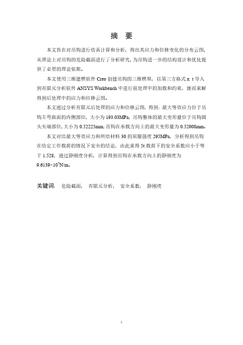
摘要本文旨在对吊钩进行仿真计算和分析,得出其应力和位移变化的分布云图,从理论上对吊钩的危险截面进行了分析研究,为吊钩进一步的结构设计和优化提供了必要的理论依据。
本文使用三维建模软件Creo创建吊钩的三维模型,以第三方格式x_t导入到有限元分析软件ANSYS Workbench中进行前处理中的加载和约束,继而求解得到后处理中的应力和位移云图。
本文通过分析有限元后处理的应力和位移云图,得到:最大等效应力位于吊钩主弯曲面的内侧部位,大小为193.03MPa;吊钩整体的最大变形量位于吊钩圆头尖端部位,大小为0.52225mm;吊钩在承载方向上的最大变形量为0.52008mm。
本文对比最大等效应力和所给材料30的屈服强度295MPa,分析得到吊钩在给定工作载荷的情况下安全的结论,由此求得5t载荷下的安全系数应小于等于1.528;通过静刚度分析,计算得到吊钩在承载方向上的静刚度为9.6139×10⁷N/m。
关键词:危险截面;有限元分析;安全系数;静刚度AbstractThe purpose of this paper is the simulation and analysis of the stress distribution of the hook, change of force and displacement, theoretically the dangerous section of the hook is analyzed, provide necessary theoretical basis for the further optimization of the structure design and the hook.Using three-dimensional modeling software Creo to create the 3D model of a hook, with the third party x_t format into finite element analysis software Workbench in the pretreatment of the loading and constraint, and then solve it to obtain the stress and displacement nephogram in postprocessing.In this paper, through the analysis of the finite element postprocessing of stress and displacement, get the maximum equivalent stress in the inner part of the hook main curved surface, the size of 193.03MPa; the maximum deformation of the whole hook tip in the hook head, the size of 0.52225mm; in the direction of the hook bearing the maximum deformation is 0.52008mm.This paper compares the maximum equivalent stress and the 30 material yield strength 295MPa, analysis safety hook in a given work load under the condition of the conclusions derived from the safety factor under the loading of 5t should be less than or equal to 1.528; through the analysis of static stiffness, the calculated in the direction of the hook bearing stiffness is 9.6139*107N/m.Key words: Dangerous section; Finite element analysis; safety factor;static stiffness摘要 (I)Abstract......................................................................................................................... I I 绪论.. (1)1 Creo软件建立吊钩三维模型 (2)1.1 Creo软件简介 (2)1.2 创建吊钩模型 (2)1.3 本章小结 (17)2 吊钩有限元分析 (17)2.1 ANSYS有限元软件介绍 (17)2.1.1 ANSYS简介 (17)2.1.2 ANSYS平台选用 (18)2.2 前处理 (18)2.2.1 导入模型 (18)2.2.2 模型优化 (19)2.2.3 网格划分 (21)2.2.4 施加载荷 (24)2.2.5 添加材料 (24)2.3 求解及后处理 (25)2.3.1 求解 (25)2.3.2 后处理云图 (26)2.4 本章小结 (28)3 结论 (28)3.1 有限元分析结果 (28)3.2 吊钩强度分析和安全系数 (28)3.3 吊钩静刚度分析 (29)3.4 全文总结 (29)参考文献 (31)在国民经济建设中,吊钩是必不可少的技术装备,它在城市建设、交通运输、农田水利、能源开发和国防建设等各方面都起着十分重要的作用[1]。
课程设计ANSYS有限元分析(最完整)
有限元法分析与建模课程设计报告学院 : 机电学院专业:机械制造及其自动化指导教师: ****学生: * ***学号 :2012011****2015-12—31摘要本文通过ANSYS10。
0建立了标准光盘的离心力分析模型,采用有限元方法对高速旋转的光盘引起的应力及其应变进行分析,同时运用经典弹性力学知识来介绍ANSYS10。
0中关于平面应力问题分析的基本过程和注意事项。
力求较为真实地反映光盘在光驱中实际应力和应变分布情况,为人们进行合理的标准光盘结构设计和制造工艺提供理论依据.关键词:ANSYS10.0;光盘;应力;应变。
目录第一章引言 (1)1。
1 引言 (1)第二章问题描述 (2)2.1有限元法及其基本思想 (2)2.2 问题描述 (2)第三章力学模型的建立和求解 (2)3。
1设定分析作业名和标题 (3)3。
2定义单元类型 (4)3.3定义实常数 (7)3。
4定义材料属性 (9)3。
5建立盘面模型 (11)3。
6对盘面划分网格 (19)3.7施加位移边界 (23)3.8施加转速惯性载荷并求解 (26)第四章结果分析 (28)4。
1 旋转结果坐标系 (28)4。
2查看变形 (29)4。
3查看应力 (31)总结 (35)参考文献 (35)第一章引言1.1 引言光盘业是我国信息化建设中发展迅速的产业之一,认真研究光盘产业的规律和发展趋势,是一件非常迫切的工作。
光盘产业发展的整体性强,宏观调控要求高,因此,对于光盘产业的总体部署、合理布局和有序发展等问题,包括节目制作、软件开发、硬件制造、节目生产、技术标准等。
在高速光盘驱动器中,光盘片会产生应力和应变,在用ANSYS分析时,要施加盘片高速旋转引起的惯性载荷,即可以施加角速度。
需要注意的是,利用ANSYS施加边界条件时,要将内孔边缘节点的周向位移固定,为施加周向位移,而且还需要将节点坐标系旋转到柱坐标系下.本文通过ANSYS10.0建立了标准光盘的离心力分析模型,采用有限元方法对高速旋转的光盘引起的应力及其应变进行分析,同时运用经典弹性力学知识来介绍ANSYS10。
ANSYS有限元设计方法论文
ANSYS有限元设计方法论文摘要:有限元软件ANSYSY可以很好地用于结构力学分析,有助于减轻学习难度、增强学生对结构力学特性的感性认识,帮助学生认识和理解结构力学的理论和方法,培养学生实际动手能力、实际解决问题的能力和科研创造能力。
力学分析是机械、建筑等工科类学生的设计、学习的基础课程,力学分析主要包括刚度、强度、稳定性等方向的研究[1]。
由于实验条件的限制,学生对理论方面的理解比较困难,通过有限元分析软件ANSYS进行模拟仿真,可以直观地了解结构在载荷作用下的变化情况。
因此,可以借助CAE仿真软件进行数值计算,作为辅助教学手段,以薄板圆孔的应力分析为例,为常规教学方式的进提供依据。
1 薄板圆孔应力分析的理论基础已知一个承受内压的薄板,在其中心位置有一个小圆孔,相关的结构尺寸如图1所示,根据对称性,可取圆筒的四分之一并施加垂直于对称面的约束进行分析。
材料的弹性模量E=2e11PaKN/m2,泊松比为0.3,拉伸载荷q=3000Pa,平板的厚度t=0.01mm。
圆孔的径向应力σr和切向应力σt沿半径r方向的分布,根据材料力学的知识,σr 和σt沿r方向分布的解析解为[4],图1 薄板结构受力图2 薄板圆孔的有限元分析文章运用有限元分析软件ANSYS对薄板圆孔进行有限元静力学分析,划分薄板圆孔的网格第一步工作。
网格划分采用边线单元尺寸控制,桅杆约划分为400个单元,其划分网格后的有限元模型如图2所示[5-6]。
在静力学分析过程中由于压力施加在圆孔边缘,分别对圆孔所在的两边施加x和y的位移约束,同时对圆孔边缘施加3000Pa的压强,如图3所示,观察桅杆结构的应力分布情况;然后通过ANSYS软件计算整体变形情况。
四分之一薄板位移云图、节点的Von-Mise应力云图和整体薄板位移云图、节点的Von-Mise应力云图如图4、图5所示。
从图4、图5中可以看出薄板圆孔在3000Pa压力作用下的位移变化和受力分布情况。
机械毕业设计(论文)基于ansys的连杆机构的有限元分析【全套设计】
湘潭大学兴湘学院毕业设计论文题目:连杆机构的有限元分析全套设计,加153893706专业:机械设计制造及其自动化学号: 2010963028 姓名:指导教师:完成日期: 2014 年 5 月 25 日湘潭大学兴湘学院毕业论文(设计)任务书论文(设计)题目:连杆机构的有限元分析学号: 2010963028姓名:专业:机械设计制造及其自动化指导教师:系主任:一、主要内容及基本要求1、总结连杆机构设计方法研究和连杆机构研究的发展状况和发展趋势,在总结前人研究成果的基础上,结合当前的技术发展趋势,采用有限元方法来进行开展研究。
2、阐述学习理论基础,即瞬态动力学分析,简要论述瞬态参数,识别原理。
3、简要论述有限元方法和动力学分析的基本求解过程,建立连杆机构中的曲柄滑块机构的有限元模型,合理的确定曲柄长度及转速、连杆长度和转速,偏距,选定和创建单元类型,指点单元属性,创建铰链单元,采用瞬态动力学分析瞬态分析类型对其进行瞬态分析,与图解法进行比较,验证有限元瞬态求解功能。
4、联系工程实际,对受力连杆进行结构静力学学习。
二、重点研究的问题1、 ANSYS的线性静力分析2 、构建几何模型3、在三维铰链单元COMBIN7的创建4、单元类型选择和网络划分5、 ANSYS瞬态动力学分析和静力学分析三、进度安排四、应收集的资料及主要参考文献[1]高耀东,刘学杰.ANSYS机械工程应用精华50例(第三版).- 北京:电子工业出版社,2011.[2]孙波.毕业设计宝典.-西安:西安电子科技大学出版社,2008.[3]温正,张文电.ANSYS14.0有限元分析权威指南.-北京:机械工业出版社,2013.[4]欧阳周,汪振华,刘道德.毕业论文和毕业设计说明书写作指南.-长沙:中南工业大学出版社,1996.[5]华大年,华志宏.连杆机构设计与应用创新.-北京:机械工业出版社,2008.[6]胡仁喜,康士廷.机械与结构有限元分析从入门到精通.-北京:机械工业出版社,2012.[7]李红云,赵社戌,孙雁.ANSYS10.0基础及工程应用.北京:机械工业出版社,2008.[8]唐家玮,马喜川.平面连杆机构运动综合.-哈尔滨:哈尔滨工业大学出版社,1995.[9]潘存云,唐进元.机械原理.-长沙:中南大学出版社,2011.[10]李皓月,周田朋,刘相新.ANSYS工程计算应用教程.-北京:中国铁道出版社,2003湘潭大学兴湘学院毕业论文(设计)评阅表学号2010963028 姓名谭磁安专机械设计制造及其自动化毕业论文(设计)题目:连杆机构的有限元分析湘潭大学兴湘学院毕业论文(设计)鉴定意见学号2010963028 姓名谭磁安专业机械设计制造及其自动化毕业论文77 页图表30 张目录摘要............................................................................................ 错误!未定义书签。
基于ANSYS的轴的有限元分析
基于ANSYS的轴的有限元分析ANSYS是一种用于工程分析的有限元分析软件,可以用来解决各种结构和物理问题。
在这篇文章中,我将介绍如何使用ANSYS进行轴的有限元分析。
在轴的有限元分析中,我们需要首先创建轴的几何模型。
通过ANSYS的建模工具,我们可以创建轴的几何形状,包括直径、长度和端部的约束条件。
接下来,我们需要定义轴的材料特性。
可以通过ANSYS的材料库选择适当的材料,并输入其弹性模量和泊松比等参数。
在进行有限元分析之前,我们需要将轴的几何模型离散化为有限元素。
可以使用ANSYS的网格划分工具,将轴划分为多个有限元。
划分的精度和密度可以根据实际需求进行调整。
在进行有限元分析之前,我们需要定义加载条件。
轴可以受到各种不同类型的载荷,如压力、拉力或扭矩。
可以使用ANSYS的加载工具,将这些载荷应用于轴的相应位置。
完成了网格划分和加载条件定义后,我们就可以进行有限元分析了。
根据所选的分析类型,可以使用ANSYS的求解器来解决轴上的力、位移和应力等问题。
ANSYS提供了不同的求解器,如静力学求解器、热力学求解器和动力学求解器等。
在有限元分析完成后,我们可以检查分析结果并进行后处理。
可以使用ANSYS的后处理工具,查看轴上的位移、应力和应变分布。
还可以绘制图表和动画,以更好地理解分析结果。
最后,我们可以通过修改材料或几何参数,重新运行有限元分析,以评估不同设计方案的性能。
ANSYS的参数化设计功能可以帮助我们自动化这个过程,快速评估多个方案。
总之,基于ANSYS的轴的有限元分析是一种强大的工程分析方法,可以帮助我们了解轴的力学特性,并进行设计优化。
通过使用ANSYS的建模、求解和后处理工具,我们可以准确地预测轴的行为,并为轴的设计提供有力支持。
- 1、下载文档前请自行甄别文档内容的完整性,平台不提供额外的编辑、内容补充、找答案等附加服务。
- 2、"仅部分预览"的文档,不可在线预览部分如存在完整性等问题,可反馈申请退款(可完整预览的文档不适用该条件!)。
- 3、如文档侵犯您的权益,请联系客服反馈,我们会尽快为您处理(人工客服工作时间:9:00-18:30)。
题目:
如图所示是一飞轮的截面图。
飞轮材料的弹性模量210GPa,泊松比0.27,密度7800kg/m3。
飞轮的角速度为62.8rad/s,飞轮边缘受到压力作用,压力p为1MPa,飞轮轴孔固定。
试对
飞轮进行静力分析并绘制飞轮在柱坐标系下径向、环向的应力和变形云图。
主要步骤:
1.用户自定义文件夹,以为文件名xiti开始一个新的分析。
2.定义单元类型
(1)选择Main Menu>Preprocessor> Element Type>Add/Edit/Delete>Add >select:select Solid Quad 8node 82 >OK (back to Element Types window)
(2)设置Solid Quad 8node 82 的Options选项,Options… >selelt K3: Axisymmetric>Close (the Element Type window),如图1所示。
图1 单元属性设置对话框
3.定义材料性能参数
(1)定义材料的弹性模量和泊松比
Main Menu: Preprocessor >Material Props >Material Models >Structural >Linear >Elastic >Isotropic >input EX:2.10e5, PRXY:0.27 > OK
(2)定义材料的密度
Main Menu: Preprocessor >Material Props >Material Models>Favorite>Linear Static>Density >input DENS:0.0078 > OK
4.建立几何模型、划分网格
(1)生成特征点
Main Menu>Preprocessor>Modeling>Create>Keypoints>In Active CS>依次输入点的坐标:input:1(50,0),2(55,0),3(55,16), 4(75,16), 5(75,5),6(80,5),7(80,40),8(75,40),
9(75,24),10(55,24),11(55,50),12(50,50)
(2)连接各特征点
Main Menu>Preprocessor>Modeling>Create>Lines> Lines>Straight Line>依次连接各特征点:1(50,0),2(55,0),3(55,16), 4(75,16), 5(75,5),6(80,5),7(80,40),8(75,40),
9(75,24),10(55,24),11(55,50),12(50,50)
(3)生成过度圆弧
Main Menu>Preprocessor>Modeling>Create>Lines>Line Fillet>选择需要产生过度圆弧的两边,输入过度圆弧的半径>OK 如图2所示。
图2 飞轮截面形状
(4)生成飞轮截面
Main Menu>Preprocessor>Modeling>Create>Areas>Arbitrary>By lines>依次选择各条线>OK 如图3所示。
图3 飞轮截面模型
5.网格划分
Main Menu>Preprocessor >Meshing >Mesh Tool > (Size Controls) Global: Set >input SIZE:1 >OK
Mesh Tool >Mesh : select Areas> Shape:Quad>Free > Mesh > Pick All >Close( the
Mesh Tool window) 如图4所示。
图4 飞轮网格划分模型
6.模型约束加载
(1)对飞轮边施加位移约束
Main Menu>Solution >Define Loads >Apply >Structural >Displacement > On Lines >拾取左边> OK > select Lab2:ALL DOF > OK
(2)对飞轮边施加载荷
Main Menu>Solution >Define Loads >Apply >Structural >Pressure> On Lines >选择图示的三条边>如下图5输入>OK
图5 飞轮边施加载荷
(3)施加角速度
ANSYS Main Menu: Solution >Define Loads >Apply >Structural >Inertia > Angular veloc >Globel弹出施加角速度的对话框,如图6输入
图6 施加角速度
7.分析计算
Main Menu>Solution >Solve >Current LS >OK(to close the solve Current Load Step window) >OK
8.后处理
(1)改变观察结果输出坐标系
Main Menu: General Postproc >Options for Output >出现结果坐标系设置对话对话框,设置为柱坐标系,如图7所示。
图7 改变观察坐标系
(2)三维扩展
Utility Menu>PlotCtrls>Style>Symmetry Expansion>2D Axis-Symmertric弹出轴对称扩展设置对话框,选择Full expansion单击OK
9.结果显示
(1)径向应力云图
Main Menu>General Postproc >Plot Results >Contour Plot >Nodal Solu >select: DOF solution, X-Component of displacement >OK
图8 平面径向应力云图
图9 三维径向应力云图
(2)环向向应力云图
Main Menu:>General Postproc >Plot Results >Contour Plot >Nodal Solu >select: DOF
solution, Y-Component of displacement >OK
图10 环向应力云图
图11 三维环向应力云图
(3)变形云图
Main Menu:>General Postproc >Plot Results>Deformed Shape> select: Def + undeformed
图12 变形应力云图。