luz型流量计说明书
流量计说明书

)5$1&( ZZZRPHJDIU
*(50$1< ZZZRPHJDGH 'HFNHQSIURQQ *HUPDQ\
%(1(/8; ZZZRPHJDQO
Indicating Display
4 line x 20 character LCD—Back lighted
Interface Screens
Membrane touch switch w/11 menu screens
Connector—Electrical
Weather tight circular high-density connectors
FLR2002
$2295 FLV2002
FLR2003
1995 FLV2003
FLR2004
1995 FLV2004
FLR2005
1995 FLV2005
FLR2006
1995 FLV2006
FLR2007
1995 FLV2007
FLR2008
1695 FLV2008
FLR2009
1795 FLV2009
Connector—Mechanical
1⁄2" NPT
Wetted Materials—Standard
PVC, Viton® O-rings
Wetted Materials—Optional
CPVC, Kel-F, Teflon®, SS 316, DLC
Dimensions
26.03 H x 18.09 W x 12.3 cm D (10.25 x 7.125 x 4.875")
15.80 31.70 79.20 158.50 317.00 475.50
电磁流量计说明书
1
1.1
电磁流量计由电磁流量传感器和电磁流量转换器两大部分组成。它是根据法拉第电磁感应定律而制成的一种仪表,用于测量封闭管道中导电液体和浆液的体积流量。电磁流量计有各种输出信号供用户选择。电磁流量计应用于化工、电力、矿冶、给排水、造纸、医药、食品、环保等工业部门。
一体型电磁流量计:-25℃~+55℃
相对湿度:(5~90)%;
大气压力:(86~106)kPa.
1.4
流体电导率: 不低于5μs/cm;
公称压力: 4.0MPa DN(15、20、25、32、40、50、65、80、100、150)
1.0MPa DN(200、250、300、350、400、450、500、600、700、800、900、1000)
1.2
a.测量不受流体密度、粘度、温度、压力和电导率变化影响;
b.测量管内无阻碍流动部件,无压损,直管段要求较低。对浆液测量有独特的适应性;
c.可输出与流速成正比例的线性模拟信号或频率信号,测量范围宽;
d.采用低频方波励磁,功耗小,零点稳定。
1.3
环境温度:分体型电磁流量传感器:(-25~+55)℃ 分体型转换器:(-25~+55)℃
0.2级
0.3级
0.5级
2
DN(600、700、800、900、1000、1200、1400、1600、1800、2000、2200、2400、2600)
0.3级
0.5级
流量范围对应的流速范围:(0.5~10)m/s
测量管材质: 304
衬里材质:软橡胶、聚氨酯橡胶、聚四氟乙烯、氟化乙炳烯
电极材质:不锈钢0Cr18Ni12Mo2Ti、哈氏合金B、哈氏合金C、钛、钽
流量计仪表操作说明

目录仪表的键盘和前面板-------------------------------------2 仪表功能----------------------------------------------------4 仪表程序----------------------------------------------------4 仪表键盘和中控方式的转换----------------------------6 仪表的启动和停止----------------------------------------7 仪表重量和容积方式的转换----------------------------8 给定量的输入----------------------------------------------8 显示事件信息----------------------------------------------8 服务数据----------------------------------------------------9 标定功能----------------------------------------------------9 调零-----------------------------------------------------14 计数器1或2的复位-------------------------------------13 安装与调整-------------------------------------------------13 维护与保养-------------------------------------------------14 事件信息----------------------------------------------------16(一)仪表的键盘1各按键的作用如下:启动键和停止键。
LLQ(Z)系列气体(智能)罗茨流量计使用说明...

型功能时需安全栅供电安。
4.6.6 机整功耗:
内电源:平均功◆耗≤0.4mW,一节2 #.6VD3C锂电池可连续工作五年以上。
外电源:整机功◆耗≤0.5W。
4.6.7 入输信号:
流量信号:(0◆~5)kHz脉冲信号,Vpp≥2.5V。
温度信号:由温◆度传感器输出的阻值信号。
4.6.8输出信号:
工况脉冲信号:◆脉冲信号输出幅值高电平≥(V外-2)V,低电平≤0.5 V驱,动能力≥20mA。 传输距离≤
为0.1m3、1 m3、1 0m3;电平宽度由输出脉冲宽度设定,分别为8ms、64ms、1000ms,适于IC卡控制器配套使用。
电池欠压报警输◆出:输出方式CMOS电平输出或OC门输出可选。C MOS电平输出时常态为低电平,报警为高 平;OC门电输出时常态为断开状态,报警时为导通状态。 当电池电压低于3.2V时,BAT_AL2端输出报警信 ;当电池电号压低于3.1V时,BAT_AL1端输出报警信号,此时用户应在一个月内更换电池,以确保流量计 常工作。 正
0m,由外电5源供电,信号输出格式可选:
接将流量传①感器直检测的工况脉冲信号放大输出。
流量传感器②检测将的工况脉冲信号经线性化修正处理后放大输出。
◆标准脉冲信号:以脉冲信号串方式输出,CMOS电平输出或OC门输出可选。C MOS电平输出时常态为低电平;
C门输出时O常态为断开状态。 标准脉冲输出格式可设,1个脉冲代表的体积量由输出脉冲当量设定,分别
.W型体积修正仪b电气性能指标
4.6.5 作工电源:
内电源:3.6VD◆C锂电池,当电池电压低于3.1V时,LCD屏上的电池符号“
闪烁显示欠” 压,以提示用
应在一个月之内更换电户池。 (电池型号ER26500)
流量计说明书.pdf_1718715200.0919275

TABLE OF CONTENTS Introduction (4)Specifications (6)Installation (7)Operational Start-Up (9)Troubleshooting (11)Flow Monitor Information (12)Repair Kit Information (13)Statement of Warranty (15)INTRODUCTIONFluid entering the meter passes through the inlet flow straightener which reduces its turbulent flow pattern and improves the fluid’s velocity profile. Fluid then passes through the turbine blades causing it to rotate at a speed proportional to the fluid velocity. As each blade passes through the magnetic field, created at the base of the pickoff transducer, AC voltage (pulse) is generated in the pick-up coil (see Figure 1). These impulses produce an output frequency proportional to the volumetric flow through the meter. The output frequency is used to represent flow rate and/or totalization of fluid passing through the turbine flow meter.FIGURE 1Schematic illustration of electric signalgenerated by rotor movementTURBINE METERThe FTB-1400 Series Turbine Flow Meter is designed to withstand the rigorous demands of the most remote flow measurement applications. The FTB-1400 Series Flow Meter maintains measurement accuracy and mechanical integrity in the corrosive and abrasive fluids commonly found in oil field waterflood project pipelines, in-situ mining operations, offshore facilities and plant locations. Simple to install and service, it can operate in any orientation (horizontal to vertical) as long as the“flow direction” arrow is aligned in the same direction as the actual line flow. For optimum performance, the flow meter should be installed with a minimum of 10 diameters upstream pipe length and 5 diameters downstream pipe length.FIGURE 2Typical cross-section of FTB-1411 throughFTB-1441 turbine flow meterSPECIFICATIONSMATERIALS of CONSTRUCTION: Body : 316 Stainless SteelRotor : CD4MCU Stainless SteelRotor Support and Bearings : 316 Stainless SteelRotor Shaft : Tungsten CarbideOPERATING LIMITATIONS:Temperature: -150 °F to +350 °F (-101 °C to +177 °C) The metershould not be subjected to temperatures above +350° F(177° C), or below -150° F (-101° C) or the freezingpoint of the metered liquid. High temperatures willdamage the magnetic pick-up, while lower temperatureswill limit the rotation of the rotor.Pressure : Maximum pressure ratings as follows:5,000 psi ─ all NPT meters up to 2"2,000 psi ─ 3" male NPT1,500 psi ─ 4" male NPT1,000 psi ─ 6" male NPT800 psi ─ all grooved end metersNote: Consult factory for pressure ratings for flanged meters. Accuracy:± 1.0% of reading Repeatability: ± 0.1%Calibration: Water (NIST Traceable Calibration) Corrosion: All FTB-1400 series turbine meters are constructed ofstainless steel and tungsten carbide. The operator mustensure that the operating fluid is compatible with thesematerials. Incompatible fluids can cause deterioration ofinternal components and cause a reduction in meteraccuracy.Pulsation andVibration: Severe pulsation and mechanical vibration will affectaccuracy and shorten the life of the meterFiltration: If small particles are present in the fluid, it is recommendedthat a strainer be installed upstream of the meter (see Table 1 WARNING: Pressure in excess of allowable rating may cause the housing to burst and cause serious personal injury.FLOW MONITOR:For a complete flow monitor package, Omega offers the FTB-1400 Series Flow Monitors (see Appendix B on page 12 for flow monitor information). These digital signal processing displays utilize the low-level frequency input from the FTB-1400 Series Turbine Meters to calculate flow rate and total. When ordered with an Omega FTB-1400 Series Turbine Meter, the included factory calibration will provide dependable and accurate flow information.REPAIR KIT:The FTB-1400 Series Turbine Meter Repair Kit is designed for easy field service of a damaged flow meter, rather than replacing the entire flow meter (see Appendix B on page 12 for repair kit information).Repair parts are constructed of stainless steel alloy and tungsten carbide and are factory calibrated to ensure accuracy throughout the entire flow range. Each kit is complete and includes the calibrated K-factor which is used to recalibrate the flow monitor or other electronics to provide accurate output data.INSTALLATION INSTRUCTIONSPrior to installation, the flow meter should be checked internally for foreign material and to ensure the turbine rotor spins freely. Fluid lines should also be checked and cleared of all debris.The flow meter must be installed with the flow arrow, etched on the exterior of the meter body, pointing in the direction of fluid flow. Though the meter is designed to function in any position it is recommended, where possible, to install horizontally with the magnetic pick-up facing upward.The liquid being measured should be free of any large particles that may obstruct rotation of the rotor. If particles are present, a mesh strainer should be installed upstream before operation of the flow meter. (See Table 1 on page 8.)TABLE 1 Strainer Mesh Installation DetailsThe preferred plumbing setup is one containing a by-pass line (Figure 3 on page 10) that allows meter inspection and repair without interrupting flow. If a by-pass line is not utilized, it is important that all control valves be located downstream of the flow meter (Figure 4 on page 10).This is true with any restriction in the flow line that may cause the liquid to flash. If necessary, air eliminators should be installed to ensure that the meter is not incorrectly measuring entrained air or gas.PARTNUMBER STRAINER MESH CLEARANCE FILTER SIZE FTB-1411, FTB-142160 × 60 .0092 260 Micron FTB-1412, FTB-142260 × 60 .0092 260 Micron FTB-1413, FTB-142360 × 60 .0092 260 Micron FTB-142460 × 60 .0092 260 Micron FTB-1425 60 × 60 .0092 260 MicronFTB-1431 20 × 20 .0340 .86mm FTB-1441 20 × 20 .0340 .86mmCAUTION: Damage can be caused by striking an empty meter with a high velocity flow stream.It is recommended that a minimum length, equal to ten (10) pipe diameters of straight pipe, be installed on the upstream side and five (5) diameters on the downstream side of the flow meter. Otherwise, meter accuracy may be affected. Piping should be the same size as the meter bore or threaded port size.Do not locate the flow meter or connection cable close to electric motors, transformers, sparking devices, high voltage lines, or place connecting cable in conduit with wires furnishing power for such devices. These devices can induce false signals in the flow meter coil or cable, causing the meter to read inaccurately.If problems arise with the flow meter and monitor, consult Appendix A (Troubleshooting Guide) on page 11. If further problems arise, consult the factory.If the internal components of the turbine flow meter are damaged beyond repair, turbine meter repair kits are available. Information pertaining to the turbine meter repair kits is referenced in Appendix B on page 12.OPERATIONAL START-UPThe following steps should be followed when installing and starting the meter.WARNING: Make sure that fluid flow has been shut off and pressure in the line released before attempting to install the meter in an existing system.1. After meter installation, close the isolation valves and open theby-pass valve. Flow liquid through the by-pass valve for sufficient time to eliminate any air or gas in the flow line.CAUTION: High velocity air or gas may damage the internal components of the meter.2. Open upstream isolating valve slowly to eliminate hydraulic shockwhile charging the meter with the liquid. Open the valve to full3. Open downstream isolating valve to permit meter to operate.4. Close the by-pass valve to a full closed position.5. Adjust the downstream valve to provide the required flow ratethrough the meter. Note: The downstream valve may be used as a control valve.FIGURE 3Meter installation utilizing a by-pass line(Shown with an FTB-1400 Series Flow Monitor)FIGURE 4Meter installation without utilizing a by-pass lineAPPENDIX ATROUBLESHOOTING GUIDE Trouble Possible Cause RemedyMeter indicates higher than actual flow rate -Cavitation-Debris on rotor support-Build up of foreign materialon meter bore-Gas in liquid-Increase back pressure-Clean meter-Clean meter-Install gas eliminatorahead of meterMeter indicates lower than actual flow rate -Debris on rotor-Worn bearing-Viscosity higher than calibrated-Clean meter and add filter-Clean meter and add filter-Recalibrate monitorErratic system indication, meter alone works well (remote monitor application only) Ground loop in shielding Ground shield one placeonly. Look for internalelectronic instrumentground. Reroute cablesaway from electrical noiseIndicator shows flow when shut off Mechanical vibration causesrotor to oscillate without turningIsolate meterNo flow indication. Full or partial open position Fluid shock, full flow into drymeter or impact caused bearingseparation or broken rotor shaftRebuild meter with repairkit and recalibrate monitor.Move to location wheremeter is full on start-up oradd downstream flowcontrol valveErratic indication at low flow, good indication at high flow Rotor has foreign materialwrapped around itClean meter and add filterNo flow indication Faulty pick-up Replace pick-upSystem works perfect, except indicates lower flow over entire range By-pass flow, leak Repair or replace by-passvalves, or faulty solenoidvalvesMeter indicating highflow, upstream pipingat meter smaller thanmeter boreFluid jet impingement on rotor Change pipingOpposite effects of above Viscosity lower than calibrated Change temperature,change fluid or recalibratemeter11APPENDIX BFTB-1400 SERIES FLOW MONITOR Simplified Version• Displays rate and/or total• Large 8 digit by 3/4” display• Front panel programming• NEMA 4X enclosure• Five selectable units of measure• Programs in seven simple stepsPart Number InformationFTB 1400 X DMounting StyleM = Meter MountR =Remote MountS =Swivel Mount Advanced Version• Displays rate and/or total• Large 8 digit by 3/4” display• Front panel programming• NEMA 4X enclosure• Thirteen selectable units of measure• Selection of time intervals for rate measurement• Ten point linearization• Provides additional programming optionsPart Number InformationFTB 1400 X D AMounting StyleM = Meter MountR =Remote MountS =Swivel Mount1213FTB-1400 REPAIR KITFigure 5Typical turbine meter component directoryFlow Meter SizeRepair Kit FitsMeter Part NumberRepair KitPart Number3/8" FTB-1411,FTB-1421 FTB-1400A-RK 1/2" FTB-1412, FTB-1422 FTB-1400B-RK 3/4" FTB-1413, FTB-1423 FTB-1400C-RK 7/8" FTB-1424 FTB-1400D-RK 1" FTB-1425 FTB-1400E-RK 1-1/2" FTB-1431 FTB-1400F-RK 2" LowFTB-1441 FTB-1400F-RK Standard Magnetic Pick-upAll Meter SizesFTB-1400-MPNOTES 141516。
LZB玻璃转子流量计操作规程讲解
玻璃转子流量计使用规程一.概述玻璃转子流量计(以下简称流量计)是用来测量非混浊液体、气体等单相介质流量的仪表之一。
该仪表具有结构简单、维修和使用方便、价格便宜等优点。
主要用于化工、石油、轻工、医药、化肥、化纤、电力、冶金、食品、制糖、燃料、造纸、环保及科研部门。
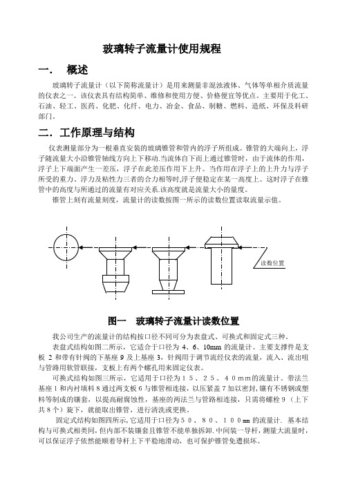
二.工作原理与结构仪表测量部分为一根垂直安装的玻璃锥管和管内的浮子所组成。
锥管的大端向上,浮子随流量大小沿锥管轴线方向上下移动.当流体自下而上通过锥管时,由于流体的作用,浮子上下端面产生一差压,浮子在此差压作用下上升。
当作用在浮子上的上升力与浮子所受的重力、浮力及粘性力三者的合力相等时,浮子便稳定在某一高度上。
这时浮子在锥管中的高度与所通过的流量有对应关系.该高度就是流量大小的量度。
锥管上刻有流量刻度,流量计的读数按图一所示的读数位置读取流量示值。
图一玻璃转子流量计读数位置我公司生产的流量计的结构按口径不同可分为表盘式、可换式和固定式三种。
表盘式结构如图二所示,它适合于口径为4、6、10mm的流量计。
主要支撑件是支板2和带有针阀的下基座9及上基座3,针阀用于调节流经仪表的流量,流入、流出咀与管路用软管联接,支板上有两个螺孔用来固定仪表。
可换式结构如图三所示,它适用于口径为15、25、40mm的流量计。
带法兰基座1和内衬填料8通过两支板6与锥管相连接,以压紧盖7加以密封,镶有不锈钢或塑料等制成的镶套,以提高耐腐蚀性,基座的两法兰与管路相连接,只需将螺栓9(上下共8个)旋下,就能取出锥管,进行清洗或更换。
固定式结构如图四所示,它适用于口径为50、80、100mm的流量计.•基本结构与可换式相类同,但内部不装镶套且锥管不能单独拆卸.中间装一导杆,测量大流量时,可以保证浮子依然能顺着导杆上下平稳地滑动,也可保护锥管免遭损坏。
三、基本参数及性能指标1、执行标准执行标准为ZBY138-83《玻璃转子流量计》。
2、使用环境条件(1)环境温度: —10~50℃;(2)相对温度:不超过95%;(3)流量计周围不应有强腐蚀气体。
上海安锐自动化仪表 LZ 系列 金属管浮子流量计 说明书
LZ系列金属管浮子流量计安装使用说明书(沪)制04000266号上海安锐自动化仪表有限公司 Shanghai AnRui Automatic Instrument Co.,Ltd目 录一、 产品概况 (3)二、 原理结构 (3)三、 技术要求 (3)四、 电性能 (4)五、限位开关报警装置 (4)六、型号规格 (5)七、 安装尺寸 (7)八、 使用与维修 (8)九、 仪表常见故障的维修 (9)十、 防爆产品使用注意事项 (10)十一、 设计选用及订货须知 (10)十二、附录 (11)LZ系列金属管浮子流量计安装使用说明书一、 产品概况LZ系列金属管浮子流量计结构简单、工作可靠、准确度高、适用范围广。
与玻璃转子流量计相比较能耐较高的压力。
LZ系列流量计具有就地指示、电远传、限位开关报警、耐腐蚀、夹套型、阻尼型和防爆等品种。
广泛应用于国防、化工、石油、冶金、电力、环保、医药和轻工等部门的液体、气体流量的测量与自动控制。
流量计检测部分零件均有1Cr18Ni9Ti不锈钢材料制成,特殊场合也可由0Cr18Ni12Mo2Ti或F46等耐腐蚀材料组成。
流量计除特殊规格外,高度均为250 mm。
连接法兰采用GB/T9119.8~10标准,也可根据用户特殊要求定制。
二、 原理结构由下而上的流体通过直立的测量管时,浮子在压差的作用下上升、浮子上升的高度即代表流量的大小。
并通过浮子中的磁钢与指示器中的磁钢耦合联结传递给指示器,带动指示器中的指针转动。
8 指示器7 弹簧卡圈6 浮子止挡5 管体4 测量体3 浮子2 浮子导向盘1 连接法兰图1仪表结构图三、 技术要求1.测量范围:水(2.5~6000)L/h;空气(0.07~2000)m3/h (在0.101025 MPa、20℃)。
2. 准确度等级: 1.5、2.5级。
3. 量程比: 10:1。
4. 工作压力: DN15~50,4 MPa ; DN80~100,1.6MPa 。
LUXZ型流量计说明书
LUXZ型智能旋进旋涡流量计1 概述LUXZ型智能旋进旋涡流量计(以下简称流量计)是本公司拥有自主产权的新一代智能一体化的流量测量仪表。
适用于石油、化工、钢铁、冶金、电力、轻工、环保及市政建设等行业中的天然气、煤气、压缩空气、氧气、二氧化碳及其它化工介质等流量的测量及控制。
流量计执行国家计量检定规程JJG198-94和Q/JY 1-2008企业标准。
2 特点集高精度压力传感器、温度传感器、流量传感器和智能流量积算单元为一体。
该流量计能直接测量和显示出被测介质的瞬时流量、累积流量、压力、温度等参数。
并对压力、温度、压缩因子进行自动跟踪补偿运算。
采用机电仪一体化技术,结构紧凑,无机械可动部件,稳定性好,寿命长;低流速特性好,对仪表的前后直管段要求低(前5D,后2D),操作方便,安装费用低;采用微功耗高新技术,既可由一节1#锂电池供电使用。
又可由外电源供电运行。
整机功耗低; LUXZ型智能旋进旋涡流量计采用高性能微处理器,软件功能强大,(对温度、压力)具有调零调量程功能,性能优越;2.6采用大屏幕液晶显示,可直接整版显示出工作状态下的瞬时流量、标准状态下的瞬时流量、累积流量、压力、温度等参数。
读数方便,清晰直观。
(见右图)具有实时数据储存功能,可防止换电池和突然掉电数据丢失。
在断电状态下,内部参数可永久性保持;采用双检测流量传感器,运用电路处理技术。
在提高测量精度与流量范围的同时,有效地抑制了因为管道振动对流量计带来的影响,使流量计计量更为准确可靠;防爆型式为:工厂用本质安全型;防爆标志为:ExibⅡBT5;防护等级为:IP54;3 主要技术性能指标基本参数3.1.1基本误差:气体级;电气性能指标:3.1.2 流量范围:(见表1) 3.3.1 工作电源:3.1.3 公称通径:(见表1) a) 内电源:由 DC.非充电锂电池组件供电。
3.1.4 工作压力:≦(铝合金); b) 外电源:+24V DC. (普通型)~(不锈钢304); +24V DC.由安全栅(具有防爆合格证) 供电;(防3.1.5 范围度:15∶1。
流量计说明书
流量计性能测定实验装置说明书天津大学化工学院化工基础实验中心2006年7月目录一、实验装置的功能及特点二、主要仪器仪表及技术参数三、实验装置流程四、实验方法及步骤五、操作时应注意的事项六、附录一、实验装置的功能及特点本实验装置具有如下功能:⑴ 了解各种流量计(节流式、转子、涡轮)的结构、使用方法和性能。
⑵ 了解流量计的标定方法。
⑶ 测定文丘里流量计的流量标定曲线(流量-压差关系)和流量系数和雷诺数之间的关系(Re 0 C 关系)。
实验设备的特点:⑴ 结构紧凑, 流程简单, 设备投资少。
⑵ 使用方便, 安全可靠, 节省实验时间。
⑶ 装置体积小, 重量轻, 移动方便。
二、主要仪器仪表及技术参数⑴ 离心泵: 型号 WB 70/055 转速n 2800 转/分 流量Q 20~120 L /min, 扬程H 19~13.5m⑵ 贮水槽: 550mm ×400mm ×450mm ⑶ 试验管路: 内径 26.0mm⑷ 涡轮流量计:φ25,最大流量 10m 3/h ,仪表常数830.54次/升 ⑸ 文丘里流量计:喉径φ15mm⑹ 转子流量计:LZB-25,量程0.25-2.5m 3/h ⑺ 铜电阻温度计;⑻ 差压变送器: 0-200kPa三、实验装置流程用离心泵3将贮水槽1的水直接送到实验管路中,经涡轮流量计计量后分别进入到转子流量计、文丘里流量计,最后返回贮水槽1。
用文丘里流量计测量时把阀门5打开,阀门6关闭;转子流量计测量时把阀门6打开,阀门5关闭。
流量由调节阀5、6来调节,温度由铜电阻温度计测量。
实验流程示意图见图1图1 流量计实验流程示意图1-水箱;2-放水阀;3-离心泵;4-排水阀;5-文丘里流量计调节阀;6-转子流量计调节阀;7-转子流量计;8-文丘里流量计;9-平衡阀;10-压力传感器;11-涡流流量计四、实验方法及步骤⒈关闭泵流量调节阀5、6,启动离心泵。
⒉测取文丘里流量计的性能,按流量从小到大的顺序进行实验。
LUX旋进旋涡流量计操作说明书
LUX旋进旋涡流量计使用说明目录一、概述二、结构与工作原理三、主要技术参数与功能四、选性与安装五、使用方法六、接线七、故障现象及排除方法八、包装、运输及贮存九、开箱及检查附录(一)天然气真实相对密度Gr的确定附录(二)天然气物理性质表智能旋进旋涡流量计一、概述智能旋进旋涡流量计是我公司开发研制的具有国内领先水平的新型气体流量仪表。
该流量计集流量、温度、压力检测功能于一体,并能进行温度、压力、压缩因子自动补偿,是石油、化工、电力、冶金等行业用于气体计量的理想仪表。
1.1产品主要特点●无机械可动部件,不易腐蚀,稳定可靠,寿命长,长期运行无须特殊维护;●采用16位电脑芯片,集成度高,体积小,性能好,整机功能强;●智能型流量计集流量探头、微处理器、压力、温度传感器于一体,采取内置式组合,使结构更加紧凑,可直接测量流体的流量、压力和温度,并自动实时跟踪补偿和压缩因子修正;●采用双检测技术可有效地提高检测信号强度,并抑制由管线振动引起的干扰;●采用国内领先的智能抗震技术,有效的抑制了震动和压力波动造成的干扰信号;●采用汉字点阵显示屏,显示位数多,读数直观方便,可直接显示工作状态下的体积流量、标准状态下的体积流量、总量,以及介质压力、温度等参数;●采用EEPROM技术,参数设置方便,可永久保存,并可保存最长达一年的历史数据;●显示仪可输出频率脉冲、4~20mA模拟信号,并具有RS485接口,可直接与微机联网,传输距离可达1.2km;●多物理量参数报警输出,可由用户任选其中之一;●流量计表头可360度旋转,安装使用简单方便;●配合本公司的FM型数据采集器,可通过因特网或者电话网络进行远程数据传输●压力、温度信号为传感器输入方式,互换性强;●整机功耗低,可用内电池供电,也可外接电源。
1.2主要用途智能旋进旋涡流量计可广泛应用于石油、化工、电力、冶金、城市供气等行业测量各种气体流量,是目前油田和城市天然气输配计量和贸易计量的首选产品。
- 1、下载文档前请自行甄别文档内容的完整性,平台不提供额外的编辑、内容补充、找答案等附加服务。
- 2、"仅部分预览"的文档,不可在线预览部分如存在完整性等问题,可反馈申请退款(可完整预览的文档不适用该条件!)。
- 3、如文档侵犯您的权益,请联系客服反馈,我们会尽快为您处理(人工客服工作时间:9:00-18:30)。
专利号:.2 渝制 00000645 号认证企业L U X Z 型一体化智能旋进旋涡流量计使用说明书LUXZ型智能旋进旋涡流量计1 概述LUXZ型智能旋进旋涡流量计(以下简称流量计)是本公司拥有自主产权的新一代智能一体化的流量测量仪表。
适用于石油、化工、钢铁、冶金、电力、轻工、环保及市政建设等行业中的天然气、煤气、压缩空气、氧气、二氧化碳及其它化工介质等流量的测量及控制。
流量计执行国家计量检定规程JJG198-94和Q/JY 1-2008企业标准。
2 特点集高精度压力传感器、温度传感器、流量传感器和智能流量积算单元为一体。
该流量计能直接测量和显示出被测介质的瞬时流量、累积流量、压力、温度等参数。
并对压力、温度、压缩因子进行自动跟踪补偿运算。
采用机电仪一体化技术,结构紧凑,无机械可动部件,稳定性好,寿命长;低流速特性好,对仪表的前后直管段要求低(前5D,后2D),操作方便,安装费用低;采用微功耗高新技术,既可由一节1#锂电池供电使用。
又可由外电源供电运行。
整机功耗低; LUXZ型智能旋进旋涡流量计采用高性能微处理器,软件功能强大,(对温度、压力)具有调零调量程功能,性能优越;2.6采用大屏幕液晶显示,可直接整版显示出工作状态下的瞬时流量、标准状态下的瞬时流量、累积流量、压力、温度等参数。
读数方便,清晰直观。
(见右图)具有实时数据储存功能,可防止换电池和突然掉电数据丢失。
在断电状态下,内部参数可永久性保持;采用双检测流量传感器,运用电路处理技术。
在提高测量精度与流量范围的同时,有效地抑制了因为管道振动对流量计带来的影响,使流量计计量更为准确可靠;防爆型式为:工厂用本质安全型;防爆标志为:ExibⅡBT5;防护等级为:IP54;3 主要技术性能指标基本参数T V P P T V P MA G NNN ⨯+=⨯)(3.1.1基本误差:气体级; 电气性能指标: 3.1.2 流量范围:(见表1) 3.3.1 工作电源:3.1.3 公称通径:(见表1) a) 内电源:由 DC.非充电锂电池组件供电。
3.1.4 工作压力:≦(铝合金); b) 外电源:+24V DC. (普通型)~(不锈钢304); +24V DC.由安全栅(具有防爆合格证) 供电;(防 3.1.5 范围度:15∶1。
爆型)3.1.6 被测介质:气体。
3.3.3 输出信号:(需外电源供电)3.1.7 介质温度:-20℃~+80℃。
a) 脉冲信号:标况或工况脉冲信号,TTL 电平。
3.1.8 环境温度:-30℃~+70℃。
b) 模拟信号:4mA ~20mA . (可选) 3.1.9 相对湿度:5%~95%。
c) RS —485通讯:可直接与上位机或本公司的 3.1.9 相对湿度:5%~95%。
XLZ 智能流量积算仪联网。
远传被测介质的温度、 大气压力:86kPa ~106kPa 。
压力、流量等多种信号,传输距离≤1500m 。
(可选) 1LUXZ型智能旋进旋涡流量计表1 公称通径和流量范围注:上表中的气体流量值是工作状态下的体积流量,在选表时,往往已知的是标准状态下的流量,这时应 把它换算成工作状态下的体积流量。
实际气体状态方程为:(1)根据实际气体状态方程,把标准状态下的流量换算成工作状态下的体积流量,换算公式见(2)式。
(P G+P A)T N Z NV N = ·— V m (2)P N T Z式中:V N—标准状态下的体积流量(Nm3); V m—工作状态下的体积流量(m3);P G—工作状态下管线压力(表压力kPa); P A—当地大气压(kPa);P N—标准大气压(); T N—标准状态下的绝对温度[(+20)K];T —被测介质的绝对温度[(+t)K]; Z —工作状态下的压缩系数;Z N—标准状态下的压缩系数;4 工作原理及结构工作原理a)智能旋进旋涡流量计工作原理流入流量计的流体通过起旋体使其剧烈的旋转形成旋涡流,接着在文丘利管中旋进,到达节流段使旋涡流加速。
当旋涡流进入扩散段后,旋涡流被减速,因而压力上升,导致旋涡流发生进动。
由于进动运动,旋涡流偏心地旋转,所以流体在管道截面切线方向的速度分量按进动频率周期性地变动。
实验证明,进动运动的频率与流速成正比,因此只要用传感器检测出进动频率,经放大器放大整形处理,转换成频率与流量成正比的脉冲信号,并与温度传感器、压力传感器检测到的信号一起送入智能流量积算单元进行运算处理。
b)流量积算单元工作原理由温度和压力传感器以及微处理单元组成,并配有外输入信号接口,输出各种信号。
流量计中的微处理单元按照气态方程进行温压补偿,并自动进行压缩因子修正。
流量计结构由旋进旋涡流量传感器、流量积算单元、压力传感器及温度传感器四大部分组成。
2LUXZ型智能旋进旋涡流量计5 流量计外形尺寸及安装外形尺寸流量计外形尺寸见图1及表2、表3所示。
安装流量计采用法兰安装,法兰尺寸符合GB 81—1988的规定。
安装方法见图2所示。
图1 流量计外形尺寸图2 流量计安装示意图表2 流量计外形尺寸(铝合金)单位:mm 通径D N A D K N L H 2014511585414380 2514511585414380 32168140100418385 40190150110418400 50233175135823415 65262185145823445 80332200160818455 100410220180818470 125500250210818500 150580285240822530 2007003402951223570表3 流量计外形尺寸(不锈钢)单位:mm 通径D N A D K N L H 2018011585414380 2518011585414380 32200140100418385 40200150110418400 50233175135823415 65262185145823445流量计可以水平、垂直或倾斜安装在被测管道上。
但被测介质为液体时,流体宜从下向上。
被测管道内径应与流量计的内径一致, 管道两端法兰焊接应保持平行,且两端密封垫不得突入表体孔内。
管道开间不得大于表体长度3毫米,以免将表体法兰拉裂或拉断。
3LUXZ型智能旋进旋涡流量计不管那种安装,都要求流体充满管道,且流量计的上游直管段长度≥5D,下游直管段长度≥2D。
为了便于维修,不影响被测介质的正常输送,最好设置旁通管道。
流量计安装在室外时,其上部有遮盖物,以避免雨水侵入或烈日曝晒而影响流量计的使用寿命。
流量计周围不能有强烈的机械振动或强磁场。
流量计必须可靠接地,不得与强电系统共用地线,接地电阻应不大于10Ω。
对于防爆型流量计的安装应符合GB 、GB 有关要求,维修时应遵守有关安全规程进行操作。
使用过程中,不得自行更改防爆系统的连接方式或任意拧动各个引线接口螺钉。
6 使用流量计选型用户应根据管道输气量及介质可能达到的温度和压力范围,用(2)式把已知的标准状态下的体积流量换算成工作状态下的体积流量,再对照表1给出的不同口径流量计的流量范围,正确选择合适的流量计。
当两种口径流量计均能覆盖最低和最高体积流量时,在压损允许下,应尽量选小口径。
显示方式正常工作状态和指示状态显示方式(见表4)设定参数显示方式各设定参数通过操作按键显示于液晶屏上,其定义、符号和显示方式(见表5)。
参数的设定为了防止恶意改变仪表参数,影响计量精度,本仪表特设置密码功能,在修改或设定各参数时,必须事先对仪表密码进行确认,经正确确认后,才能对各参数进行修改或设定。
当允许对某参数的位进行修改或设定时,则该位数字闪烁显示以示区别。
表4 表头正常工作状态和指示状态显示方式表5 参数显示及参数设置4LUXZ型智能旋进旋涡流量计注意!各参数在仪表出厂时均已设定妥当(除需由用户设定的参数外),不允许任意改注意!各参数在仪表出厂时均已设定妥当(除需由用户设定的参数外),不允许任意改动,以免影响仪表计量精度或正常工作。
密码的确认按复位键(Reset)使液晶显示P 000字样,顺按移位键(< >)和数字键(+1),从右至左逐位把数值设定与原密码相同,然后按确认键(Enter)进行确认。
如密码正确,则进入参数设置状态,否则自动返回初始工作状态。
参数的设定密码经正确确认后,则可对各项参数进行修改或设定,按确认键(Enter)至被修改或设定的参数状态,顺按移位键( < > )和数字键( + 1 )从右至左进行逐位设定,数值设定正确后再按确认键(Enter)进行确认。
各参数设定完毕后仪表自动返回初始工作状态。
接线方法流量积算仪外接线功能如下:(见积算仪后面)红线:电源正,V+;黑线:电源地,V-。
蓝线:频率输出,f;或标准电流信号输出I(4~20mA);如选RS-485通讯:黄线:A:同相接收器输入和同相驱动器输出;绿线:B;反相接收器输入和反相驱动器输出;仪表接线:(见积算仪后面)电平方波脉冲;标准电流信号输出;电源 +(脉冲输出时用);通讯信号;RS-485通讯信号;电源 -;(两线制:电源负作信号输出端)电源 +;(电流信号输出时用)注意!内部各传感器引线在仪表出厂时均已接好,请勿随意更改。
内置电池的更换方法打开积算仪后盖,取出旧电池,按护盖上的极性标志装上新电池(1节1#锂电池),然后装上积算仪后盖即可。
注意!该流量计所用电池为非充电锂电池,严禁随意拆卸和对它进行充电!7 包装、运输及储存流量计的包装应符合GB/T15464—1995规定,搬运时小心轻放,不允许野蛮装卸。
存放地点应符合以下条件:a) 防雨防潮及不受机械振动或冲击;b) 温度范围:-10℃~+45℃;c) 相对湿度:不大于80%;d) 空气中不含对流量计起腐蚀作用的有害物质。
5LUXZ型智能旋进旋涡流量计8 开箱及检查开箱时应检查外部包装的完整性,根据装箱单核对箱内物品数量、规格,检查仪表及附件的完好性。
随机文件:a)使用说明书(1本);b)产品合格证书(1份);c)产品检定证书(1份);9 常见故障及排除方法(见表6)表6常见故障及排除方法6单位:重庆嘉渝仪表有限公司地址:重庆市北碚区同兴工业园区盈田工谷5-4号电话:(023)传真:(023)邮编:400700Http:。