瑞萨单片机启动文件介绍
瑞萨H8_3048单片机资源

16位集成定时器H8_3048系类单片机内还有一个16位的集成定时单元ITU,有五个16位定时通道0到4。
1.结构与特点1.1内部结构每个通道还有三个16为寄存器:定时计数器TCNT,通用寄存器GRA 和GRB;四个8为寄存器:定时控制寄存器TCR,定时I/O控制寄存器TIOR,定时中断允许寄存器TIER和定时状态寄存器TSR.ITU有TCLKA到TCLKD等四个外部时钟输入,以及四种频率的内部时钟输入。
可以从这八个时钟源中选定一个座位通道定时计数器TCNT 的计数源。
TCNT可以产生计数溢出中断,与通用寄存器GRA或GRB 比较中断,捕捉到有效信号时TCNT 值传给GRA或GRB,也可同时请求IMIA或IMIB中断。
通道3和通道4还多了两个寄存器BRA和BRB,它们是16位的缓冲寄存器。
通道4还多了两条输出比较引脚——TOCXA4和TOCXB4.1.2 ITU的特点1)可以处理多达12个脉冲输出或10个脉冲输入;2)10个通用寄存器可单独赋予输出比较或输入捕获功能;3)每个通道均可从8个时钟源中任选一个;4)5个通道中,对每个都有5种运作方式可供选择。
1.3 输入输出引脚(这里只说明工作在PWM方式下)通道0到通道2都有两个输入/输出引脚通道0 TIOCA0 GRA0输出比较或输入捕捉引脚,PWM方式下的PWM输出引脚TIOCB0 GRB0输出比较或输入捕捉引脚;通道1和通道2和通道0一样,这里就不在作详解。
通道3和通道4在联合使用输出互补或复位同步PWM是有六个引脚都可以作为PWM的输出引脚。
1.4 寄存器配置2 寄存器功能2.1 定时器启动寄存器TSTR(八位寄存器)5,6,7位恒为1;4至0为依次为五个通道计数器开启停止的控制位置1开启,置0停止。
2.2 定时器同步寄存器TSNC(八位寄存器)5,6,7位恒为1,;4到0为依次为对应的计数器的独立运作还是同步运作控制位,置0则为独立运作,置1则为同步运作。
MCU灵活软件包启动文件说明

现在很多M C U都配套有软件包,不再像以前那样从零(汇编、寄存器)开始了。
而本文给大家描述的瑞萨M C U也是通过灵活软件包(F S P)进行快速初始化外设,下面就给大家讲讲F S P灵活软件包那些重要的内容。
F S P介绍FSP:F l e x i b l e S o f t w a r e P a c k a g e,即瑞萨M C U的软件包,类似于K e i l M D K中需要安装的软件包(K e i l.S T M32F1x x_D F P.2.4.0.p a c k)。
瑞萨灵活软件包(F S P)是一个灵活配置的软件包,旨在提供易于使用、可扩展、高质量的嵌入式系统设计软件。
它适用于R A系列的M C U,提供了统一直观的A P I,并有详细的解释和例程应用,可以按照客户不同的需求自动生成相应驱动程序。
启动文件说明启动文件是程序上电复位后执行的第一个程序。
它一般包括如下几个:1.初始化堆栈2.使能FPU3.定位中断向量表4.配置系统时钟5.启用CORTEX-M33栈监视器6.初始化C语言运行环境7.初始化变量SystemCoreClock,这个变量存放的是处理器时钟的频率8.初始化用于触发NVIC中断的ELC(事件链接控制)9.BSP初始化初始化堆栈D三初始化堆栈1、栈区(S t a c k)一种顺序数据结构,满足后进先出原则。
由编译器自动分配释放,存放函数的参数值,局部变量的值等。
栈特别方便用来保存/恢复调用现场。
在函数被调用时,其参数也会被压入发起调用的进程栈中,并待到调用结束后,函数的返回值也会被存放回栈中。
如果函数调用时,如果函数参数和局部变量较多,寄存器放不下,则需要适当增加栈区的大小。
2、堆区(h e a p)通常由程序员手动分配,使用m a l l o c和f r e e进行分配和释放。
注意,使用完需及时释放(f r e e),否则容易造成内存泄漏。
3、e2S t u d i o中堆栈的设置宏“B S P_C F G_S T A C K_M A I N_B Y T E S”可以在F S P C o n f i g u r a t i o n的“B S P”属性栏中的“RA C o m m o n”中通过修改“M a i n s t a c k s i z e”设置,默认为1K B(0x400B y t e)。
瑞萨用户手册附加文档
3. You should not alter, modify, copy, or otherwise misappropriate any Renesas Electronics product, whether in whole or in part.
瑞萨E8a使用手册(中文)

8. You should use the Renesas Electronics products described in this document within the range specified by Renesas Electronics, especially with respect to the maximum rating, operating supply voltage range, movement power voltage range, heat radiation characteristics, installation and other product characteristics. Renesas Electronics shall have no liability for malfunctions or damages arising out of the use of Renesas Electronics products beyond such specified ranges.
R5F100LEA瑞萨 MCU官方资料(2)

1. InstallationDo not connect the E1 debugger module until the software support has been installed.1.Insert the CD into your computer’s CD-ROM drive. The CD should automatically run the installation program.If the installer does not start, browse to the CD root folder and double click on ‘CsPlusLauncher.exe’.2.Windows™ Vista/Windows™ 7 users may see “User Account Control” dialog box. If applicable, enter theadministrator password and click <OK>.3.The pre installer will first check to see if the CubeSuite prerequisites are present, and will install if necessary(this may take a few minutes).4.Once the prerequisites are setup, the CubeSuite+ installer will launch.5.The CubeSuite+ Welcome window will appear. Click <Next>.6.The End User License Agreement appears. Read the license agreement and select <Accept> if you wish tocontinue. Click <Next>.7.The ‘Select Component’ window appears. Review the components by selecting each component in turn.Click <Next> to continue.8.The License Key Registration window appears. If you have a license key available, click the <LicenseManager> button, otherwise go to Step 9. Enter the license key in the opened ‘License Manager’ dialog. Add the license key. Click <Add>. If the license key is added successfully, click <Close>.9.Click <Next>.10.The ‘Installation Settings Confirmation’ window appears. Review the information and click <Next> to begininstallation.11.The ‘Installation Execution’ window will appear showing the install status progress. Before completion, theRenesas E-Series USB Driver installation dialog will appear. Windows™ Vista and Windows™ 7 users may see a ‘Windows Security’ dialog box. Click ‘Always trust software from “Renesas Solutions Corp.”’ then click <Install>. 12.After a successful installation click <Next>.13.The ‘Setup Completion’ window will appear. Click <Finish> to close the installer.2. Connection14.Fit the LCD module to the connector marked ‘LCD’ on the RSK. Ensure all the pins of the connector arecorrectly inserted in the socket.15.Connect the E1 debugger module to the connector marked ‘E1’ on the RSK using the ribbon cable.16.Connect the E1 debugger module to a spare USB port of your PC. The green ‘ACT’ LED on the E1 debuggerwill flash.17.The ‘Found New Hardware’ Wizard will appear. Please follow the steps below to install the drivers. Note that,administrator privileges are required for a Windows™ XP/Vista machine.Windows™ XP Windows™ Vista / Windows™ 7a.Select option ‘No, not this time’ in “Found NewHardware” Wizard dialog, and click <Next>button.a.“Device driver software installed successfully”pop-up will appear in the Windows toolbar andinstallation will complete.b.Verify the “Recommended” option is selectedand click <Next>.c.If using Windows™ XP, go to step ‘e’;otherwise, click <Next>.d.Click <Next> to install the driver.e.Click <Finish> to close the wizard.Note: The Windows driver signing dialog may be displayed. Please accept the driver to continue.18.The green ‘ACT’ LED on the E1 debugger will illuminate.3. CubeSuite+ ProjectCubeSuite+ integrates various tools such as compiler, assembler, debugger and editor into a common graphical user interface. To learn more on how to use CubeSuite+, refer to the CubeSuite+ Tutorial manual from the menu bar (Help > Tutorial).unch CubeSuite+ from the Windows Start Menu. (Start Menu > All Programs > Renesas ElectronicsCubeSuite+ > CubeSuite+).20.The ‘One Point Advice’ dialog which provides useful tips will open. The detail for this is out of scope for thisguide. Click <OK>.21.The Start panel will appear. Select the RSKRL78G13_Tutorial project under the “Open Sample RSK Project”and click <GO>.22.In the “Create Project” dialog that follows, specify a name for the project. Leave the list of subprojectsunselected.23.Click “Create” to launch the main Tutorial project.4. Programming and Debug24. Click on RL78 Simulator (Debug Tool) from the Project Tree pane and select the “RL78 E1 (Serial)” asshown in the following screenshot:25. Right-click on “RL78 E1(Serial) (Debug Tool)” and select ‘Property’.26. On the ‘Property’ tab, select “Power target from the emulator.(MAX200mA)”.27. Click on the drop-down menu button on the right and select “Yes”. A new entry, “Supply voltage”, will appear. 28.Click on the “Supply voltage” entry and change the voltage to 5.0V from the drop-down menu.29.Build the project by clicking on the Build Project button.30.Download the code to the microcontroller by clicking on the download buttonor click on Debug from the Menu bar and click on Download as shown below:31.Click the <Restart> button to reset the CPU then start program execution.The user LEDs on the board will flash at regular intervals. Pressing any of the switches on the RSK, or after 200 flashes have elapsed, will display the string STATIC on the second line of the debug LCD. The second line will then be replaced with the string TESTTEST one character at a time; whilst allowing you to control the user LEDs’ flashing rate using the potentiometer shaft. 32.Click the <Stop> button.The code will stop and the source code will be opened at the current program counter.5. Next StepAfter you have completed this quick start procedure, please review the tutorial code and sample code that came with the kit. You can review these codes by changing the active project to another project. The tutorials will help you understand the device and development process using Renesas Development Tools.The Hardware manual supplied with this RSK is current at the time of publication. Please check for any updates to the device manual from the Renesas internet site at: /rskrl78g136. Renesas RL78 CompilerThe version of the compiler provided with this RSK is fully functional with no time restrictions. The compiler will limit the code linker to 64k bytes. Full licensed RL78 compiler versions are available from your Renesas supplier.7. User ManualsUser manuals can found in the Windows Start Menu. (Start Menu > All Programs > Renesas ElectronicsCubeSuite+ > Readme Documents > RSK > RSKRL78G13).8. SupportOnline technical support and information is available at: /rskrl78g13 Technical Contact Details csc@Note on Update Manager : The Update Manager checks via Internet for any updated resources available for each installed CubeSuite+ tool and downloads them accordingly to simplify the update process. Automatic updates will not work if CubeSuite+ is installed without a license key.© 2011 Renesas Electronics Europe Limited. All rights reserved. © 2011 Renesas Electronics Corporation. All rights reserved. © 2011 Renesas Solutions Corp. All rights reserved. Website: D010234_11_S01_V01。
瑞萨单片机入门教程
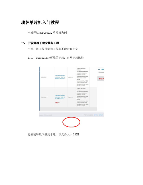
瑞萨单片机入门教程本教程以R7F0C002L单片机为例一、开发环境下载安装与工程注意:该工程目录和工程名不能含有中文1.1、 CubeSuite+环境的下载:官网下载地址将安装环境下载到本地,该文件大小532M在安装过程中有提示需要填写注册码,请输入以下注册码,如果无效请联系供应商。
查看是否已经注册:在IDE环境中选择 Help->About后有下面窗口:注册码:67DCS-V3Q7L-XMGL9-FI6L9-EE1BJ该注册码有限制台数的,一旦注册了就会把MAC绑定,重装无需注册!当有以下报错时:请查看是否已经注册。
1.2、按照一般的软件安装方法安装好IDE环境,下面介绍IDE环境的配置:1、将DIF_RFP文件夹下的Device_Custom文件夹拷贝到安装目录下的C:\Program Files\Renesas Electronics\CubeSuite+下(这里是默认的安装目录,另外注意:DIF_RFP中Readme_Device_Custom.txt说将Device_Custom文件夹拷贝到C:\Program Files\Renesas Electronics\CubeSuite+\Device下,但是实际上不可以!)。
DIF_RFP文件夹安装根目录当配置成功以后会在芯片族里面多出R7F系列的单片机,如下图示:2、将DIF_RFP文件夹下的RFP_R7F0C002L_V10000子目录下面的两个文件(Device_Custom文件夹和Custom_Productlist.xml文件)拷贝到安装目录下的C:\Program Files\Renesas Electronics\Programming Tools\Renesas Flash Programmer V2.01\Device下(这里是默认安装路径)。
1.3、开发环境新建工程:1、启动CubeSuite+环境,会弹出如下启动界面:2、创建Project工程,在上述启动界面中,点击Creat New Project栏中GO按钮,将会弹出以下对话框:选择工程路径创建输入工程名选择芯片型号选择芯片族3、点击Create创建工程,会得到如下工程界面:4、通过生成工具生成一个简单的代码:5、将芯片型号换成R7F0C002单片机,并且将选项字节配置好!详细设置请参考第三章代码生成与编码。
瑞萨单片机在线升级操作说明

瑞萨单片机在线升级操作说明说明:共有两个程序代码,上电复位运行Bootload程序,然后检查EEPROM里面是否置位,如果置位,则需要进行APP代码更新,否则运行已有的APP代码。
一、使用瑞萨单片机R5F2L357C为例该单片机ROM资源如下,1、块A-D为数据闪存,未用。
2、默认ROM空间起始地址为0x4000h3、中断向量分为固定向量和可变向量,默认地址分别为:固定向量Fvector:0xFFD8-0xFFFF可变向量vector:0xFED8(至偏移256字节处)工程文件中可查:在fvector.c文件中#pragma sectaddress fvector,ROMDATA 0xFFD8我们要修改的两个程序代码空间分配为1、APP 用户程序代码编译出来有35.4K的空间,存放在块2、块3和块4,共40K的空间,地址为04000h-0DFFFh2、Bootload程序代码编译出来有5.2K的空间,存放在块0和块1,共8K的空间,地址为0E000h-0FFFFh。
二、Bootload程序代码制作1、修改ROM空间的起始地址,默认为0x4000,改为0xE000,如下所示。
编译完成后,可直接烧录该文件。
三、APP用户代码制作(I_Collector_Update)1、修改APP用户代码的固定向量和可变向量地址:将vector地址由0xFED8改为0x0DED8在fvector.c文件中#pragma sectaddress fvector,ROMDATA 0xffd8改为#pragma sectaddress fvector,ROMDATA 0xdfd8重新编译下,可以看出,地址不超出0x0e000,在块2范围内将编译的mot文件用FDT4.09工具打开另存为.bin文件,用UltraEdit打开.bin文件,将0x4000-0xe000地址以外的数据删除,保存。
此文件为在线烧录更新的文件。
这个文件可以用电脑串口发给单片机,单片机接收后IAP,自动运行。
1-瑞萨启动代码简介

声明:本文以瑞萨R8CTiny系列的单片机R5F2L368CDFP为例(R8C/L36C群)第一步:新建工程新建一个汇编项目Project Type 为Application类型。
自动生成如下源代码文件:nc_define.inc --------------------------------------------------------配置堆栈sect30.inc --------------------------------------------------------内存分配ncrt0.a30 -------------------------------------------------------启动代码sfr_r8l36c.h ------------------------------CPU相关SFR寄存器FOR Csfr_r8l36c.inc ------------------------------CPU相关SFR寄存器FOR ASM下面着重分析前三个文件:nc_define.inc 英文注释已经很清楚了。
__STANDARD_IO__ .equ0; STANDARD I/O flag definition__HEAPSIZE__ .equ080H; HEEP SIZE definition__STACKSIZE__ .equ080H; STACK SIZE definition__ISTACKSIZE__ .equ080H; INTERRUPT STACK SIZE definition__VECTOR_ADR__ .equ0fed8H; INTERRUPT VECTOR ADDRESS definition __ROM_TOPADR__ .equ04000H; ROM TOP ADDRESS definitionsect30.inc (已经去除部分注释)本文件的主要功能是各种段地址的定义,固定中断向量定义,可变中断向量的定义。
- 1、下载文档前请自行甄别文档内容的完整性,平台不提供额外的编辑、内容补充、找答案等附加服务。
- 2、"仅部分预览"的文档,不可在线预览部分如存在完整性等问题,可反馈申请退款(可完整预览的文档不适用该条件!)。
- 3、如文档侵犯您的权益,请联系客服反馈,我们会尽快为您处理(人工客服工作时间:9:00-18:30)。
瑞萨单片机启动文件介绍1.NC30介绍NC30的组件:nc30----------------编译驱动器cpp30---------------预处理器ccom30--------------编译器aopt30--------------汇编优化器sbauto--------------SB寄存器自动更新工具stkviewer & stk-----STK查看器与堆栈大小计算工具utl30---------------SBDATA声明及SPECIAL页函数声明工具mapview-------------映射查看器看下NC30处理流程:程序开发流程,生成X30文件的流程:以上就是编译器所做的工作和流程。
看了之后大家有了大概的了解。
具体的大家可以参看NC30编译器手册,待会会上传附件给大家下载。
2:启动程序介绍ncrt0.a30这个程序在程序启动或复位后立即运行,它主要执行下列处理:.设置SBDATA区.设置处理器的操作模式.初始化堆栈指针.初始化SB寄存器.初始化INTB寄存器.初始化NEAR数据区.初始化FAR数据区.初始化堆区.初始化标准I/O函数程序库.初始化FB寄存器.调用MAIN函数ncrt0.a30汇编文件,在建立工程的时候会自动生成。
以下附带详细注释,附件也可下载。
;***************************************************************************; C Compiler for R8C/Tiny, M16C/60,30,20,10; Copyright(C) 1999(2000-2006). Renesas Technology Corp.; and Renesas Solutions Corp., All rights reserved.;; ncrt0.a30 : Startup Program for M16C family;; $Date: 2006/11/22 04:13:23 $; $Revision: 1.1.4.1 $;***************************************************************************;---------------------------------------------------------------------; include files ;包含文件;---------------------------------------------------------------------.list OFF ;控制行输出数据输出到列表文件OFF:停止ON:开始.include nc_define.inc ;包含宏文件.include sect30.inc ;包含存储器映射文件.list ON;---------------------------------------------------------------------; BankSelect definition for 4M mode;---------------------------------------------------------------------; .glb __BankSelect;__BankSelect .equ 0BH;===================================================================== ; Interrupt section start ;中断段起始;---------------------------------------------------------------------.insf start,S,0.glb start.section interruptstart: ;复位后从这个标签开始运行;---------------------------------------------------------------------; after reset,this program will start ;复位后程序将启动;---------------------------------------------------------------------ldc #istack_top,isp ;设置istack指针(中断堆栈) ldc向专用寄存器ISP传递数据mov.b #02h,0ah ;保护寄存器PRCR PRC1=1 允许写PM0mov.b #00h,04h ;设置处理器模式PM0mov.b #00h,0ah ;关闭写保护.if __STACKSIZE__ != 0ldc #0080h,flg ;设置FLG寄存器IPL和其他状态FLG是16位标志寄存器堆栈指针选择USPldc #stack_top,sp ;设置堆栈指针.elseldc #0000h,flg.endifldc #data_SE_top,sb ;设置SB静态基址寄存器ldintb #__VECTOR_ADR__ ;向INTB寄存器传送指令,所以这里省了目标操作数intb;=====================================================================; NEAR area initialize. ;NEAR区初始化;---------------------- -----------------------------------------------; bss zero clear ;bss零清除;---------------------------------------------------------------------N_BZERO bss_SE_top,bss_SE ;清除NEAR bss段至零N_BZERO bss_SO_top,bss_SO ;N_BZERO清零宏定义N_BZERO bss_NE_top,bss_NE ;sect30.inc中有定义N_BZERO bss_NO_top,bss_NO;---------------------------------------------------------------------; initialize data section ;初始化数据段;---------------------------------------------------------------------N_BCOPY data_SEI_top,data_SE_top,data_SE ;将NEAR数据段和SBDA TA数据段的初始值转移到RAMN_BCOPY data_SOI_top,data_SO_top,data_SO ;N_BCOPY拷贝宏定义N_BCOPY data_NEI_top,data_NE_top,data_NE ;sect30.inc中有定义N_BCOPY data_NOI_top,data_NO_top,data_NO;=====================================================================; FAR area initialize. ;FAR区初始化;---------------------------------------------------------------------; bss zero clear ;bss零清除;---------------------------------------------------------------------.if __FAR_RAM_FLG__ != 0BZERO bss_FE_top,bss_FEBZERO bss_FO_top,bss_FO.endif;---------------------------------------------------------------------; initialize data section ;将FAR段数据段的初始值移到RAM中;---------------------------------------------------------------------.if __FAR_RAM_FLG__ != 0 ;从edata_EI(OI)段复制edata_E(O)段BCOPY data_FEI_top,data_FE_top,data_FEBCOPY data_FOI_top,data_FO_top,data_FOldc #stack_top,sp.stk -40.endif;===================================================================== ; heap area initialize ;堆区初始化;---------------------------------------------------------------------.if __HEAPSIZE__ != 0.glb __mnext.glb __msizemov.w #(heap_top&0FFFFH),__mnextmov.w #(heap_top>>16),__mnext+2mov.w #(__HEAPSIZE__&0FFFFH),__msizemov.w #(__HEAPSIZE__>>16),__msize+2.endif;===================================================================== ; Initialize standard I/O ;初始化标准I/O;---------------------------------------------------------------------.if __STANDARD_IO__ == 1.glb __init.call __init,Gjsr.a __init.endif;===================================================================== ; Call main() function ;调用MAIN函数;---------------------------------------------------------------------ldc #0h,fb ; for debuger 用于调试器.glb _mainjsr.a _main;===================================================================== ; exit() function ;推出函数;---------------------------------------------------------------------.glb _exit.glb $exit_exit: ; End program 结束程序$exit:jmp _exit.einsf;===================================================================== ; dummy interrupt function ;虚设的中断处理函数;---------------------------------------------------------------------.glb dummy_intdummy_int:reit.end;***************************************************************************; C Compiler for R8C/Tiny, M16C/60,30,20,10; Copyright(C) 1999(2000-2006). Renesas Technology Corp.; and Renesas Solutions Corp., All rights reserved.;***************************************************************************映射文件:sect30.inc.映射各个段.设置段的起始地址.定义堆栈和堆段的大小.设置中断向量表.设置固定向量表.宏定义;***************************************************************************; C Compiler for R8C/Tiny, M16C/60,30,20,10; Copyright(C) 1999(2000-2006). Renesas Technology Corp.; and Renesas Solutions Corp., All rights reserved.;; sect30.inc : section definition for M16C family;; $Date: 2007/01/09 04:38:46 $; $Revision: 1.1.4.1 $;***************************************************************************;===================================================================== ;; Arrangement of section ;段的排列;;---------------------------------------------------------------------; Near RAM data area ;Near RAM数据区;---------------------------------------------------------------------; SBDATA area.section data_SE,DATA.org 400Hdata_SE_top:.section bss_SE,DATA,ALIGNbss_SE_top:.section data_SO,DATAdata_SO_top:.section bss_SO,DATAbss_SO_top:; SBDATA area definition.glb __SB____SB__ .equ data_SE_top; near RAM area.section data_NE,DATA,ALIGNdata_NE_top:.section bss_NE,DATA,ALIGNbss_NE_top:.section data_NO,DATAdata_NO_top:.section bss_NO,DATAbss_NO_top:;--------------------------------------------------------------------- ; Stack area ;堆栈区;--------------------------------------------------------------------- .section stack,DATA,ALIGN.blkb __ISTACKSIZE__ ;.blkb分配一字节ram istack_top:.if __STACKSIZE__ != 0.blkb __STACKSIZE__stack_top:.endif;--------------------------------------------------------------------- ; heap section ;heap段;--------------------------------------------------------------------- .if __HEAPSIZE__ != 0.section heap,DATAheap_top:.blkb __HEAPSIZE__.endif;--------------------------------------------------------------------- ; Near ROM data area ;NEAR rom数据区;--------------------------------------------------------------------- .if __NEAR_ROM_FLG__ != 0.section rom_NE,ROMDATA,ALIGNrom_NE_top:.section rom_NO,ROMDATArom_NO_top:.endif;--------------------------------------------------------------------- ; Far RAM data area ;FAR RAM 数据区;--------------------------------------------------------------------- .if __FAR_RAM_FLG__ != 0.section data_FE,DATA.org 10000Hdata_FE_top:.section bss_FE,DATA,ALIGNbss_FE_top:.section data_FO,DATAdata_FO_top:.section bss_FO,DATAbss_FO_top:.endif;--------------------------------------------------------------------- ; Far ROM data area ;FAR ROM 数据;--------------------------------------------------------------------- .section rom_FE,ROMDATA.org __ROM_TOPADR__rom_FE_top:.section rom_FO,ROMDATArom_FO_top:;--------------------------------------------------------------------- ; Initial data of 'data' section ;far rom数据初始化;--------------------------------------------------------------------- .section data_SEI,ROMDATA,ALIGNdata_SEI_top:.section data_SOI,ROMDATAdata_SOI_top:.section data_NEI,ROMDATA,ALIGNdata_NEI_top:.section data_NOI,ROMDATAdata_NOI_top:.if __FAR_RAM_FLG__ != 0.section data_FEI,ROMDATA,ALIGNdata_FEI_top:.section data_FOI,ROMDATAdata_FOI_top:.endif;--------------------------------------------------------------------- ; Switch Table Section;--------------------------------------------------------------------- ; .section switch_table,ROMDATA;switch_table_top:;--------------------------------------------------------------------- ; code area ;代码区;--------------------------------------------------------------------- .section program,CODE,ALIGN.section interrupt,CODE,ALIGN.section program_S,CODE,ALIGN;---------------------------------------------------------------------; variable vector section ;变量向量段;---------------------------------------------------------------------.section vector,ROMDATA.org __VECTOR_ADR__.if 0.lword dummy_int ; vector 0 BRK.lword dummy_int ; vector 1.lword dummy_int ; vector 2.lword dummy_int ; vector 3.lword dummy_int ; vector 4 (for user) int3.lword dummy_int ; vector 5 (for user) timerB5.lword dummy_int ; vector 6 (for user) timerB4.lword dummy_int ; vector 7 (for user) timerB3.lword dummy_int ; vector 8 (for user) si/o4/int5.lword dummy_int ; vector 9 (for user) si/o3/int4.lword dummy_int ; vector 10 (for user) Bus collision detection .lword dummy_int ; vector 11 (for user) DMA0.lword dummy_int ; vector 12 (for user) DMA1.lword dummy_int ; vector 13 (for user) Key input interrupt.lword dummy_int ; vector 14 (for user) A-D.lword dummy_int ; vector 15 (for user) uart2 transmit.lword dummy_int ; vector 16 (for user) uart2 receive.lword dummy_int ; vector 17 (for user) uart0 transmit.lword dummy_int ; vector 18 (for user) uart0 receive.lword dummy_int ; vector 19 (for user) uart1 transmit.lword dummy_int ; vector 20 (for user) uart1 receive.lword dummy_int ; vector 21 (for user) timer A0.lword dummy_int ; vector 22 (for user) timer A1.lword dummy_int ; vector 23 (for user) timer A2.lword dummy_int ; vector 24 (for user) timer A3.lword dummy_int ; vector 25 (for user) timer A4.lword dummy_int ; vector 26 (for user) timer B0.lword dummy_int ; vector 27 (for user) timer B1.lword dummy_int ; vector 28 (for user) timer B2.lword dummy_int ; vector 29 (for user) int0.lword dummy_int ; vector 30 (for user) int1.lword dummy_int ; vector 31 (for user) int2.lword dummy_int ; vector 32 (for user or MR30).lword dummy_int ; vector 33 (for user or MR30).lword dummy_int ; vector 34 (for user or MR30).lword dummy_int ; vector 35 (for user or MR30).lword dummy_int ; vector 36 (for user or MR30).lword dummy_int ; vector 37 (for user or MR30).lword dummy_int ; vector 38 (for user or MR30).lword dummy_int ; vector 39 (for user or MR30).lword dummy_int ; vector 40 (for user or MR30).lword dummy_int ; vector 41 (for user or MR30).lword dummy_int ; vector 42 (for user or MR30).lword dummy_int ; vector 43 (for user or MR30).lword dummy_int ; vector 44 (for user or MR30).lword dummy_int ; vector 45 (for user or MR30).lword dummy_int ; vector 46 (for user or MR30).lword dummy_int ; vector 47 (for user or MR30) .lword dummy_int ; vector 48.lword dummy_int ; vector 49.lword dummy_int ; vector 50.lword dummy_int ; vector 51.lword dummy_int ; vector 52.lword dummy_int ; vector 53.lword dummy_int ; vector 54.lword dummy_int ; vector 55.lword dummy_int ; vector 56.lword dummy_int ; vector 57.lword dummy_int ; vector 58.lword dummy_int ; vector 59.lword dummy_int ; vector 60.lword dummy_int ; vector 61.lword dummy_int ; vector 62.lword dummy_int ; vector 63.endif;--------------------------------------------------------------------- ; fixed vector section ;固定向量段;--------------------------------------------------------------------- .section fvector,ROMDATA.org 0fffdcHUDI:.lword dummy_intOVER_FLOW:.lword dummy_intBRKI:.lword dummy_intADDRESS_MATCH:.lword dummy_intSINGLE_STEP:.lword dummy_intWDT:.lword dummy_intDBC:.lword dummy_intNMI:.lword dummy_intRESET:.lword start;===================================================================== ; ID code & ROM code protect //密码保护设置;---------------------------------------------------------------------; ID code check function.id "#FFFFFFFFFFFFFF"; ROM code protect control address; .protect 00H;===================================================================== ; Initialize Macro declaration //宏定义,ncrt0.30中有使用到;---------------------------------------------------------------------N_BZERO .macro TOP_,SECT_mov.b #00H,R0Lmov.w #(TOP_ & 0FFFFH),A1mov.w #sizeof SECT_,R3sstr.b.endmN_BCOPY .macro FROM_,TO_,SECT_mov.w #(FROM_ & 0FFFFH),A0mov.b #(FROM_ >> 16),R1Hmov.w #TO_,A1mov.w #sizeof SECT_,R3smovf.b.endmBZERO .macro TOP_,SECT_push.w #sizeof SECT_ >> 16push.w #sizeof SECT_ & 0ffffhpusha TOP_ >> 16pusha TOP_ & 0ffffh.stk 8.glb _bzero.call _bzero,Gjsr.a _bzero.endmBCOPY .macro FROM_ ,TO_ ,SECT_push.w #sizeof SECT_ >> 16push.w #sizeof SECT_ & 0ffffhpusha TO_ >> 16pusha TO_ & 0ffffhpusha FROM_ >> 16pusha FROM_ & 0ffffh.stk 12.glb _bcopy.call _bcopy,Gjsr.a _bcopy.endm;*************************************************************************** ; C Compiler for R8C/Tiny, M16C/60,30,20,10; Copyright(C) 1999(2000-2006). Renesas Technology Corp.; and Renesas Solutions Corp., All rights reserved.;***************************************************************************nc_define.inc头文件定义;------------------------------------------------------------------------; |; FILE :nc_define.inc |; DATE :Fri, Dec 18, 2009 |; DESCRIPTION :interrupt program. |; CPU GROUP :29 |; |; This file is generated by Renesas Project Generator (Ver.4.8). |; |;------------------------------------------------------------------------; Macro Symbol definition__NEAR_ROM_FLG__ .equ 0 ; NEAR ROM flag definition__FAR_RAM_FLG__ .equ 0 ; FAR RAM flag definition__STANDARD_IO__ .equ 0 ; STANDARD I/O flag definition__HEAPSIZE__ .equ 0300H ; HEEP SIZE definition__STACKSIZE__ .equ 0300H ; STACK SIZE definition__ISTACKSIZE__ .equ 0300H ; INTERRUPT STACK SIZE definition__VECTOR_ADR__ .equ 0ffd00H ; INTERRUPT VECTOR ADDRESS definition__ROM_TOPADR__ .equ 0F4000H ; ROM TOP ADDRESS definition__SPECIAL_PRG__ .equ 0f8000H ; Special page program address。