
Leica TCS SP5激光共聚焦显微镜系统软件操作手册
Leica TCS SP5激光共聚焦显微镜系统软件操作手册
打开软件后,默认在Acquire面板的acquisition中,acquisition mode为xyz,Format扫描像素为512x512,average line and frame average 为1。
根据需要选择扫描模式,常用的有以下几种:xyz 层面扫描;xyt 时间扫描;xyλ光谱扫描。
扫描像素一般选1024×1024
设置平均一般选择line average 2-3次
保存图像方法
注意:一般在扫描结束后统一保存,为免数据丢失,可以从获取第一张图片后就要开始保存,以后每获取一张图片保存一次。
1、保存Leica .lif 文件
进入Acquire 面板的Experiment 中,右键点击Experiment,从弹出菜单中选中“Save Experiment “Experiment” as…”,保存lif文件到自己的文件夹中并取名。
2、导出lif文件
右键点击Experiment,从弹出菜单中选中“Export Experiment as tiff”,选择目标文件夹,选中rawdata导出单通道图片。
如需导出overlay 图片,则再次右键点击Experiment,从弹出菜单中选中“Export
Experiment as tiff”,选择目标文件夹,选中overlay 导出多通道合成图片。
一、获取单一荧光图像
1、在beam path setting 中的load/save single setting 中选择所标记荧光的光路设置方法。
2、点击live开始连续扫描,优化图像质量。
调节z position选择需扫描层面,调节gain和offset 使图像亮度和背景到达到合适的状态,Zoom调节电子放大倍率。
点击stop,停止扫描。
3、选择像素1024×1024
4、点击capture image获取图像。
5、保存图像。
二、获取多荧光图像
1、点击seq ,出现sequential scan面板。
2、在sequential scan面板中点击scan 1,在beam path setting 中选择所标记的一种荧光的光路设置方法。
点击live开始连续扫描,优化图像质量。
调节z position选择需扫描层面,调节gain和offset 使图像亮度和背景到达到合适的状态,Zoom调节电子放大倍率。
点击stop,停止扫描。
在sequential scan面板中点击“+”,点击scan 2,在beam path setting 中选择所标记的另一
种荧光的光路设置方法,点击live开始连续扫描,优化图像质量。
标记了几种荧光就添加几种方法。
选择“between frames ”模式。
3、选择像素1024×1024,点击Start获取图像。
4、保存图像。
三、获取多层荧光图像
1、在beam path setting 中选择所标记荧光的光路设置方法。
2、打开Z-stack 面板。
3、点击live开始连续扫描,优化图像质量。
调节z position选择需扫描层面,设置begin和end ,调节gain和offset 使图像亮度和背景到达到合适的状态,Zoom调节电子放大倍率。
点击stop,停止扫描。
在Z-stack 面板中确定Nr. Of steps (在选择层面中确定需扫描张数)
4、点击start获取图像。
5、如需将扫描图像叠加,选择Process 面板,选择visualization 3D projection ,点击apply ,即可生成叠加图像。
6、保存图像。
四、获取时间序列图像
1、Acquisition mode 改为xyt。
2、根据需要拍摄图像的时间间隔和图像质量调整fomat 和line average值。
3、在beam path setting 中的load/save single setting 中选择所标记荧光的光路设置方法。
如是多种荧光则选择点击seq,设置序列扫描。
4、点击live开始连续扫描,优化图像质量。
调节z position选择需扫描层面,调节gain和offset 使图像亮度和背景到达到合适的状态,Zoom调节电子放大倍率。
点击stop,停止扫描。
5、点击start获取图像。
6、保存图像。
Leica共聚焦操作快速流程
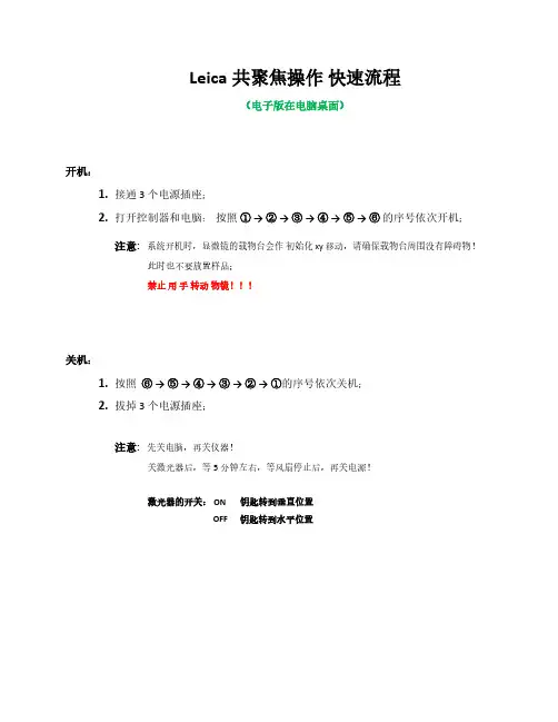
Leica共聚焦操作快速流程(电子版在电脑桌面)开机:1.接通3 个电源插座;2.打开控制器和电脑:按照①→ ②→ ③→ ④→ ⑤→ ⑥的序号依次开机;注意:系统开机时,显微镜的载物台会作初始化 xy 移动,请确保载物台周围没有障碍物!此时也不要放置样品;禁止用手转动物镜!!!关机:1.按照⑥→ ⑤→ ④→ ③→ ②→ ①的序号依次关机;2.拔掉3个电源插座;注意:先关电脑,再关仪器!关激光器后,等5分钟左右,等风扇停止后,再关电源!激光器的开关: ON 钥匙转到垂直位置OFF 钥匙转到水平位置软件快速操作:1.在桌面上,双击打开显微镜控制软件的图标“LAS AF ”:2.出现如下图标,直接点击“OK ”直接点击“ OK ”3.进入软件操作界面后,点击“Configuration ”(1),然后点击“Laser Config ”(2),再打开所需要的激光器开关“ON/OFF ”(3);1324.点击“Acquire ”;点击“SEQ ”125.选择物镜;注意:禁止用手转动物镜!!!选择物镜6.有多个染料需要多个通道时,点击“+ ”增加通道;7.比如:选中“Seq. 1 ”后,打开405激光器;选择探测器PMT 1;选择染料DAPI;2 138. 然后选中“ Seq. 2 ”后 , 打开488激光器 (不关Laser 405,激光强度调到0);选择探测器PMT 2;选择染料Alexa 488; 如果需要DIC 图像,则打开探测器“PMT Trans ”;注意: 探测器探测激发波长的范围 不能 与激光线重合!【 没有特殊需求,不要用“HyD 3”探测器!! 】123少用HyD3DIC激光强度为09.点击软件左下方的“Live”,进行图像预览;调节“Gain”增加探测器探测信号的灵敏度(一点蓝);调节“Offset”去背景(一片绿);注意: Gain值必须小于 800 !!这里可以结合增加激光强度和Gain值来调荧光信号。
激光共聚焦显微镜操作指南说明书
激光共聚焦显微镜操作指南说明书激光共聚焦显微镜(Laser Scanning Confocal Microscope)是一种高分辨率、高对比度的显微镜,广泛应用于生物医学研究、材料科学等领域。
本操作指南将详细介绍激光共聚焦显微镜的操作流程和基本操作技巧,帮助用户正确、高效地使用该设备。
一、设备准备在开始使用激光共聚焦显微镜前,需要进行以下设备准备:1. 检查电源线和数据线是否连接正常,确保设备供电和数据传输正常;2. 检查激光源是否正常工作,激光功率是否稳定;3. 检查镜头和滤光片是否清洁,清除灰尘和污渍,确保成像质量;4. 准备适当的标本样品,并将其固定在载玻片上。
二、系统启动1. 确保设备处于待机状态,按下电源按钮,等待系统启动;2. 检查系统软件是否正常运行,若出现异常情况,及时联系维修人员进行处理;3. 检查镜头和滤光片的安装是否正确,确保成像时的光路通畅;4. 开启激光源,根据需要选择合适的激光波长和功率;5. 调节扫描镜和物镜的位置,使光线准确聚焦在样品上。
三、图像获取1. 打开激光共聚焦显微镜软件,并根据需要选择合适的成像模式;2. 调节激光功率和增益,确保图像的亮度和对比度适宜;3. 调节扫描镜的扫描速度,根据样品的要求选择合适的扫描速度;4. 调节焦距和聚焦位置,通过手动或自动对焦功能获取清晰的图像;5. 点击图像捕捉按钮,记录当前图像或录制图像序列。
四、图像处理和分析1. 通过激光共聚焦显微镜软件提供的图像处理功能,对图像进行调整和增强,以获得更好的观察效果;2. 根据需要,利用软件提供的计算和分析功能对图像进行进一步处理,如三维重建、光学切片等;3. 对图像进行定量分析时,选择合适的工具和算法,并按照要求设定参数;4. 记录和保存处理后的图像数据,以备后续分析和报告撰写使用。
五、设备关闭1. 停止图像采集和处理工作;2. 降低激光功率,关闭激光源;3. 将扫描镜和物镜返回初始位置,关闭设备;4. 断开电源和数据线,保持设备清洁干燥。
Leica Stellaris 5 激光扫描共聚焦显微镜使用说明书

Pod A:Leica Stellaris5Laser Scanning Confocal MicroscopeKyle Marchuk Austin Edwards Mohammad Naser Harrison WismerMay2023Contents1Introduction2 2Start-Up2 3Focusing Your Sample3 4Initial Image Setup64.1Dye Assistant (6)4.2Manually Creating Sequences (7)4.3Optimizing the Fluorescence Signals (7)5Imaging Parameters85.1XY Tab (8)6Imaging Modules96.1Z-Stack (9)6.2Navigator (10)7Saving Acquired Images12 8Other Imaging Tips128.1Project Naming and Saving (12)8.2USB Control Panel (13)8.3Fast Live Settings (13)9Shut Down141IntroductionThe Leica Stellaris5is an inverted laser scanning confocal with4laser lines(405nm,488nm,561nm,and638 nm).It features3next-generation Hybrid Detectors(HyDs).All new users need to be trained by a BIDC staff member before independent use.Sign up for time using the iLab microscope scheduler.The objectives available for use on the Stellaris5are:Objective Mag NumericalAperture Immersion WorkingDistanceID NumberHC PL Fluotar5x0.15Air13.7mm506224 HC PL APO CS220x0.75Air0.62mm506517 HC Fluotar VISIR25x0.95Water 2.40mm506375 HC PL APO CS240x 1.30Oil0.24mm506358 HC PL APO63x 1.40Oil0.14mm506350 2Start-Up1.Turn On the two power switches on the left side of the microscope control box.See Figure:1.NOTE:The key should always be On and the microscope power box should always be On.Figure1:The power supply switches located to the left of the computer desk.2.Turn On the computer tower.3.Log into the User account.unch the LAS X software from the desktop.5.Confirm that the machine configuration and the DMI8microscope are selected at the first prompt.SeeTop Figure:2.6.Ensure the stage area is clear of obstructions and Initialize the stage in the second prompt.See BottomFigure:2.Figure2:The two prompts to launch the software.3Focusing Your Sample1.Select your objective in the software(See Top Figure: 3.)or on the front panel of the microscope(SeeBottom Figure:3.).Figure3:Options for selecting the objectives.2.Add an immersion media to the objective if needed.3.Place your sample into the appropriate sample holder.4.Add the sample holder to the stage.e the xy-stage controller to align the sample above the objective.6.On the front of the microscope navigate to the filter panel menu.See Red square Figure:4.7.Select FLUO for the Incident light.See Blue square Figure:4.8.Press the IL-Shutter to shine light on the sample.See Green square Figure:4.9.Slowly raise the objective using the z-control until your sample comes into focus.Figure4:Widefield illumination panel.4Initial Image Setup4.1Dye AssistantFigure5:Dye Assistant Interface.The Dye Assistant is a useful tool to quickly generate acquisition sequences for multiple fluorophores.The software can optimize for speed of acquisition or minimal fluorescence bleedthrough between channels.1.Click on the Dye Assistant Icon near the top-middle of the main screen.See...2.Press the’...’Icon and search for your fluorophore.3.Continue until all fluorophores are added.4.Apply one of the proposed sequences.None Sequential:All channels will be acquired simultaneously.This is the fastest option,but it is limited to3channels.This will likely have the most Crosstalk of the suggested settings.Line Sequential:Switches Sequences each line of the images scanned.To maximize speed,Channels that share a Detector need to have the same Bandpass width.Frame Sequential:Switches Sequences at the end of each image plane.No limitation on the width of the Bandpass window.Switching the hardware this way increases time.Stack Sequential:Switches Sequences at the end of each Stack.Considerably faster than Frame Se-quential and no limitation on Bandpass width.5.Once a sequence in the Dye Assistant has been selected,the program will ask if you want to turn on thelasers needed for imaging.Select Yes.6.Ensure the microscope arm is in place prior to going Live.4.2Manually Creating SequencesFigure6:Sequence Interface.1.Press the’+’Icon to add the number of Sequences you would like.2.Search for a fluorophore in the Search Bar.3.Drag the fluorophore Icon down to the Sequence you want to place it in.4.Continue adding all your fluorophores to the Sequences.5.Choose whether you want Line Sequential,Frame Sequential,or Stack Sequential by choosing theappropriate Icon(see above).6.When you are happy with your Sequence you can Save it to your directory by pressing the Down ArrowIcon.4.3Optimizing the Fluorescence SignalsFigure7:Tools to quickly optimize your image intensity.1.Click Live or Fast Live in the lower-left of the screen to start imaging the selected Sequence.2.Ensure the sample is in the imaging plane by adjusting the Z-position using the dial on the smart panel.You may need to adjust the Look up Table(LUT)slider to see signal.3.Select the Over/Under Saturation display for the live images.4.Click on a displayed image to select that channel for gain adjustment.5.Adjust the laser power and gain until you have a bright image just below saturation(blue pixels).6.Click on the Capture Image button to collect and save an image of that Sequence.7.Click on the Start button to collect and save an image of all Sequences.5Imaging ParametersAfter setting up the laser and gain acquisition settings for the sequences,the user can set up the rest of sample acquisition parameters.5.1XY TabFigure8:XY TabIn general,used for setting up XY parameters pertaining to how images are captured.Format:The size of the image in pixels.Suggested size is1024x1024for most applications.Speed:Image acquisition speed.Suggested speed is600Hz.Speed faster than600Hz will require increasing the Zoom of the image.Bidirectional X:Data is collected on both movement directions of the X galvo.Some acquisition parameters are tied to this setting.Zoom Factor:Digital Zoom of the image.Increasing the magnification of the objective will give a better image and optical section capability.Zoom In:Press this button to draw an ROI on the image.The microscope will zoom on the ROI.Image Size:Describes the size of the image in microns.This is dependent on the Objective,Format,and Zoom Factor.Pixel Size:Describes the size of the pixel in microns.Optical Section:Thickness of the image plane.Pixel Dwell Time:Length of data collection for each pixel.Frame Rate:Time required to collect a single sequence at a given image plane.Line Average:Number of times each line of the image will be acquired and averaged to produce the image.Used to reduce noise.Line Accu:Number of times each line is accumulated(summed)to produce and image.Can be used on very dim samples.Frame Average:Number of times each frame of the image will be acquired and averaged to produce the ed to reduce noise.Frame Accu:Number of times each frame is accumulated(summed)to produce and image.Can be used on very dim samples.Auto Gain:The system will increase the gain to optimize the image with the current laser power.Rotation:Rotation of the image.Pinhole:Used to adjust the pinhole size.Increasing the pinhole produces a brighter signal at the expense of your optical section capability.6Imaging Modules6.1Z-StackFigure9:Available settings for the volume acquistion.Used for creating the volumes of a3D stacked image.Begin:Using the Z-Position knob,move the image plan to the Top of your sample and press this button to assign this position.End:Using the Z-Position knob,move the image plan to the Bottom of your sample and press this button to assign this position.Trash Can Icon:Deletes your position assignments.Stack Direction(Z):Scanning direction for the volume acquisition.Typically,you want to move the stage toward the objective to scan into your sample.Number of Steps:Volume divided by Z-Step Size.Z-Step Size:Volume divided by Number of Steps.System Optimized:Determined by the objective;the smallest Z-Step Size before over-sampling the volume. Z-Compensation:Is used to associate laser power and gain with z-position.Typically,it is used to compensate for scattering in a thick sample.1.Check which options you’d like to associate with z-position.Excitation Gain is laser intensity.Emis-sion Gain is the HyD gain.2.Navigate to an imaging plan within your volume and adjust the laser intensity and HyD gain to yoursatisfaction.3.Move to other planes and repeat the process.4.Delete any positions you do not need or may have loaded when you started.5.Select your next Sequence and repeat the process.Travel Range:Full distance the z-stage can travel.6.2NavigatorThe Navigator Module is a large-area exploration tool that is capable of setting up multiple ROIs of different sizes for tiled-image acquisition.The navigator can be opened by clicking the grid icon in the top left corner of the main LAS X window.Figure10:Navigator IconOnce open,you should see a white box on a gray background.This box represents the current field of view of the stage.When opening the navigator for the first time,this box will be located at last field of view seen in the main software window.Beam Path Tab On the Stellaris,individual settings can be temporarily turned on and off by checking and unchecking the box in the top left corner of each setting in the Beam Path tab.Having less settings active when spiraling will greatly increase the tile it takes to create a tiled preview.Moving the Stage:Double-click on the viewing area and the stage will move and take a preview tile using the currently selected sequence.Live:Press the Live button to continuously view the current stage position depicted by the white box.Fast Live:Press the Fast Live button to continuously view that stage position in a lower resolution(faster than Live).Spiral Press the Spiral button to engage the stage in an expanding pattern for exploration.ROIs Using the ROI shape tools,draw ROIs on the stage area for exploration or experiment acquisition.Figure11:ROI&Focus Map tools located at the bottom-center of the screenPreview Press Preview and the microscope will do a fast acquisition of the drawn ROIs.Start Press Start to run the experiment from the Navigator.Any ROIs created for tiling will be listed in the tab in the bottom right of the screen.Shapes can be either deleted or temporarily turned off using this tab.Figure12:List of all created ROI shapes to be imaged.Focus Map For uneven tissues,individual focus points can be manually placed and each associated with a unique Z position in order to correct for the uneveness of the sample.1.Select either the blue focus point or green auto-focus point from the options next to the ROI tools.See Figure11.2.The Focus Map option will now be illuminated.Select Focus Map,and click on the first focus pointlisted.3.The software will zoom in on a live view of the field of view surrounding the selected focus point.Adjust the Z position until the sample is in the desired focal plane.4.Once satisfied,select Set Z to associate the focus point with the current Z position.5.Hit Next.Then repeat steps3-5for each focus point placed.Figure13:Focus Map Tab7Saving Acquired Images1.Click the Experiments tab to view all images taken.2.Delete or Rename images as needed.3.Click Save All to save images as a.lif file to your hard drive.4.Please remove old files from the Stellaris computer once they have been saved on your hard drive or Box. 8Other Imaging Tips8.1Project Naming and SavingIt is important to adopt a project naming and saving convention to avoid future headaches when trying to analyze the data.1.Save your Project file with a name that identifies the experiment.We recommend this to be either a slideidentifier or an experiment identifier with a date.2.Rename the images within the Project file with descriptions of the image type.We recommend makingnote of whether the images are z-stack,tiles,timelapse,etc.This will make it easier to’unpack’the imageslater.8.2USB Control PanelFigure14:Can be customized for your workflow.The USB Control Panel can be customized to include controls you may want to readily access.For example, the xy stage position can be controlled similarly to the z-piezo.To add additional features:1.Press the USB Panel shortcut button.2.Select a dropdown and change it to x Position(Stage).3.Select another dropdown and change it to y Position(Stage).To change the speed at which the z-stage moves:1.Located below the Z-Position dropdown(far right):2.Select the speed you wish the stage to move per full turn of the wheel on the USB bar.8.3Fast Live SettingsFigure15:Interface for the Fast Live settings.Pressing the Fast Live’gear’icon allows you to change the XY imaging settings while in Fast Live.The BIDC recommends256x256at600Hz with Bi-Directional scanning On.9Shut Down1.After saving,close the LAS X software.2.Shut down the computer using Shut Down option in the Start Menu.3.Remove samples and clean objectives as needed.4.Press the two Power Switches to turn off the entire system.5.Replace dust cover and clean the area.Contact the BIDCThe BIDC office is located in Medical Sciences Building Room S1109.The BIDC office phone number is415-476-4550.If you need immediate assistance and no one is available in the office,or it is after business hours,please call the BIDC Hotline at415-745-2432.。
Leica TCS SP5中文手册 by jennifer

Leica TCS SP5 简明操作规程一、开机1. 依次打开电脑桌右侧“PC Microscope”、“Scanner Power”及“Laser Power”三个圆形按钮,然后将“Laser Power”按钮右侧的激光开关钥匙(Laser Emission)顺时针旋转90度至“On-1”位置。
如图1-1。
记录开机时间。
图1-1 SP5系统开关2. 打开显微镜电源(如图1-2),及荧光电源。
荧光系统若以汞灯为光源,参照图1-3;若以金属卤素灯为光源,参照图1-4。
如有必要,记录荧光灯使用时间。
图1-2 显微镜电源(1.指示灯;2.电源开关)图1-3 汞灯电源(1.电源开关;2.汞灯使用时间显示)图1-4 EL6000荧光电源(1.电源开关;2.使用时间显示;3.光闸;4.光强控制) 3. 双击电脑显示屏桌面上的“LAS AF”图标启动徕卡共聚焦软件。
如图1-5。
图1-5 LAS AF图标4. 如需使用快扫系统,在“Activate Resonant Scanner”选项前打勾。
如图1-6。
图1-6 快扫或高分辨成像系统模式5. 点击“OK”以打开软件。
如图1-7。
图1-7 LAS AF启动界面系统自检完毕后,显示LAS AF基本界面。
如图1-8。
图1-8 LAS AF基本界面二、在显微镜下观察样品1. 选择合适的物镜,可通过显微镜主机右侧的物镜转换按钮,如图2-1,或软件中的“Objectives”键进行选择,如图2-2。
图2-1 显微镜主机右侧部分(1. 调焦按钮;2. 物镜转换按钮)图2-2 通过软件选择物镜2. 将样品置于载物台上,在明场条件下选择合适的视野。
通过显微镜主机右侧的调焦按钮或旋钮调节至合适的z 轴平面,通过显微镜主机左侧的“INT”功能键调节光强。
如图2-3。
2图2-3 显微镜主机左侧部分功能键 (1.透射与反射切换;2.孔径光阑调节;3.光强调节;4.视场光阑调节)3. 按“TL/IL”功能键转换至荧光观察方法,通过显微镜前面板的按钮选择合适的荧光滤块,进行样品的荧光观察。
Leica激光扫描共聚焦显微镜快速操作手册

2
7
1 6
3 4
5
1 研究级显微镜 2 扫描头
8
10
9
11
3 防震台 4 EL6000荧光激发光源 5 显微镜控制器
6 遥控手轮
12 13
7 显示器 8 控制面板 9 键盘
10 电脑鼠标
14
11 电脑桌
12 CSU 13 电源控制 14 电脑主机
Leica TCS SP8正置,配备紧凑型光源组件(CSU)
物镜选择按钮 预览按钮 Live 拍摄按钮 叠加图像显示按钮,在使用两个或以上数量通道拍摄多色图像时,用于显示 所有通道叠加后的图像
7
2.3 在显微镜下观察样品
2.3.1 选择物镜:可通过显微镜主机右侧的物镜转换按钮,或软件中的“Objectives” 键进行选择。(如下图)(注意:有时,显微镜主机上的物镜转换按钮不能在干镜 和油镜或水镜之间切换,软件中都可以切换)
2
Leica TCS SP8基本系统组成
1 2
3 4
7 6
5
Leica TCS SP8倒置,配备灵活型光源组件(FSU)
8
9
10 11
13 12
14
1 研究级显微镜 2 扫描头 3 防震台 4 EL6000荧光激发光源 5 显微镜控制器 6 遥控手轮 7 显示器 8 控制面板 9 键盘 10 电脑鼠标 11 电脑桌 12 FSU 12.1 开机顺序 (硬件标号请参考前面的系统组成图)
(1)因为 FSU 和 CSU 硬件的电源控制 )不同,请分别按照如下步骤开机:
FSU 系统
CSU 系统
依次打开“PC Microscope”、“Scanner Power”、 先按电脑主机上的电源按钮启动电脑,再打
Leica激光共聚焦显微镜 操作规程

潍坊医学院医学研究实验中心仪器简明操作规程汇编
激光共聚焦显微镜简明操作规程
1. 启动
开启UPS电源,依次开启右侧手柄上的三个开关,从左至右顺序开启,最后开启激光钥匙。
2. 开启软件
电脑进入操作系统界面后,双击电脑桌面启动共聚焦操作软件。
3. 自检
点击对话框的“OK”键进行自检,结束后进入软件界面
4. 开启激光管
点击屏幕上方的“configuration”按钮进入配置界面→点击左边
按钮→打开所需激光(OFF →ON ),Argon激光还需拖动右方滑块以调节输出功率
5. 设置参数
6. 放置样品进行观察。
7. 观察结束保持数据。
8.关机,做好记录。
激光共聚焦扫描显微镜操作规程
激光共聚焦扫描显微镜操作规程一.开机程序1.开启总电源,确认所有仪器电源状态正常工作2.开启电脑,双击桌面上的LSM510图标,开启显微镜。
3.在初始平面上点击Start Expert Mode 键开启专家拍摄模式。
4.在主菜单中点击File New键,建立新的数据库。
二.软件拍摄1.在主菜单上点击Acquire Laser键,开启需要使用的激光2.在主菜单上点击VIS键,开启显微镜观察模式3.把需要观察的玻片放到载物台上选择需要观察的平面4.在主菜单上点击LSM键,开启进入显微镜激光扫描模式5.在主菜单上点击Config键,选择所需要扫描的模式及参数6.在主菜单上点击Scan Find键,进行图像参数自动校正7.在Scan子菜单下点击Fast X键,进行层面选择8.在连续扫描中调节放大器增益、补偿;激光强度等图像参数来优化图像9.点击图像子菜单上的Save键存储优化好的图像三.关机程序1.完成所有操作后,关掉激光开关,冷却5分钟后,点击主菜单上Exit键,退出所有程序2.关闭电脑3.关闭电源ZEISS 510 MET A二维扫描程序1.在Acquire → config →确定扫描所需的波长,(如果已作过相同方法的扫描,可直接调出一张相同条件的图像,用图像窗中的Reuse确定有关的扫描条件)2.在Acquire → micro →在低倍镜(透射光或荧光)下找到要观察的图像3.在Scan control → mode → find →在显示器上找到图像,选定扫描需用的分辨率4.调节物镜到适当的放大倍数5.Scan control → mode →New,打开一新图像窗6.在Scan control → mode → cont →用zoom将图像大小调至最佳,用Pinhole(一般选1)、Detector Gain(650左右,不宜时间超过800,也不宜低于500)、Amplifier offset(不宜过低),以及选择作算术平均值次数、调节激光强度(488nm不超过25%)等调节图像质量至最佳。
Leica共聚焦操作快速流程
Leica共聚焦操作快速流程(电子版在电脑桌面)开机:1.接通3 个电源插座;2.打开控制器和电脑:按照①→ ②→ ③→ ④→ ⑤→ ⑥的序号依次开机;注意:系统开机时,显微镜的载物台会作初始化 xy 移动,请确保载物台周围没有障碍物!此时也不要放置样品;禁止用手转动物镜!!!关机:1.按照⑥→ ⑤→ ④→ ③→ ②→ ①的序号依次关机;2.拔掉3个电源插座;注意:先关电脑,再关仪器!关激光器后,等5分钟左右,等风扇停止后,再关电源!激光器的开关: ON 钥匙转到垂直位置OFF 钥匙转到水平位置软件快速操作:1.在桌面上,双击打开显微镜控制软件的图标“LAS AF ”:2.出现如下图标,直接点击“OK ”直接点击“ OK ”3.进入软件操作界面后,点击“Configuration ”(1),然后点击“Laser Config ”(2),再打开所需要的激光器开关“ON/OFF ”(3);1324.点击“Acquire ”;点击“SEQ ”125.选择物镜;注意:禁止用手转动物镜!!!选择物镜6.有多个染料需要多个通道时,点击“+ ”增加通道;7.比如:选中“Seq. 1 ”后,打开405激光器;选择探测器PMT 1;选择染料DAPI;2 138. 然后选中“ Seq. 2 ”后 , 打开488激光器 (不关Laser 405,激光强度调到0);选择探测器PMT 2;选择染料Alexa 488; 如果需要DIC 图像,则打开探测器“PMT Trans ”;注意: 探测器探测激发波长的范围 不能 与激光线重合!【 没有特殊需求,不要用“HyD 3”探测器!! 】123少用HyD3DIC激光强度为09.点击软件左下方的“Live”,进行图像预览;调节“Gain”增加探测器探测信号的灵敏度(一点蓝);调节“Offset”去背景(一片绿);注意: Gain值必须小于 800 !!这里可以结合增加激光强度和Gain值来调荧光信号。
Leica TCS SPE共聚焦显微镜操作规程(1)
Living up to Life
Page 9
共聚焦——三维层切
1. 单击 Live进行预览,调至合适的 焦平面,再调节激光强度、接收 范围、PMT Gain和Offset等参数 2. 单击Set Plane记录焦平面位置
Living up to Life
3. 继续预览,改变 z 轴层面以确定 层切的起点和终点,红色表示已 设定
开软件
1. 系统进行自检,在此过 程中不要触碰显微镜 2. 自 检 完 毕 之后 ,显 示 LAS AF基本界面
Living up to Life
在显微镜下观察样品
1. 选择合适的物镜 2. 将样品放置于载物台上,盖玻片 一侧靠近物镜 3. 在明场下观察样品。调节载物台 xy 手柄 及 调焦旋钮,寻找合适的 焦平面及视野
4. 采用系统优化值;也可单击 Nr. of steps 设置层切数, 或层切间距 5. 设置扫描分辨率、速度和平 滑次数 6. 单击Start按键开始三维层切
Page 10
共聚焦——时间序列扫描
1. 选择xyt模式 2. 单击 Live 进行预览,调至合适的焦 平面,再调节激光强度、接收范 围、PMT Gain和Offset等参数 3. 停止预览 4. 设置采图的 时间间隔 ,也可选择 Minimize 5. 选择时间模式 1) 连续采图直至手动停止 2) 设置采集总时间 3) 设置采集帧数 6. 按回车键或单击 Apply 记录上述设 置 7. 单击Start按键进行时间序列扫描
Living up to Life
2. 设置扫描速度 (Speed)
3. 设置平滑次数 (Frame Aveage 按键 进行图 像采集
Page 8
共聚焦——多通道采集
Leica TCS SP5 简明操作规程
Leica TCS SP5 简明操作规程一、开机1. 依次打开电脑桌右侧“PC Microscope”、“Scanner Power”及“Laser Power”三个圆形按钮,然后将“Laser Power”按钮右侧的激光开关钥匙(Laser Emission)顺时针旋转90度至“On-1”位置。
如图1-1。
记录开机时间。
图1-1 SP5系统开关2. 打开显微镜电源(如图1-2),及荧光电源。
荧光系统若以汞灯为光源,参照图1-3;若以金属卤素灯为光源,参照图1-4。
如有必要,记录荧光灯使用时间。
图1-2 显微镜电源(1.指示灯;2.电源开关)图1-3 汞灯电源(1.电源开关;2.汞灯使用时间显示)图1-4 EL6000荧光电源(1.电源开关;2.使用时间显示;3.光闸;4.光强控制) 3. 双击电脑显示屏桌面上的“LAS AF”图标启动徕卡共聚焦软件。
如图1-5。
图1-5 LAS AF图标4. 如需使用快扫系统,在“Activate Resonant Scanner”选项前打勾。
如图1-6。
图1-6 快扫或高分辨成像系统模式5. 点击“OK”以打开软件。
如图1-7。
图1-7 LAS AF启动界面系统自检完毕后,显示LAS AF基本界面。
如图1-8。
图1-8 LAS AF基本界面二、在显微镜下观察样品1. 选择合适的物镜,可通过显微镜主机右侧的物镜转换按钮,如图2-1,或软件中的“Objectives”键进行选择,如图2-2。
图2-1 显微镜主机右侧部分(1. 调焦按钮;2. 物镜转换按钮)图2-2 通过软件选择物镜2. 将样品置于载物台上,在明场条件下选择合适的视野。
通过显微镜主机右侧的调焦按钮或旋钮调节至合适的z 轴平面,通过显微镜主机左侧的“INT”功能键调节光强。
如图2-3。
2图2-3 显微镜主机左侧部分功能键 (1.透射与反射切换;2.孔径光阑调节;3.光强调节;4.视场光阑调节)3. 按“TL/IL”功能键转换至荧光观察方法,通过显微镜前面板的按钮选择合适的荧光滤块,进行样品的荧光观察。