theben TR610定时器说明书
多功能定时器的用户手册说明书
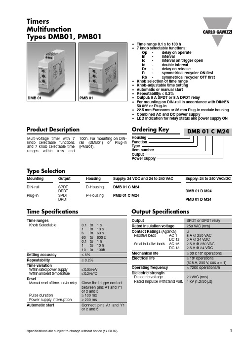
•Time range 0.1 s to 100 h•7knob selectable functions:Op-delay on operateIn-intervalIo-interval on trigger openId-double intervalDr-delay on releaseR-symmetrical recycler ON firstRb-symmetrical recycler OFF first•Knob selection of time range•Knob-adjustable time setting•Automatic or manual start•Repeatability: ≤0.2%•Output: 8 A SPDT or 8 A DPDT relay•For mounting on DIN-rail in accordance with DIN/EN50 022 or Plug-in•22.5 mm Euronorm or 36 mm Plug-in module housing •Combined AC and DC power supply•LED indication for relay status and power supply ONMulti-voltage tim er with 7 knob selectable functions and 7 knob selectable tim e ranges within 0.1s and 100h. For mounting on DIN-rail (DMB01) or Plug-in (PMB01).TimersMultifunctionTypes DMB01, PMB01Product DescriptionType SelectionMounting Output Housing Supply: 24 VDC and 24 to 240 VAC Supply: 24 to 240 VAC/DC DIN-rail SPDT D-Housing DMB 01 C M24DPDT DMB 01 D M24Plug-in SPDT P-Housing PMB 01 C M24DPDT PMB 01 D M24Time Specifications Output SpecificationsDMB 01PMB 01DMB01, PMB01Function OpDelay on operateThe tim e period begins as soon as the trigger contact is closed.At the end of the set delay tim e the relay operates and doesn't release until the trig-ger contact is closed again or the power supply is dis-connected. If the trigger contact is closed before the end of the delay tim e, the device resets and a new time period starts.Function In IntervalThe relay operates and the tim e period begins as soon as the trigger contact is closed. The relay releases at the end of this period or when the power supply is disconnected. The relay operates again when the trigger contact is closed again. If the trigger contact is closed before the end of the delay tim e, the relaykeeps ON and a new tim e period starts.Function IoInterval on trigger open The relay operates and the tim e period begins as soon as the trigger contact is opened. At the end of the set delay or when the power supply is disconnected the relay releases. The relay operates again when the trigger contact is opened again. If the trigger contact is opened before the end of the delay tim e the relay keeps ON and a new tim e period begins.Function Id Double intervalThe relay operates and the tim e period begins as soon as the trigger contact is closed. The relay releases at the end of this period or when the power supply is disconnected. When the trigger contact is openedthe relay operates again for the set delay period. If the trigger contact is opened before the end of the first tim e period the second one begins; if the trigger contact is closed before the end of the second tim e period the relay keeps ON and the first time period begins again.Function DrDelay on releaseThe relay operates as soon as the trigger contact is closed. The tim e period begins when the trigger con-tact is opened. The relay releases at the end of the set delay tim e or when the power supply is disconnect-ed. The relay operates again when the input contact is closed again. If it is closed before the end of the delay tim e the relay keeps ON, a new tim e period begins as soon as the contact is opened again.Function RSymmetrical recycler, ON-time period firstThe relay operates and the tim e period begins as soon as the input contact is closed. After the set delay period the relay releases for the sam e tim e period. This sequence continues with equal ON- and OFF-tim e periods until the power sup-ply is interrupted.Function RbSymmetrical recycler,OFF-time period firstThe tim e period begins as soon as the input contact is closed. The relay is OFF during the set delay period,after this time it operates for the sam e tim e period. This sequence continues with equal OFF- and ON-tim e periods until power supply is interrupted.Supply SpecificationsGeneral SpecificationsFunction and Time SettingMode of OperationUpper knob:Setting of function:Op -delay on operate In -intervalIo -interval on triggeropenId -double interval Dr -delay on releaseR -symmetrical recycler(ON first)Rb -symmetrical recycler(OFF first)Centre knob:Tim e setting on relative scale: 1 to 10 with respect to the chosen range.Lower knob:Setting of time range.DMB01, PMB01Additional LoadIt's possible to wire an addi-tional load (i.e. a relay) between pins Y1 and A2, or 5and 10, driven by the trig-ger contact without dam ag-ing the device (see wiringdiagram).Yellow LED working modeTiming: Slow blinkingRelay ON: See operationdiagramsIncorrect knobs position:Fast blinkingMode of Operation (cont.) Operation DiagramsOperation Diagrams (cont.)DMB01, PMB01DimensionsWiring Diagrams。
TR610 top2-简易版-0970307
如為重新設定,於選擇完使用語言後,以“◄”“►”按鍵選擇保留先前設定程式(RETAIN PROGRAMS)或刪除先前設定程式(DELETE PROGRAMS);
若選擇刪除先前設定程式(DELETE PROGRAMS)按 OK 鍵,螢幕會出現”CONFIRM”,按 OK 鍵確認刪除,此時會依序出現”DELETE”及”DELET明
● “一次有效"功能: “一次有效"即在自動控制模式下,可手動改變輸出狀態,而不影響後續之 自動功能。《方法: “◄”與“►”按鍵同時按下即放 》
● “永久有效"功能: “永久有效"即在自動控制模式下,可手動改變輸出狀態,而影響後續自動 功能,使輸出狀態改變為持續性狀態,一直到再次手動改變輸出狀態取消此 功能。《方法:“◄”與“►”按鍵同時按下約 2 秒再放;待再次手動將“◄”與“►” 按鍵同時按下即放,解除“永久有效"設定,定時器才會恢復自動控制模式。》
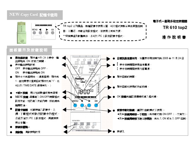
顯示目前的時間。
顯示目前可使用的功能按鍵。
OK 按鍵為確認選擇鍵或進入程式鍵。
直接手動切換鍵(僅限於自動模式下使用)。 ◄及►按鍵同時按一下即放:為手動切換 ON/OFF(一次有效)。 ◄及►按鍵同時按下約 2 秒再放:為永久 ON 或永久 OFF 控制。
接線孔
功能瀏覽
基本設定
1.
設定操作顯示使用語言:
● 將電纜剝線約 8mm ~ 9mm 成裸銅線。 ● 將電纜以 45°角的方式插入,電纜就會完全
卡住。(如右圖所示) ● 若要解除安裝,請用螺絲起子壓住接線按壓
點後,再將電纜拔出,以免電纜卡在接線孔 內。
NEW-Copy Card 記憶卡使用
TR top2 系列商品,新增記憶卡使用介面,可將程式複製至其他同型控制 器,不需逐一手動各別設定程式,在使用上更為方便。 **另有模組及軟體套件,亦可於 PC 上設定記憶卡程式。
Eaton 品牌的变压器时间延迟器 TR 系列产品指南说明书
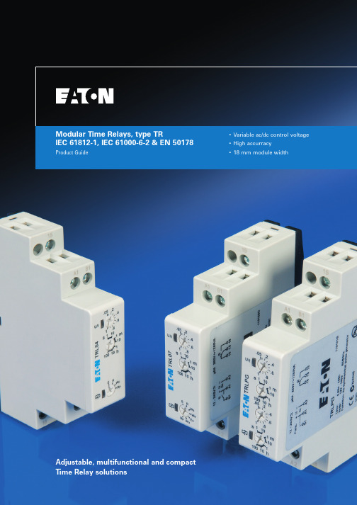
Modular Time Relays, type TRIEC 61812-1, IEC 61000-6-2 & EN 50178 Product Guide •Variable ac/dc control voltage •High accurracy•18 mm module widthAdjustable, multifunctional and compact Time Relay solutionsModular time relays, type TR12Modular time relays, type TR PG04910001U - July 2006Modulartimerelays,typeTR1Eaton time relays including all time delay functionsFor further details about the different functionalities of time relays, are explained in chapter 2.Here you find a detailed description of the individual functionalities, supported by pictograms.Reference of available functions by typeType TRL04TRL07TRLPGFunctionON Delay (voltage controlled)X XOFF Delay (with control input)X XSingle shot leading edge (with control input)XSingle shot trailing edge (with control input)XON Delay (with control input)XSingle shot leading edge (voltage controlled)X XSymmetric pulse generator (pause first)X XAsymmetric pulse generator (pause first)XAsymmetric pulse generator (pulse first)X3PG04910001U - July 2006Modular time relays, type TRM o d u l a r t i m e r e l a y s , t y p e T R1Available functions are:E = ON Delay (voltage controlled)R = OFF Delay (with control input)Wu = Single shot leading edge (voltage controlled)Bp = Symmetric pulse generator (pause first)Available functions are:E = ON Delay (voltage controlled)R = OFF Delay (with control input)Ws = Single shot leading edge (with control input)Wa = Single shot trailing edge (with control input)Es = ON Delay (with control input)Wu = Single shot leading edge (voltage controlled)Bp = Symmetric pulse generator (pause first)Available functions are:Ip = Asymmetric pulse generator (pause first)Ii = Asymmetric pulse generator (pulse first)TRL04DescriptionAvailable functionsNominal current Contact configurationSupply & controlvoltage inputWidthQPCEatonlist numberTime relay, multifunctional - with 4 functionsE, R, Wu, Bp 8 A 1 co 24…240 Vac/dc 18 mm 1TRL04TRL07DescriptionAvailable functionsNominal currentContactconfigurationSupply & control voltage inputWidthQPCEatonlist numberTime relay, multifunctional - with 7 functions E, R, Ws, Wa, Es, Wu, Bp 8 A1 co 12…240 Vac/dc 18 mm 1TRL07TRLPGDescriptionAvailable functionsNominal current Contact configurationSupply & controlvoltage inputWidthQPCEatonlist numberTime relay, asymmetric pulse generatorIp, Ii 8 A 1 co 12…240 Vac/dc 18 mm 1TRLPGModular time relays, technical details24Modular time relays, technical details PG04910001U - July 2006Modulartimerelays,technicaldetails2ON Delay - voltage controlled (E)When the supply voltage U is applied, the set interval t begins (green LED U/t flashes). After the interval t has expired(green LED U/t illuminated) the output relay R switches into on-position (yellow LED illuminated). This status remains until the supply voltage is interrupted. If the supply voltage is interrupted before the expiry of the interval t, the interval already expired is erased and is restarted when the supply voltage is next applied.OFF Delay - with control input (R)The supply voltage U must be constantly applied to the device (green LED U/t illuminated). When the control contact S is closed, the output relay R switches into on-position (yellow LED illuminated). If the control contact is opened, the set interval t begins (green LED flashes). After the interval t has expired (green LED U/t illuminated) the output relay switches into off-position (yellow LED notilluminated). If the control contact is closed again before the interval t has expired, the interval already expired is erased and is restarted.Single shot leading edge - with control input (Ws)The supply voltage U must be constantly applied to the device (green LED U/t illuminated). When the control contact S is closed, the output relay R switches into on-position (green LED U/t illuminated) and the set interval t begins (green LED U/t flashes). After theinterval t has expired (green LED U/t illuminated) the output relay switches into off-position (yellow LED not illuminated). During the interval, the control contact can be operated any number of times. A further cycle can only be started when the cycle run has been completed.Single shot trailing edge - with control input (Wa)The supply voltage U must be constantly applied to the device (green LED U/t illuminated). Closing the control contact S has noinfluence on the condition of the output R. When the control contact is opened, the output relay switches into on-position (yellow LED illuminated) and the set interval t begins (green LED U/t flashes). After the interval t has expired (green LED U/t illuminated), the ouput relay switches into off-position (yellow LED not illuminated). During the interval, the control contact can be operated any number of times. A further cycle can only be started when the cycle run has been completed.Time relays, reference of available functions by type.5PG04910001U - July 2006Modular time relays, technical detailsM o d u l a r t i m e r e l a y s , t e c h n i c a l d e t a i l s2ON Delay - with control input (Es)The supply voltage U must be constantly applied to the device (green LED U/t illuminated). When the control contact S is closed, the set interval t begins (green LED U/t flashes). After the interval t has expired (green LED U/t illuminated) the output relay R switches into on-position (yellow LED illuminated). This status remains until the control contact is opened again. If the control contact is opened before the interval t has expired, the interval already expired is erased and is restarted with the next cycle.Single shot leading edge - voltage controlled (Wu)When the supply voltage U is applied, the output relay R switches into on-position (yellow LED illuminated) and the set interval t begins (green LED U/t flashes). After the interval t has expired (green LED U/t illuminated) the output relay switches into off-position(yellow LED not illuminated). This status remains until the supply voltage is interrupted. If the supply voltage is interrupted before the interval t has expired, the output relay switches into off-position. The interval already is erased and is restarted when the supply voltage is next applied.Symmetric pulse generator - pause first (Bp)When the supply voltage U is applied, the set interval t begins (green LED U/t flashes). After the interval t has expired, theoutput relay R switches into on-position (yellow LED illuminated) and the set interval t begins again. After the interval t has expired, the output relay switches into off-position (yellow LED not illuminated). The output relay is triggered at a ratio of 1:1 until the supply voltage is interrupted.Asymmetric pulse generator - pause first (Ip)When the supply voltage U is applied, the set interval t1 begins (green LED U/t flashes slowly). After the interval t1 has expired, the output relay R switches into on-position (yellow LED illuminated) and the set interval t2 begins (green LED U/t flashes fast). After the interval t2 has expired, the output relay switches into off-position (yellow LED not illumminated). The output relay is triggered at the ratio of t1:t2 until the supply voltage is interrupted.Asymmetric pulse generator - pulse first (Ii)When the supply voltage U is applied, the output relay R switches into on-position (yellow LED illuminated) and the set interval t1 begins (green LED U/t flashes slowly). After the interval t1 has expired, the output relay switches into off-position (yellow LED not illuminated) and the set interval t2 begins (green LED U/t flashes fast). After the interval t2 has expired, the output relay switches intoon-position (yellow LED illuminated). The output relay is triggered at the ratio of t1:t2 until the supply voltage is interrupted.6Modular time relays, technical details PG04910001U - July 2006M o d u l a r t i m e r e l a y s , t e c h n i c a l d e t a i l s2Time relays, dimensional drawings, type TRTime relays, connection schemes, type TRTime relays, type TRTRL04/TRL07 with control input. TRL04/TRL07 without control input.TRLPG.7PG04910001U - July 2006Modular time relays, technical detailsM o d u l a r t i m e r e l a y s , t e c h n i c a l d e t a i l s2Time relays, technical details, type TRProductsTime relays, type TRTRL04TRL07TRLPGGeneralMain Standards IEC 61812-1, IEC 61000-6-2, EN 50178Additional standards IEC 61000-6-3, IEC 61000-4-2, IEC 61000-4-4, IEC 61000-4-6Protection class open airIP20IP20IP20Protection class enclosed (accessible front)IP40IP40IP40Permissible ambient temperature (acc. IEC 68-1)-25…+55 °C -25…+55 °C -25…+55 °C Storage temperature-25…+70 °C -25…+70 °C -25…+70 °C Relative humidity (acc. IEC 721-3-3 class 3K3)15% to 85%15% to 85%15% tot85%Pollution degree (acc. IEC 664-1)Class 2, if built-in class 3Class 2, if built-in class 3Class 2, if built-in class 3Vibration resistance (acc. IEC 68-2-6)10 to 55 Hz / 0,35 mm 10 to 55 Hz / 0,35 mm 10 to 55 Hz / 0,35 mm Shock resistance (acc. IEC 68-2-27)15 g 11 ms 15 g 11 ms 15 g 11 ms Mounting positionanyanyanyIncoming supply circuitSupply voltage24 - 240 V ac/dc12 - 240 V ac/dc 12 - 240 V ac/dc Supply voltage tolerance 24 V -/- 15%...- 240 V + 10%12 V -/- 10%.....- 240 V + 10%12 V -/- 10%.....- 240 V +10%Incoming supply terminals A1(+) - A2A1(+) - A2A1(+) - A2Rated power consumption 4 VA (1,5W) 4 VA (1,5W) 4 VA (1,5W)Rated frequency for ac voltage 48 to 63 Hz 48 to 63 Hz 48 to 63 Hz Duty cycle 100%100%100%Reset time100 ms 100 ms 100 ms Residual ripple to DC 10%10%10%Drop off voltage> 30% of nominal voltage> 30% of nominal voltage > 30% of nominal voltage Rated impulse withstand voltage U imp4 kV 4 kV 4 kV Overvoltage category (acc. IEC 60664-1)IIIIIIIIIIncoming control circuitControl supply terminals A1-B1A1-B1A1-B1Loadableyes yes yes Maximum cable length 10 mtr.10 mtr.10 mtr.Trigger level (sensitivity)Automatic adaptation to supply voltage Automatic adaptation to supply voltage Automatic adaptation to supply voltage Minimum duration control pulse length at ac 100 ms 100 ms -Minimum duration control pulse length at dc50 ms50 ms-8Modular time relays, technical details PG04910001U - July 2006M o d u l a r t i m e r e l a y s , t e c h n i c a l d e t a i l s2Products Time relays, type TRTRL04TRL07TRLPGOutgoing circuitOutgoing potential free contact 1 x co 1 x co 1 x co Rated voltage250 V ac250 V ac250 V acSwitching capacity ac *)2000 VA (8 A / 250 V)2000 VA (8 A / 250 V)2000 VA (8 A / 250 V)Switching capacity dc *)50 VA50 VA50 VAMaximum lamp load: *)Incandescent lamp 500 VA 500 VA 500 VA Energy saving lamp50 VA 50 VA 50 VA Fluorescent lamp single - Uncompensated (inductive)120 VA 120 VA 120 VA Fluorescent lamp single - Compensated (capacitive)36 VA 36 VA 36 VA Fluorescent lamp double - Series compensated 360 VA 360 VA 360 VA Fluorescent lamp single/double - HF Electronic120 VA 120 VA 120 VA Mechanical endurance20.000.000 x 20.000.000 x 20.000.000 x Electrical endurance at 1000 VA cosphi = 1,0200.000 x 200.000 x 200.000 x Maximum switching frequency at 100 VA pf=1,0 (acc. IEC 947-5-1)60x / min 60x / min 60x / min Maximum switching frequency at 1000 VA pf=1,0 (acc. IEC 947-5-1)6x / min6x / min6x / minMaximum back-up fuse - fast acting 8 A fast 8 A fast 8 A fast Rated impulse withstand voltage U imp4 kV 4 kV 4 kV Overvoltage category (acc. IEC 60664-1)IIIIIIIIIAccuracyBase accuracy ±1% of maximum scale value±1% of maximum scale value±1% vof maximum scale valueAdjusting accuracy < 5% of maximum scale value< 5% of maximum scale value< 5% vof maximum scale valueRepetition accuracy < 0,5% or ±5 ms < 0,5% or ±5 ms < 0,5% or ±5 ms Voltage influence ---Temperature influence< 0,01% / °C< 0,01% / °C< 0,01% / °CDimensions & weightWidth 18 mm 18 mm 18 mm Height87 mm 87 mm 87 mm Depth (excl. DIN-profile)60 mm 60 mm 60 mm Weight72 gram72 gram72 gramTerminals for main & auxiliary contactsTerminal capacity1 x 0,5....2,5 mm2 with/without multicore cable end 1 x 4 mm 2 without multicore cable end 2 x 0,5....1,5 mm 2 without multicore cable end 2 x 2,5 mm 2 flexible with/without multicore cable endTerminal screw head type (Pozidrive)PZ 1PZ 1PZ 1Maximum torque1,0 Nm1,0 Nm1,0 NmNote:*)In case multipole circuits are installed in one panel it is required to multiply above mentioned (lamp)load by the applicable load factor according the IEC 60439-1.+61 2 9693 9388+61 2 9693 1258************************************(toll-freeline)*************************************************************。
最新定时计数器的四种工作方式

定时计数器的四种工作方式在单片机中有两个特殊功能寄存器与定时/计数有关,这就是TMOD和TCON。
顺便说一下,T MOD和TCON是名称,我们在写程序时就能直接用这个名称来指定它们,当然也能直接用它们的地址89H和88H来指定它们(其实用名称也就是直接用地址,汇编软件帮你翻译一下而已)。
从图1中我们能看出,TMOD被分成两部份,每部份4位。
分别用于控制T1和T0,至于这里面是什么意思,我们下面介绍。
从图2中我们能看出,TCON也被分成两部份,高4位用于定时/计数器,低4位则用于中断(我们暂不管)。
而TF1(0)我们上节课已提到了,当计数溢出后TF1(0)就由0变为1。
原来TF1(0)在这儿!那么TR0、TR1又是什么呢?看上节课的图。
希望大家常来本站学习单片机相关知识计数脉冲要进入计数器还真不不难,有层层关要通过,最起码,就是TR0(1)要为1,开关才能合上,脉冲才能过来。
因此,TR0(1)称之为运行控制位,可用指令SETB来置位以启动计数器/定时器运行,用指令CLR来关闭定时/计数器的工作,一切尽在自已的掌握中。
<单片机定时器/计数器结构>定时/计数器的四种工作方式工作方式0定时器/计数器的工作方式0称之为13位定时/计数方式。
它由TL(1/0)的低5位和TH(0/1)的8位组成13位的计数器,此时TL(1/0)的高3位未用。
我们用这个图来讨论几个问题:M1M0:定时/计数器一共有四种工作方式,就是用M1M0来控制的,2位正好是四种组合。
C/T:前面我们说过,定时/计数器即可作定时用也可用计数用,到底作什么用,由我们根据需要自行决定,也说是决定权在我们��编程者。
如果C/T为0就是用作定时器(开关往上打),如果C/T为1就是用作计数器(开关往下打)。
顺便提一下:一个定时/计数器同一时刻要么作定时用,要么作计数用,不能同时用的,这是个极普通的常识,几乎没有教材会提这一点,但很多开始学习者却会有此困惑。
便携式定时提醒器使用说明

便携式定时提醒器使用说明
●一定要将电源指示(非工作指示)的发光二极管摘除,否则耗电量剧增。
●除非长期不使用定时器,一般平时不需要断开电源。
●最好将P0.1、P0.7口各加一个几十KΩ的上拉电阻,可减少不工作状态下的
耗电电流(几μA级)。
●以2~4节1.5V电池供电,极限工作电压范围2V~6V。
●定时时间范围:1分钟~9时59分。
●按复位键后对定时时间进行设置,三个按键以“加1”的方式分别对“时”、
“十分位”、“分位”进行设置。
时间设置后,自动开始定时。
●定时期间,时间不显示,只有指示灯每隔2秒闪亮一下作为运行提示。
如需
要显示,可按一下三个按键中任一个,显示延时三秒钟。
●定时期间,如需修改定时时间,可在显示时间时,按上述设置定时时间的方
法进行修改。
●定时期间,如需取消定时,可长按三个按键中任一个约1秒时间即可,这时
蜂鸣器发出1秒“嘟”声。
●定时时间到,蜂鸣器发出“嘟、嘟、嘟——”的提示声,重复30秒后,本
次定时过程结束。
如果想提前结束音响并关机,此时可按一下三个按键中任一个即可。
●任何时候,当时间显示为“0-00”时,延时三秒后自动关机,同时蜂鸣器
发出1秒“嘟”声。
TR610 top说明书
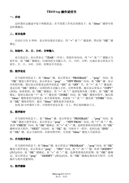
TR610 top操作说明书一:启动定时器在运输途中处于休眠状态,在不需要工作电压的情况下,按“Menu”键即可将定时器激活。
二、语言选择启动后大约3秒钟,显示屏出现语言提示,用“+”或“-”键选择,然后按“OK”键确定。
三:初始年、月、日、小时、分钟输入语言选定后,显示屏显示“YEAR”(年份),原始年份闪动,用“+”或“-”键输入当前年份,按“OK”键确定。
以相同的方式输入月、日、小时、分钟,完成后显示屏显示当前年、月、日、小时、分钟、星期及开关状态。
四、程序设定在当前时间状态下,按“Menu”键,显示屏显示“PROGRAM”,“prog”闪动,按“OK”键进入程序设定,显示屏显示“prog”,“NEW PROG”闪动,按“OK”键,显示可用程序数,稍后显示所要设定程序的状态“ON”或“OFF”关,用“+”或“-”键选择,选定后按“OK”键确定;以相同的方式输入小时、分钟和星期,随后显示屏显示“COPY”(复制),如需复制,按“OK”键确定,用“+”或“-”选择复制对象(星期),按“OK”键确定,复制完成后按“+”或“-”键直到“STORE”闪动,按“OK”键保存程序,随后按“Menu”键恢复到当前状态;如不需要复制,直接按“+”或“-”键直到“STORE”闪动,按“OK”键保存程序,随后“Menu”键恢复到当前状态。
如需24小时循环工作,可将程序设定在某一天上,然后复制剩余六天。
五、程序核对在当前时间状态下,,按“Menu”键,显示屏显示“PROGRAM”,“prog”闪动,按“OK”键进入程序设定,显示屏显示“prog”,“NEW PROG”闪动,按“+”或“-”键,直到“CHECK”闪动,按“OK”键确定,按“+”或“-”键,选择需要核对的星期,按“OK”键核对该天程序,“NEXT”闪动时,按“OK”键,可核对下一程序,直到完成“END”,按“OK”键,显示当前时间。
在核对程序时,可直接“Menu”键进入当前状态。
泛达TR系列多功能计时器使用说明书
TR 系列多功能時間繼電器 使 用 說 明 書感謝您購買TR 系列時間繼電器。
在使用儀表之前必須先參閱本說明書,充分了解本産品以正確接線及使用。
本說明書版本號為RE-C-05B0,若有相關更改恕不通知,請留意版本號。
本說明書的解釋權屬于本公司。
一、注意事項⑴ 請不要在下列環境使用本産品:●充滿易爆炸及易燃氣體的環境; ●充滿強腐蝕氣體或粉塵的環境;⑵ 接上電源前,請先確認各端子的接線是否正確,電源電壓 是否在額定的範圍內,以免損壞儀表。
⑶ 嚴禁私自分解,改裝及修理本産品。
⑷ 儀表配線請遠離高壓、大電流的動力線以免受到雜訊干擾, 信號線與電源線應分開配線。
二、儀表特性三、面板功能說明●有水、油污、化學藥品飛濺的環境;●振動或衝擊很強烈的環境;●溫度很高的環境;★很強的抗雜訊干擾能力;★雙排4位、6位LED 數字顯示;★多種機型尺寸可選:48W ×48H 、72W ×72H ;★使用觸控開關設定儀表參數值;★加計時U 、減計時d 功能;★8種定時範圍可選(其中兩種為60進製);★兩段設定及輸出(繼電器或電晶體);★8種輸出邏輯:F 、N 、R 、C 、L 、K 、T 、A ;★停電記憶功能;★儀表提供DC 24V 電源(其它規格可訂製);★面板開關或外接端子復歸功能;★外接端子(PAU)暂停計時功能;TR4六、外形尺寸及盤面開孔G 盤面開孔四、型號識別五、性能指標說明事项:當您訂購的儀表為單段輸出時,則無OUT1报警輸出,無SV1設定,本公司可定做其他功能的儀表。
外形尺寸七、接線說明預置值的設定方法儀表工作參數的設定方法RAN 定時範圍標誌 9 9.5 9.5 9按1-6任一數字鍵選擇H 、M 、S 燈表示單位,下排數值為最大定時值,具體參考表一按SET 鍵5秒測量狀態按SET 鍵SV2預置標誌 預置值2按1-6數字鍵修改預置值2測量狀態按SET 鍵SV1預置標誌 預置值1按1-6數字鍵修改預置值1按SET 鍵OUT 輸出方式標誌按1-6任一數字鍵選擇F 、N 、R 、C 、L 、K 、T 、A 八種邏輯輸出方式,具體邏輯關係參考附圖1。
插座和定时器资料(使用说明书)
超宽插孔间距 即使是大型插头或电源适配器也能容纳其中,不会影响其他插孔的使用。
智能开关 开关集成三种功能:热动能过载保护+电源指示+开关。
信号防雷保护 提供最专业的电视/网络/电话信号等防雷保护,与电源防雷一起保护您的平板电视、计算机。
北京同为基于十年终端设备连接和保护方面的研究和开发,推出新一 代具有革命意义的高可靠性、高安全性电源转换器系列产品,适用于商用 和家用的电脑、打印机、高档家用电器等电子设备。通过先进的设计理念, 尖端的核心架构,再配合出众 的电路设计,TOWE 电源转换器系列产品 为您提供终端设备与电气系统的高可靠性连接和全方位安全保护,确保您 的计算机、家用电器等电子设备得到最优的电气连接和保护。作为累积十 年雷电保护解决方案专业经验的业界领导厂商,我们采用最专业的技术, 每一产品都经过了最严格的专业测试,保证您无论选择 TOWE 哪一款电 源转换器产品,都能使您的电器、电子设备得到最好的电气连接和全面的 安全防护。
防雷保护 极具专业特色和智能化的防雷保护功能
高弹性插口 内部插套采用全磷青铜条冲压成型,传导和弹性度优良
防火阻燃 内外壳采用阻燃材料,明火阻断和耐高温性能良好,材料安全环保;
高导电性 电源线采用 3 芯标准 1.0MM2 紫铜电线制作,且通过国家 CCC 认证
高频电容滤波 RFI/EMI 滤波电路可吸收射频/电磁干扰等线路浪涌,输出纯净电源
全球已经有超过 100 万个我们的产品正在为金融、政府、学校、医院、 工厂等电脑机房、信息中心、工业自动化生产线里的关键电子设备提供安 全防护;有 20000 套 TOWE 产品成功应用于 2008 年北京奥运会, 经 受了考验,见证了辉煌!
定时器使用说明
1、检查时钟显示是否与当前时间一致。
操作方法:手动按“时钟”按键,液晶显示屏显示当前时间(星期、时、分、秒)。
若显示时间与实际不一致时,则需要重新设置。
设置方法:(1)手动按“校星期”按键,显示屏显示星期位置会依次出现一、二、三、…、一二三四五六日等多种选项,用户可根据自身需要选择时控器星期几动作。
设置完成后手动按“时钟”按键,回到时钟显示界面。
(2)手动按“校时”按键可对时钟小时进行设置,时钟设置为24时制。
设置完成后手动按“时钟”按键,回到时钟显示界面。
(3)手动按“校分”按键可对时钟分钟进行设置。
设置完成后手动按“时钟”按键,回到时钟显示界面。
2、定时设置(1)开启时间设置:手动按“定时”键,显示屏左下方出现“1开”字样(表示第一次开启时间)。
再分别按“校时”、“校分”键,输入所需照明开启的时间。
(2)关闭时间设置:手动按“定时”键,显示屏左下方出现“1关”字样(表示第一关闭时间) 。
再分别按“校时”、“校分”键,输入所需照明关闭的时间。
(3)定时开、关的时间设置完成后,在时钟显示状态下按“定时设置自动/手动”键,将显示下方的“”符号调到“自动”位置。
此时,时控开关才能根据所设定的时间自动开、关电路。
如在使用过程中需要临时开、关电路,则只需按“自动/手动”键将“”符号调到相应的“开”或“关”的位置,立即可实现照明的开启和关闭操作。
(4)连续按下“定时”键,显示屏左下方将依次显示“2开、2关、3开、3关、……、16开、16关”(型号不同控制点数也不一样,但操作方法相同),具体可参考上述两步骤进行设置(注:实际只用一对控制点数,即1开、1关。
如不需所有的控制点数,则需要将其它不用控制点数的显示界面按“取消/恢复”键,将多余各组的时间消除,使其在显示屏上显示为“- -:- -”状态;不是显示为00:00)。
设置完成后手动按“时钟”按键,回到时钟显示界面。
公牛牌电子式定时器说明书
公牛牌电子式定时器说明书型号:GN-D-1 20时间段循环周期7天规格:10A 250V 电子式定时器本产品可以在无人值守的情况下,自动周期性通断电源,控制电器设备的运行,可起到节能环保,降低成本,延长电器寿命的作用.使用范围1:在实行峰谷用电价差的地区,可使大功率电器在低价时段自动运行.型号:GN-D-1 20时间段循环周期7天规格:10A 250V 电子式定时器本产品可以在无人值守的情况下,自动周期性通断电源,控制电器设备的运行,可起到节能环保,降低成本,延长电器寿命的作用.使用范围1:在实行峰谷用电价差的地区,可使大功率电器在低价时段自动运行.2用于控制需要定时开,关的电器.比如热水器,空调,饮水机,电饭煲,广告照明灯等.3:用于控制通电时间长短.比如电动自行车电池,手机电池,蓄电池的充电.4:需频繁通断的用电场合.比如花圃,草坪的间歇喷灌,鱼缸的周期性增氧,过滤等键面分布:时钟键,设定键,模式键,清除键,星期键,小时键,分钟键,复位键,二.初始设置1.设置时间显示模式.(1)同时按住时间键和星期键可设定星期. 变化为:MO-TU-WE-TH-FR-SA-SU 按住不放,星期连续变化4次/秒.(2)同时按住时钟键和小时键可设定小时. 按住不放,小时连续变化4次/秒.(3)同时按住时钟键和分钟键可设定分钟. 按住不放,分钟连续变化4次/秒.(4)按住时钟键3秒,时钟显示增加1小时(夏令时显示),此时,显示屏上有"+1H"显示,再按住3秒恢复正常时间显示,"+1H"标志消失(夏令时取消)2.当前时间校准.(1)按住时间键不动;(2)同时再按小时键即可调整时间小时显示,点按每次增加一小时,长按可进行快速调整;(3)采用同样的方式可调整分钟和星期的显示3控制模式切换在时钟状态下连续按模式键,液晶显示屏的左边将循环显示AUTO OFF(自动关),ON(手动开),AUTO ON(自动开),OFF(手动关).三.定时开、关的设置1.按设定键,进入第1个时间段的通电时间设定闹钟:若二十秒内没有进行任何操作,定时器会自动恢复到时间校准状态。
- 1、下载文档前请自行甄别文档内容的完整性,平台不提供额外的编辑、内容补充、找答案等附加服务。
- 2、"仅部分预览"的文档,不可在线预览部分如存在完整性等问题,可反馈申请退款(可完整预览的文档不适用该条件!)。
- 3、如文档侵犯您的权益,请联系客服反馈,我们会尽快为您处理(人工客服工作时间:9:00-18:30)。
德国泰邦 theben TR610电子定时器操作说明书
一.控制面板
1.手动开关机操作
按12键(手动开关键)选择手动开关机。
2.常久开/关设定
同时按m+12键(手动开关键)选择常久开,再同时按一次选择常久关,再同时按一次选择自动开关。
3.冬令时/夏令时切换
同时按d+h输入+1h (夏令时),同时按d+m输入-h(冬令时)。
4.选择一周自动开机时间
按Prog键显示——:——ε,按d键输入自动开机周时,再按Prog键记忆,再按d键输入下一个自动开机周时,并按Prog键记忆。
如果选择某天不自动开机,可连续按d键跳过,按h键输入自动开机小时数,按m键输入自动开机分钟数,设定好之后按Prog键存储。
5.选择一周自动关机时间
按C1键显示——:——C,按d键输入自动开机周时,再按Prog键记忆,再按d键输入下一个自动关机周时,并按Prog键记忆。
如果选择某天不自动关机,可连续按d键跳过,按h键输入自动关机小时数,按m键输入自动关机分钟数,设定好之后按Prog键存储。
设定好自动关机时间之后按键2返回当前时间显示。
6.某天自动开关机时间设定
按Prog键显示——:——ε,按h键输入自动开机小时数,按m键输入自动开机分钟数,设定好之后按Prog键存储; 按C1键显示——:——C,按h键输入自动开机小时数,按m键输入自动开机分钟数,设定好之后按Prog键存储。
同理设定下一次自动开关机时间。
连续按Prog键检查自动开关机时间的设定。
7.当前显示的开关机时间清除
按Prog键调出自动开关机时间,同时按h+m键清除,再按键2返回。
8.清除所有的开关机时间
同时按d+h+m键清除。
9.复位按钮(RES)
为清除所有的程式记忆以及在存储器中记忆并显示现在的时间。
当按下RES按钮,显示dat1,按4次C1键显示NO,按Prog键显示——:——ε。
同时按2键和3键d,输入当前周时,同时按2键和9键h,输入当前小时,同时按2键和10键m,输入当前分钟,按Prog键返回到当前时间显示状态。
如果h,m保持按下2s以上,则为快速循环变化。