LTE网关使用说明
LTE华为、中兴后台网管操作指导精选
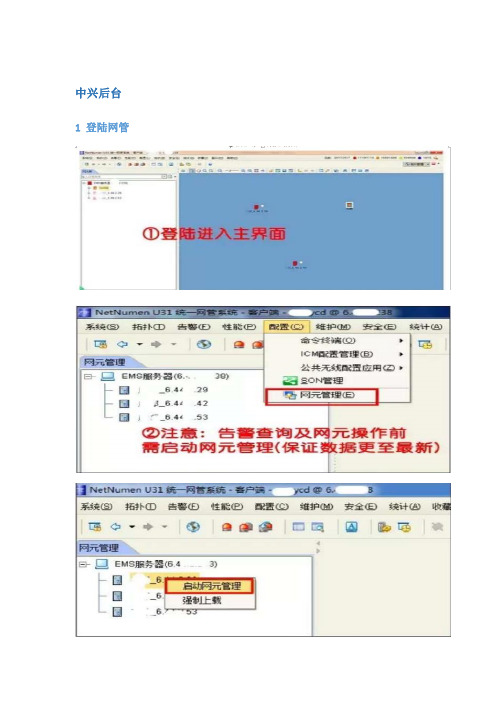
中兴后台1 登陆网管
2告警监控查询
3性能统计
3.1指标提取
4、配置管理
右键启动需要操作的网元
4.1配置数据批量修改(PCI、参考信号功率等快速修改)
4.2 SON管理(ANR/X2等策略的开关及查询)
4.3数据导入导出
4.4 内部邻区配置
4.5外部邻区配置
5、动态管理
6、网元管理—诊断测试
7、系统工具(进行频谱业务信令等跟踪)7.1 信令跟踪(业务跟踪一样)
7.2 频谱扫描
华为后台
1 网管主页面
2 告警查询
3 话统指标提取
4 信令跟踪
4.1 S1标准信令跟踪
4.2 LTE虚拟用户跟踪
4.3 UU 口标准信令跟踪
4.4 RB使用情况跟踪
4.5 以小区吞吐量监控为例
4.6 RSSI统计监控(RSSI 接收信号强度指示)
4.7干扰检测监控
干扰监测通过RRU做数据采集,经主控板对数据作FFT运算分析和处理后,实时显示当前设置频率范围内的信号频谱,实现类似频谱仪的部分功能,方便网上干扰问题的定位、排查和分析。
华为TD-LTE基站网管操作指导书

华为TD-LTE基站网管操作指导书目录1 TD-LTE组网简介 (3)2 LTE网管客户端安装 (3)2.1 LTE网管的安装 (3)2.2 修改HOST文件 (4)3 LTE网管客户端登录 (4)3.1 登陆网管 (4)3.2 主拓扑 (5)4 LTE网管基本的操作 (7)5 LTE网管告警查询及相关处理 (13)5.1 告警查询 (13)5.1.1 活动告警查询 (13)5.1.2 历史告警查询 (15)5.2 根据条件查询 (16)5.3 告警屏蔽 (17)5.4 常见告警级别及相关处理 (17)5.4.1 驻波告警定位及相关处理 (18)5.4.2 射频单元维护异常告警 (19)5.4.3 GPS星卡故障告警 (19)6 LTE命令参考 (20)1 TD-LTE组网简介整个TD-LTE系统由3部分组成,核心网(EPC),接入网(eNodeB),用户设备(UE).EPC又分为三部分:MME 负责信令处理部分,S-GW 负责本地网络用户数据处理部分 P-GW 负责用户数据包与其他网络的处理。
接入网也称E-UTRAN,由eNodeB构成。
eNodeB与EPC之间的接口称为S1接口,eNodeB之间的接口称为X2接口,eNodeB与UE之间的接口称为Uu接口。
2 LTE网管客户端安装2.1 LTE网管的安装系统的安装:OMC920网管系统,则要输入OMC服务器的IP地址,如徐州这边为http://10.40.127.193/cau/,然后下载安装;2.2 修改HOST文件OMC920系统网管安装成功后,需要将附件hosts文件复制到C:\WINDOWS\system32\drivers\etc目录下,替换系统自带的hosts文件,否则登录时会出现异常。
3 LTE网管客户端登录3.1 登陆网管登陆网管OMC920客户端。
打开客户端后,显示的是“用户登陆”,需要填写,用户名(xuzhoucp),密码(1qaz@WSX),当多个OMC920客户端登陆时,需点击服务器下拉菜单,增加网元信息。
Moxa OnCell 3120-LTE-1 4G LTE 网关用户指南说明书

P/N: 1802031200010 *1802031200010*OnCell 3120-LTE-1 Quick Installation GuideMoxa OnCell SeriesVersion 1.0, October 2019Technical Support Contact Information/supportMoxa Americas:Toll-free: 1-888-669-2872 Tel: 1-714-528-6777 Fax: 1-714-528-6778 Moxa China (Shanghai office): Toll-free: 800-820-5036 Tel: +86-21-5258-9955 Fax: +86-21-5258-5505 Moxa Europe:Tel: +49-89-3 70 03 99-0 Fax: +49-89-3 70 03 99-99 Moxa Asia-Pacific:Tel: +886-2-8919-1230 Fax: +886-2-8919-1231 Moxa India:Tel: +91-80-4172-9088 Fax: +91-80-4132-10452019 Moxa Inc. All rights reserved.OverviewThe OnCell 3120-LTE-1 is a reliable, secure, LTE gateway with a state-of-the-art global LTE module. This 4G cellular gateway provides a more reliable connection to your Ethernet network for cellular applications. The OnCell 3120-LTE-1 is ideal for remote-access applications where power consumption needs to be well managed. The power-saving functions, which include power scheduling, allow you to manage the power consumption in your cellular network. Wide-temperature support coupled with high-level EMS protection give the OnCell 3120-LTE-1 the highest level of device stability for any rugged environment. In addition, dual-SIM and GuaranLink support help provide network redundancy to ensure uninterrupted connectivity.The OnCell 3120-LTE-1 also comes with a 3-in-1 serial port for serial-over-LTE cellular network communication, making it suitable for collecting and exchanging data with serial/Ethernet devices. Package ChecklistBefore installing your OnCell 3120-LTE-1, verify that the package contains the following items. If any of these items is missing or damaged, please contact your customer service representative for assistance.• 1 OnCell 3120-LTE-1 unit• 1 DIN-rail mounting kit• 1 console cable•Quick installation guide (printed)•Warranty cardInstallation and ConfigurationYou will need access to a notebook computer or PC equipped with an Ethernet port. The OnCell 3120-LTE-1 has a default IP address that you must use when connecting to the device for the first time.Take the following steps to configure your OnCell 3120-LTE-1. Refer to the Panel Layout of the OnCell 3120-LTE-1 section below for the location of the ports and sockets.Step 1: Insert a SIM card and turn on the OnCell 3120-LTE-1 e a screwdriver to loosen the screws and remove the SIM cardcover located on the top panel of the OnCell 3120-LTE-1.2.Insert one or two 4G SIM cards (nano SIM) into the SIM cardslot(s).If you are only using one SIM card, insert it in the top slot (slot 1;the card in slot 1 is referred to as SIM1).By default, the SIM card in slot 1 is treated as the primary card.To change the default to SIM2 (the card in slot 2), log in to theOnCell’s web UI, and configure SIM2 as the primary card. Whenthe OnCell device is turned on, it boots up based on theconfiguration information stored on the primary SIM card.3.Turn on the OnCell 3120-LTE-1 by connecting a power terminalblock to a DC power source (9 to 36 VDC). For details, refer to the Connecting the Power Input section.4.Reattach the cover.Step 2: Connect the OnCell 3120-LTE-1 to a notebook or PC Since the OnCell 3120-LTE-1 supports MDI/MDI-X auto-sensing, you can use either a straight-through cable or crossover cable to connect the OnCell 3120-LTE-1 to a computer. See the 10/100BaseT(X) Ethernet Port Connection section below for detailed instructions. If the LAN LED indicator on the OnCell 3120-LTE-1 lights up, it means a connection has been established.Step 3: Set up an IP address for the computerSet an IP address on the same subnet as the OnCell 3120-LTE-1. Since the OnCell 3120-LTE-1’s default IP address is 192.168.127.254, and the subnet mask is 255.255.255.0, you should set the IP address of the computer to 192.168.127.xxx and the subnet mask to255.255.255.0.Step 4: Use the web-based manager to configure the OnCell 3120-LTE-1Open your computer’s web browser and typehttp://192.168.127.254 in the address field to access the homepage of the web-based management system. Before the homepage opens, you will need to enter the username and password. For first-time configuration, enter the default username and password given below: Username: adminPassword: moxaClick on the Login button.NOTE You must click the Save Configuration and then the Restart buttons for the configuration changes to take effect.Panel Layout of the OnCell 3120-LTE-11. SIM card holders (SIM1/SIM2)2. 2x2 MIMO cellular antenna port3. 10/100 Base-T(X) Ethernet port 1 (RJ45)4. 10/100 Base-T(X) Ethernet port 2 (RJ45)5. USB port6. DB9 serial port7. LED display8. Reset button9. Console port (reserved for engineering use)10. Grounding screw (M3)11. Terminal block (V+, V-, GND) 12. LED display13. DIN-rail mounting kitDevice DimensionsDIN-rail MountingThe OnCell 3120-LTE-1 Series comes with a DIN-rail kit attached to the back panel. Mount the OnCell 3120-LTE-1 Series on corrosion-free mounting rails that meet the EN 60715 standard.InstallationSTEP 1: Insert the upper lip of the DIN rail into the top hook of the DIN-rail mounting kit.STEP 2: Press the OnCell 3120-LTE-1 Series towards the DIN rail until it snaps into place.To remove the OnCell 3120-LTE-1 from the DIN rail, pull down the lever at the bottom of the DIN-rail kit.Wall Mounting (optional)For some applications, it may be more convenient to mount the OnCell 3120-LTE-1 to a wall, as illustrated below:STEP 1:Remove the aluminumDIN-rail attachment platefrom the OnCell 3120-LTE-1, and then attachthe wall-mounting plateswith M3 screws, as shownin the adjacent diagram.STEP 2:Mounting the OnCell 3120-LTE-1 to a wall requires 4screws. Use the OnCell 3120-LTE-1 device, with wallmount plates attached as a guide, to mark thecorrect locations of the 4 screws. The heads of thescrews should be less than 6.0 mm in diameter, andthe shafts should be less than 3.5 mm in diameter,as shown in the figure at the right.NOTE Test the screw head and shank size by inserting the screws into one of the keyhole shaped apertures of the wall-mountingplates before attaching the plates to the wall.STEP 3:Once the screws are fixed intothe wall, insert the four screwheads through the large openingof the keyhole-shaped aperturesof the mounting kit, and thenslide the OnCell 3120-LTE-1downwards. Tighten the fourscrews for added stability.Wiring RequirementsRead and Follow These Guidelines•Use separate paths to route wiring for power and devices. If power wiring and device wiring paths must cross, make sure the wires are perpendicular at the intersection point.NOTE Do not run signal or communications wiring and power wiring in the same wire conduit. To avoid interference, wires withdifferent signal characteristics should be routed separately. •You can use the type of signal transmitted through a wire to determine which wires should be kept separate. The rule of thumb is that wiring with similar electrical characteristics can be bundled together.•Keep input wiring and output wiring separate.•It is strongly advised that you label wiring to all devices in the system when necessary.Grounding the Moxa OnCell 3120-LTE-1Grounding and wire routing help limit the effects of noise due toelectromagnetic interference (EMI). Run the ground connection from the ground screw to the grounding surface prior to connecting devices. The minimum cross-sectional area of the grounding conductor should be equal to that of the input cable.SIM Card SocketThe OnCell 3120-LTE-1 comes with two nano-SIM card sockets for cellular communication. The nano-SIM card sockets are located on the top panel along with the antenna connectors. Loosen the screws and the remove the cover to access the SIM-card sockets, and then insert the nano-SIM cards into the sockets directly. You will hear a click when the cards are in place. The left socket is for SIM 1 and the right socket is for SIM 2. To remove the cards, push the cards in before releasing them.Connecting the Power InputPinouts for the Power InputsPin NameUsage1 V1+DC PowerInput 1 2V1-DC PowerInput 23GND GroundWiring the Power InputTop and front views of the terminal block connector are shown below:STEP 1: Insert the negative/positive DC wires into the V-/V+ terminals, and the ground wire into the GND terminal.STEP 2: To keep the DC wires from pulling loose, use a small flat-blade screwdriver to tighten the wire-clamp screws on the front of the terminal block connector.STEP 3: Insert the plastic terminal block connector prongs into the terminal blockreceptor, which is located on the bottom panel of the OnCell 3120-LTE-1.Communication Connections10/100Base-T(X) Ethernet Port ConnectionThe 10/100Base-T(X) ports located on the front panel of the OnCell 3120-LTE-1 are used to connect to Ethernet-enabled devices. Pinouts for both MDI (NIC-type) ports and MDI-X (HUB/Switch-type) ports are shown below:MDI Port Pinouts MDI-X Port Pinouts8-pin RJ45PinSignalPin Signal1 Tx+ 1 Rx+2 Tx- 2 Rx-3 Rx+ 3 Tx+ 6 Rx-6 Tx-Serial DB9 ConnectionThe OnCell 3120-LTE-1 has one DB9 male port that supports RS-232,RS-485-4W, RS-485-2W, and RS-422. The pin assignments are shown in the table below:DB9 Male ConnectorPin RS-232 RS-422/485-4w RS-485-2w1 DCD TxD-(A) –2 RxD TxD+(B) –3 TxD RxD+(B) Data+(B)4 DTR RxD-(A) Data-(A)5 GND GND GND6 DSR – –7 TRS – –8 CTS – –9 – – –Console PortThe console port is an RS-232 port that you can connect to with a 4-pinpin header cable (in the package). You can use this port for debugging or firmware upgrades.Pin Signal 1 GND 2NC 3 RxD 4TxDUSBThe OnCell 3120-LTE-1 is provided with a type-A USB 2.0 port, which can be used to connect USB storage device or other type-A USB compatible devices.LED IndicatorsLED indicators are provided on the side panel of the OnCell 3120-LTE-1. The function of each LED is described in the table below: LED Color Behavior FunctionSYS (2 LEDs)Green Power On: System startup is complete and the system is in operation.Off No power is supplied to theOnCell device.Green 1.Blinking at 1-sec intervals 2.Blinking at 2-sec intervals 3. Blinking at 0.5- sec intervals 4. Blinking at 5-sec intervals 1. The OnCell device has beenlocated by the Wireless Search Utility.2. The ABC-02-USB device connected to OnCell device has been detected.3. Importing or exporting files from/to the ABC-02-USB device.4. The OnCell device is in power saving mode.Red 1. Steady On 2. Blinking at 1-sec intervals 1. System error or failure to getan IP address for the device.2. Load/save to the ABC-02-USB device failed.LAN 1/2 Green10/100 Mbps Ethernet mode.LED Color Behavior Function (4 LEDs) Off Not active.Serial (2 LEDs) Green Transmitting or receiving data. Off Not active. LTE (1 LED)GreenLTE is connected.Green Blinking at 0.5-sec intervals UMTS/HSPA/GSM/GPRS/EDGE isconnected.OffNo cellular connection.Signal (3 LEDs)GreenSignal Strength*Cellular RSSI RSSI Range (dBm)Comment1-2 0 < SNR ≤ 12 113 < RSSI ≤ -89Marginal 3-4 12 < SNR ≤ 21 -89 < RSSI ≤ -73Good 5-622 < SNR ≤ 31-73 < RSSI ≤ -51Excellent *Each signal LED is equivalent to a signal strength of 2 levels.NOTE The LTE LED is designated for the cellular connectivity standard and the SIGNAL LED indicates the cellular signal strength.SpecificationsInput Current 0.8 A (max.) Input Voltage9 to 36 VDC Power Consumption 5 W (typ.)Operating Temperature Standard Models: 0 to 55°C (32 to 131°F)Wide Temp. Models: -30 to 70°C (-22 to 158°F) StorageTemperature -40 to 85°C (-40 to 185°F)ATEX / IECEx Zone 2 Certification Information.1.ATEX Certificate Number: DEMKO 18 ATEX 2120XIECEx Certificate Number: IECEx UL 18.0113X2.Ambient Range:-30°C ≤ Ta≤ +70°C, or -30°C ≤ Tamb≤ +70°C3.Certification String : Ex nA IIC T4 GcRated Cable Temp ≧ 90 °C4.Standards Covered:EN 60079-0:2012+A11:2013EN 60079-15:2010IEC 60079-0, 6th Edition (2011-06) + Corr. 1 (2012-01) + Corr. 2 (2013-12) + I-SH 01 (2013-11) + I-SH 02 (2014-10), IEC 60079-15, 4th Edition (2010-01) + I-SH 01 (2016-09)5.Conditions for Safe Usage:These devices shall be mounted in a suitable tool-accessibleATEX/IECEx certified enclosure rated at least IP54 as defined inEN/IEC 60529, Pollution Degree 2 and EN/IEC 60664-1, and shall be used within their rated electrical and environmental ratings. Grounding-wire SizeThe minimum cross-sectional area of the grounding conductor should be equal to that of the input cable.Moxa Inc.4th Floor, No.135, Lane 235, Baoqiao Rd. Xindian Dist., New Taipei City, Taiwan。
中兴LTE网管操作指导书(最全)
精品文档
校准 RET
初次创建 AISG 设备,天线芯片中存储的是厂家设置的默认下倾角(12° /2°)。应先进行校准,再执行查询及设置 RET 倾角等操作。如果安装时,手 动调整了天线倾角,通过 RET 不能查询到天线实际的倾角。所以开局时,一般 要校准 RET,然后通过 OMC/LMT 做设置倾角等其它操作。 1. 在上方的搜索栏中,输入关键词“RET”,即可筛选出有关 RET 的命令。
灌包测试步骤.docx 16欢。迎下载
精品文档
PS 数据速率
17欢。迎下载
精品文档
创建小区级测量事件:
以创建小区级 A4 事件为例: 第一步:
第二步:对应 A4 参数修改好
18欢。迎下载
精品文档
第三步:添加一条索引集
第四步:
19欢。迎下载
精品文档
X2 功能开通步骤
LTE SON X2功能商用部署指导书(V3.20.30)_1R1.01.docx
2欢迎。下载
精品文档
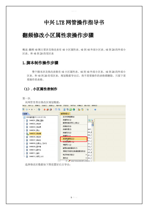
(2).4G-4G 外部小区表修改
基站与小区之间加邻区之前需要添加外部小区,小区属性表变了,对应的外部小区也需 要跟着一起修改。外部小区表的修改直接使用修改小区属性表使用的规划数据,找到外部小 区表,把对应的小区按照翻频方案一一修改:
(3).4G-2G 外部小区表修改
4G 到 2G 外部小区表和 4G 到 2G 的邻区修改异于 4G 外部小区表修改,4G-2G 外部小区或邻区 修改时需要将原有的外部小区和邻区先删除,接下来才是按照新的 LAC 和 CI 在原有的邻区 关系上继承添加,即脚本需按删除和添加顺序制作
图 0-10 设置电调下倾角数值
3. 点击[确定]按钮,进行 RET 的倾角设置。在操作结果列表中,“操作结 果”为成功代表天线电调的下倾角已设置成功,如图 0-11 所示。
中兴LTE网管操作
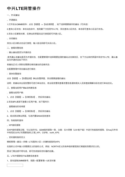
中兴LTE⽹管操作⼀、开/闭基站、开通基站1.打开后台OMMB软件:点击【视图】->【动态管理】,如下选择需要操作的基站(可多选)2.查询⼩区状态:单击动态命令,拖到最下⽅找到TD-LTE,双击查询⼩区状态,单击即可查询⼩区运⾏状态。
3.双击⼩区解除关断,在弹出的界⾯击运⾏按钮即可开通⼩区。
、关闭基站双击⼩区关断点击运⾏按钮,输⼊验证码即可关闭⼩区。
⼆、查看告警信息:确认基站是否为开通状态.⾸先确认该基站是否为开通状态,在配置管理中选择需要监测的基站点击修改区,在下⽅出来的界⾯中双击TD-LTE,确认基站为开通状态如下所⽰:若基站正式⼊⽹则在需要在修改基站的运维状态:在配置管理中双击基站进⾏修改::具体告警查询点击【视图】->【告警监视】弹出告警界⾯,双击需要查看的基站:说明:若基站未出现告警则可进⾏单站优化,若出现告警则查看告警信息通知相关⼈员排查故障解决后在进⾏单站优化。
三、查看当前⽤户数&经纬度信息.查看当前⽤户数:1、点击【视图】->【诊断测试】,然后双击基站:2.双击BPL板即可查看⼩区⽤户数,如下图所⽰:.查看基站的经纬度1、点击【视图】->【诊断测试】,然后双击基站2、组合测试弹出界⾯,勾选内置GNSS信息查询四、性能指标查询、KPI指标提取在KPI指标提取过程,与以往的TD、GSM指标提取⼀致,注意:在⼤⽹管(U31客户端)中进⾏性能指标提取,在hxsj⽂件夹中有现在台州LTE需要指标(⼯程_KPI、CSFB、north_KPI)、定时器和指标定义模板管理—基站—多模—LTE服务⼩区—关键性能指标(KPI)在指标公式中输⼊你需要定义的指标公式,例如:NORTH定义的各种指标都是我们根据实际需求定义的。
预设门限全部不⽤勾选,即可完成指标定时器的创建。
五、LTE中跟踪信令&调度信息查询1、⾸先登陆OMMB账号,视图—配置管理—UE定时器2、视图中统⼀数据跟踪:3、登陆超级账号:⽤户名:USER(⼤写),密码:SUPER(⼤写)4、统⼀数据跟踪:输⼊你需要跟踪的站号或者站名5、跟踪对象选择UE级⼩区(切记);跟踪对象中选择跟踪类型接⼝(UU、S1、X2)6、频谱扫描,进⼊超级⽤户后会显⽰如下界⾯:(即为⼲扰)7、MTS中信令跟踪:在观察对象中只需要勾上MTS即可;(实际根据需要,你可以选择跟踪下⾏,也可以选择跟踪上⾏)六、异频邻区配置以台州移动枢纽楼室分(站号19919)与台州移动枢纽⼤楼宏站(站号405899)之间添加异频邻区,并开启异频切换为例,按操作顺序介绍如何配置异频邻区和切换参数。
LTE网管常用操作总结(网优)
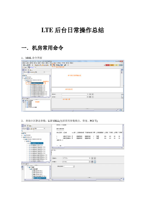
LTE后台日常操作总结一.机房常用命令1、MML命令界面2、查询小区静态参数:LST CELL(包括常用参数频点、带宽、PCI等)3、查询小区动态参数DSP CELL4、修改小区MOD CELL5、查询PDSCH配置信息(参考信号功率):LST PDSCHCFG 单位0.1毫瓦分贝6、修改PDSCH配置信息(参考信号功率) MOD PDSCHCFG7、查询活动告警:LST ALMAF(历史告警LST ALMLOG)8、查询小区下所有实时在线用户数的基本信息:DSP ALLUEBASICINFO二.信令跟踪1、信令跟踪2、S1标准信令跟踪3、Uu口标准信令跟踪4、RSSI统计监控(RSSI 接收信号强度指示)5、干扰检测监控干扰监测通过RRU做数据采集,经主控板对数据作FFT运算分析和处理后,实时显示当前设置频率范围内的信号频谱,实现类似频谱仪的部分功能,方便网上干扰问题的定位、排查和分析。
6、总吞吐量监控该任务监测用户的保证比特速率GBR(Guaranteed Bit Rate)及非保证速率对应数据无线承载的吞吐量,用以评估当前空口情况及调度算法。
三.指标监控1、L TE系统KPI指标查询四.告警查询1、当前告警浏览选择菜单——监控——浏览当前告警2、查询告警日志选择菜单——监控——查询告警日志五.e NodeB邻区操作由于LTE系统的扁平架构,相对2、3G减少了BSC、RNC,导致每个eNodeB都要维护一套邻区关系。
1、本站邻区添加本站邻区直接添加:ADD EUTRANINTRAFREONCELL2、增加系统内同频eNodeB邻区系统内同频eNodeB间小区邻区关系的建立,需要先创建EUTRAN外部小区关系在MML命令行输入:ADD EUTRANEXTERNALCELL注意:EUTRAN外部小区信息一定要正确,基站通过增加这些信息来维护邻区关系,如果小区信息有错误,会导致切换失败。
创建完外部小区关系后,开始增加EUTRAN同频邻区关系,在MML命令行输入:ADD EUTRANINTRAFREQNCELL3、查询系统内同频eNodeB邻区在MML命令行输入:LST EUTRANEXTERNALCELL注意:什么都不填表示查询所有EUTRAN外部小区信息。
中兴LTE网管操作指导手册
1.勾选需要操作的网元,在[AISG设备]命令组中,双击「AISG2.0批量查询天线设备数据」命令,AISG协议2.0和1.1版本是分开的,如所示。
图-双击『AISG2.0批量查询天线设备数据』命令. 选择AISG设备,点击「运行」按钮,弹出[选择AISG设备数据域]对话框,选择需要查询的信息。
根据需要将公共参数和电调天线参数中的相应项勾选上,但是一般情况下只需要选择电调天线参数的前4项,如和所示。
图-[选择AISG设备数据域]对话框图-选择电调天线参数的前4项. 点击[确定]按钮,开始查询AISG设备数据,当查询完成后,在操作执行详细信息栏中,可以看到AISG设备数据,包括:天线型号、频带等信息,如所示。
图-查询结果校准RET初次创建AISG设备,天线芯片中存储的是厂家设置的默认下倾角(12°/2°)。
应先进行校准,再执行查询及设置RET倾角等操作。
如果安装时,手动调整了天线倾角,通过RET不能查询到天线实际的倾角。
所以开局时,一般要校准RET,然后通过OMC/LMT做设置倾角等其它操作。
. 在上方的搜索栏中,输入关键词“RET”,即可筛选出有关RET的命令。
在[AISG 设备]命令组中,双击「校准RET」命令,如所示。
图-双击「RET校准」命令. 点击「运行」按钮,出现以下操作结果界面,如所示。
提示:当操作结果显示成功,代表电调可以校准,在这种情况下设置电调下倾角一般不会有问题。
图-RET校准结果设置RET倾角. 在[AISG设备]命令组中,双击「设置RET倾角」命令,如所示。
图-双击「设置RET倾角」命令. 点击「运行」按钮,弹出[设置]对话框框,将『倾角(度)』的属性值输入为“需要设置的电调下倾角数值”,如所示。
图-设置电调下倾角数值. 点击[确定]按钮,进行RET的倾角设置。
在操作结果列表中,“操作结果”为成功代表天线电调的下倾角已设置成功,如所示。
图-设置下倾角结果查询RET倾角. 在[AISG设备]命令组中,双击「查询RET倾角」命令,然后点击「运行」按钮,在在操作结果列表中,显示查询的RET倾角度数,如所示。
中兴LTE网管操作指导4.doc

中兴LTE网管操作指导4中兴网管操作指导一:账号登陆输入账号密码信息后请选择所要登陆地市的IP地址,具体操作如下图所示:IP地址添加若无所需登陆的地市IP,需自行添加新的IP地址,添加新的地市IP地址操作如下图所示:广东中兴片区各地市网管IP地址登陆成功后进去网管操作界面如下图:二.指标查询操作点击性能—>查询模板管理,操作如图所示:进入查询模板管理后,界面如下:查询模板选择选择需要的模板后右键按模板查询,操作如图:进入模板后界面如下:在逻辑过滤选项可以设置门限,使指标只输出低于或高于门限的小区:查询对象说明查询指标需对汇总对象与通配层次进行选择:汇总对象有4个选择项具体如下:所有位置汇总成一条(所有已选择的网元在设置后的时间粒度汇总成一条指标)汇总到“子网”(所有已选择的网元在设置后的时间粒度每个子网一条指标)汇总到“网元”(所有已选择的网元在设置后的时间粒度每个基站一条指标)汇总到“小区”(所有已选择的网元在设置后的时间粒度每个小区一条指标)。
中兴LTE网管常用操作概述(全面)4LTE网管U31使用说明:登陆客户端进入拓扑界面1:告警监控查询点击按钮,可以查询当前的告警;点击网元树,可以搜网管中某一个小区的所有历史告警和当前告警;点击可打开批量站点查询当前告警或历史告警如:双击一个故障站点可观察该站机架组(故障RRU位置,故障板件位置):双击一条故障信息或者一个故障RRU或板件可获取具体故障解释:2:性能统计:(导出日报/TOP5等报表)如图打开如下:现有模板指标提取:分别选择所需的指标,查询的站点和查询时间粒度:收周记的时候,只有两个学生谈到了这个问题,他俩学习都比较好,而现在的座位不是很理想,他们都说按照成绩安排座位是个不错的方法,可以激发学生的学习的热情,调动学生的学习积极性,其中一个学生还说,他现在正在为取得选择座位的优先权而不懈努力。
这样的结果,正符合我的想法,于是我又对同学们说:“关于按照成绩安排座位的这件事情,有些同学已经发表了自己的意见,目前看来是百分之百的学生表示同意。
- 1、下载文档前请自行甄别文档内容的完整性,平台不提供额外的编辑、内容补充、找答案等附加服务。
- 2、"仅部分预览"的文档,不可在线预览部分如存在完整性等问题,可反馈申请退款(可完整预览的文档不适用该条件!)。
- 3、如文档侵犯您的权益,请联系客服反馈,我们会尽快为您处理(人工客服工作时间:9:00-18:30)。
LTE网关使用说明
一、开机前的准备
机身侧面的按键说明:
1、WPS:WiFi保护设置,用于WIFI快速建立加密连接,不自动开启。
2、路由/调试模式按键:往上拨是路由模式,即可用有线和无线连接上网;往下拨是调
试模式,需要配合USB口进行调试。
默认拨到路由模式。
3、电源开关
4、USB口:用于设备调试
5、外接天线接口:由于设备有内置天线,在覆盖范围比较小的情况下可以不外接天线。
6、直流电源插口
7、有线网口
1
2
2
2 3
2 4
5
2
6
2 7
2
机身背面的按键说明:
8、内部/外边天线开关:用来切换内置/外置天线,一般只需拨到inner(内部)即可。
9、USIM卡插槽
8
2
9
2
开机前只需插入USIM卡,把按键2拨到路由模式,把电源打开即可。
二、开机后一般配置
1、设备通电后,可以选择有线或者无线连接,在此以无线连接为例:
可以搜到类似以下的信号,开放模式,自动获取地址即可。
2、用浏览器进入设备的地址192.168.0.1进行一般的配置,用户名和密码都是admin。
进去之后,采用默认配置即可。
如需改动无线设置,例如SSID、无线加密、无线模式、信道等,则进入“无线网络配置”→“基本配置”/“安全配置”进行设置即可。
3、查看联网状态
插入USIM卡后,设备会自动联网,可通过“联网状态”→“联网状态”查询当然的网络情况。
联网状态下的默认配置是3G和4G双模(LTE优先),也可以手动按需更改接入的模式。
一般采用默认即可。
接入前,请先确认现场是否有LTE信号,以及USIM卡的状态正常,
如能成功接入,LTE连接状态会是connected。
这样用户端就可以接通外网上网。