学习资料欧姆龙E3X-HD光纤放大器调试SOP.doc
欧姆龙 E3X-HD 使用说明书

UP/DOWN1-32-22-31-11-2 L/D1pnt full*2192185-2B-1--2-4-14-3rstMODEMODEyesrstrst userMODEUP/DOWNUP/DOWNUP/DOWN4-2L/DMODEUP/DOWNMODEUP/DOWNMODEUP/DOWNMODE12345MODE UP/DOWNUP/DOWNMODE30003500 L/DL/D100 9999 999920008000-3--4--1--2-Incident light level setting: The larger incident level of the Step 1 and 2 values is adjusted to the power tuning level.Threshold setting: Set to the middle between the Step 1 and 2 incident light levels.PRECAUTIONS ON SAFETYPRECAUTIONS FOR SAFE USEPRECAUTIONS FOR CORRECT USEChecking the Package ContentINSTRUCTION SHEETPRECAUTIONSIndicates a potentially hazardous situation which, if not avoided, may result in minor or moderate injury or in property damage.• Amplifier Unit: 1 • Instruction Sheet (this sheet): 1 (Japanese, English and Chinese)Do not use the product with voltage in excess of the rated voltage.Never use the product with an AC power supply. Otherwise, ■ Mounting on DIN TrackLet the hook on the Amplifier Unit's Fiber Unitconnection side catch the track and push the unit until it clicks.■ Removing from DIN TrackPush the unit in the direction 1.■ Mounting Ampli er Units in Group (Wire-saving Connector Type Models)■ Use Fiber CutterInsert a Fiber Unit into a fiber cutter hole.Press down the blade at a singlestroke to cut the Fiber Unit.■ Mount Fiber UnitOpen the protective cover.Raise the lock lever.Insert the Fiber Unit in the fiberunit hole to the bottom.Return the lock lever to the originalposition and fix the Fiber Unit.Through-beam: Workpiece is present1.DIN track and push them until they click.Single Core Multi Core1.1.1.1.1.2.3.4.2.3.Slide the Ampli er Units in the direction 2.2. 1.2.WorkpieceWorkpiecePower Supply Connecting TerminalSetting is CompletedWhen mounting a coaxial reflective Fiber Unit, insert the single-core Fiber Unit to the upper hole (Emitter side) and the multi-core Fiber Unit to the lower hole (Receiver side).1-3Mounting Fiber Unit2-2Switching Control OutputSmart Tuning [Easy Sensitivity Setting]2-31-1DimensionsL/D1.Release the button when [ ] is displayed.The red digital display changes .Incident light level setting: The incident level in Step 1 is adjusted to "0".Threshold setting: The value is set to approx. 7% of the incident light level of 1. If the incident light level of 1 is smaller during long distance detection, the minimum value by which an output is correctly turned ON will be set.Lift it up in the direction 2.2.Step 1 and Step 2 can be reversed.the slave Amplifier Units.Insert a standard Fiber Unit up to the position in which it is cut; and a thin-diameter Fiber Unit to the bottom of the hole.from separating due to vibration or other cause.4.Re ective: Set to "Light ON" to turn theoutput ON with a workpiece in the detection area.[L/D Indicator] turns ON.Through-beam: Set to "Dark ON" to turn the output ON with a workpiece in the detection area.[L/D Indicator] turns ON.even with a single amplifier unit.The following precautions must be observed to ensure safe operation of the Sensor.• Do not use the Sensor in environments subject to flammable or explosive gases.• Do not use the Sensor in environments subject to exposure to water, oil, chemicals, etc.• Do not install the Sensor in environments subject to intense electric field or ferromagnetic field.• Do not attempt to disassemble, repair, or modify the Sensor Unit in any way.• Do not apply voltages or currents that exceed the rated ranges.• Do not use the Sensor in any atmosphere or environment that exceeds the ratings.• Do not miswire such as the polarity of the power supply.• Connect the load correctly.• Do not short both ends of the load.• Do not use the Sensor if the case is damaged.• When disposing of the Sensor,treat it as industrial waste.• Burn injury may occur. The Sensor surface temperature rises depending on application conditions, such as the ambient temperature and the power supply voltage. Use caution when operating or cleaning the Sensor.• High-Voltage lines and power lines must be wired separately from this product. Wiring them together or placing them in the same duct may cause induction, resulting in malfunction or damage.• When setting the Sensor, be sure to check safety such as by stopping the equipment.(1) Locations subject to direct sunlight(2) Locations subject to condensation due to high humidity (3) Locations subject to corrosive gas(4) Locations subject to vibration or mechanical shocks exceeding the rated values • Use an extension cable with a minimum thickness of 0.3 mm 2 and less than 100 m long.• Do not apply the forces on the cord exceeding the following limits:Pull: 40N; torque: 0.1N·m; pressure: 20N; bending: 3 kg• The Sensor is ready to operate 200 ms after the power supply is turned ON. If the Sensor and load are connected to power supplies separately, turn ON the power supply to the Sensor first.• When using a Wire-saving connector type product, place a protective label (provided with the E3X-CN series connectors) on the power supply connecting terminals that are not used, to prevent electric shock or short circuit.• Output pulses may occur when the power supply is turned OFF. Turn OFF the power supply to the load or load line first.• Excessive incident light cannot be sufficiently handled by the mutual interference prevention function and may cause malfunction. To prevent this, set a higher threshold level.• Make sure that the power supply is turned OFF before connecting, separating or adding Amplifier Units.• Do not pull or apply excessive pressure or force (exceeding 9.8N) on the Fiber Unit when it is mounted on the Amplifier Unit.• The E3X-MC11-SV2 and E3X-MC11-S Mobile Consoles cannot be used.• Mutual interference prevention does not function among the E3X-DA-N/SD/NA amplifiers. It functions among E3X-DA-S/MDA models.• The E3X-DRT21-S, E3X-CRT and E3X-ECT Communication Units cannot be used.• Always keep the protective cover in place when using the Amplifier Unit.• Dor not use thinner, benzine, acetone, and lamp oil for cleaning.Incident light level setting: Adjust the max. incident light level on Step 1 as the power tuning level.Threshold setting: Set to the middle between max. and min. incident light levels on Step 1.Incident light level setting: The Step 2 incident level is adjusted to half the power tuning level.Incident light level setting: The Step 2 incident light level is adjusted to the power tuning level.Threshold setting: Set to the value obtained by [Incident Level at Step 2 x Percentage Tuning Level + Incident Level at Step 2].Percentage TuningSmart Tuning ErrorPress button to adjust the threshold level.1.2.1.2.1.UP/DOWNSetting is CompletedThe red digital display changes .Refer to " Detailed Settings".Hold the key for high-speed level adjustment.No Smart Tuning other than Power Tuning can be used if Percentage Tuning is set.Threshold setting: Set to the same value as the Step 2 incident level.through while [ ] -> [ ] -> [ ] is displayed in red digital.seconds or longer until [ ] is displayed in red digital. After the workpiece passes 1.*2192185-2ModelNPN OutputPNP OutputE3X-HD11E3X-HD41Number of Control OutputsConnection MethodLight Source (Wavelength)Power Supply VoltagePower ConsumptionControl OutputProtection CircuitsAmbient IlluminationAmbient Temperature RangeAmbient Humidity RangeInsulation ResistanceDielectric StrengthVibration ResistanceShock ResistanceMaterialPre-wired TypeE3X-HD14E3X-HD44M8 Connector TypeWire-saving Connector Type*1Red 4-element LED (625 nm)12 to 24 VDC ±10%, ripple (p-p) 10% max.Possible for up to 10 units *2Case: Heat resistant ABS (ABS) / Cover: Polycarbonate (PC)E3X-HD6E3X-HD8EnableKey Lock FunctionZero Reset FunctionRatings and Speci cations4-3Normal: 720 mW max. (current consumption: 30 mA max. at powersupply voltage of 24 VDC; 60 mA max. at power supply voltage of 12 VDC)Power supply reverse polarity protection, output short-circuit protection andoutput reverse polarity protectionMutual Interference PreventionOperating and storage: 35% to 85% (with no condensation)20 MΩ min. (at 500 VDC megger)1,000 VAC at 50/60 Hz for 1 minuteReceiver side: Incandescent lamp: 20,000 lux max. / Sunlight: 30,000 lux max.Power-saving ECO: 530 mW max. (current consumption: 22 mA max. at powersupply voltage of 24 VDC; 44 mA max. at power supply voltage of 12 VDC)Load power supply voltage: 26.4 VDC; NPN/PNP open collector;load current: 50 mA max.; residual voltage: 2 V max.L/Dbutton for 3 seconds or longer.button when a timer menu (other display than"----") is displayed. Use button to set thetime. (1 to 9999ms in 1 ms steps; the initial value: 10 ms)Press button in [ ] menu, then usebutton to set the percentage tuning level.(-99% to 99% in 1% steps; the initial value: -10%)Disables all button operations. [ ] is displayed when the button is pressed.Changes the incident light level to "0". The threshold level is also shifted accordingly.Select [ ] in and press button.Select [ ] in and press button.MODEMODEUP/DOWNUP/DOWNApprox. 65 g Approx. 20 g Approx. 22 gInput/Output Circuit Diagram4-2CancelWeight (Main Unit Only)Maximum connectable unitsItemThreshold ValueControl OutputInitial Value55L-on* Settings for other functions are returned tothe detailed setting initial values.Hold button for 3 seconds or longer to enter SET mode.MODESET mode provides the function settings described hereafter. The initial display shownafter transition from one function to another represents the factory default.Differential Setting Response Time12345250 μs500 μs1 ms10 ms100 msUP/DOWNUP/DOWNUse button to specify the response time.Detects if the absolute value of the incident light levelchange of the set response time is larger than thethreshold value. The display shows the change of theincident light level of the set response time in red.Smart Tuning is canceled if the detection modeis changed.*The communication and mutual interferenceprevention functions are disabled when thedetection mode is set to Super High-speed Mode.Changing the Target Incident Light Level(Power Tuning Level)Detecting Transparent or Small WorkpieceDetecting Incident Light Level ChangeFunction Setting DescriptionFunction Setting DescriptionChanging Functions to Set in SET Mode[ ]: Functions 1. to 5. can be set.[ ]: Functions 1. to 10. can be set.Stable Detection Regardless of Incident LightLevel ChangeAPC (Auto Power Control)Always ON16 unitsMODEUP/DOWN10 to 55 Hz with a 1.5-mm double amplitude for 2 hours each in X, Y and Z directions500 m/s2, for 3 times each in X, Y and Z directionsUse button to set the power tuning level.[100 to 9999 in 1 steps; the initial value: 9999]Operating: Groups of 1 to 2 Ampli ers: −25°C to 55°CGroups of 3 to 10 Ampli ers: −25°C to 50°CGroups of 11 to 16 Ampli ers: −25°C to 45°CStorage: −30°C to 70°C (with no icing or condensation)Refer to " Convenient Setting Features"Refer to " Convenient Setting Features"Refer to "2-3 Smart Tuning"The incident light level in setting mode is areference value. It may be changed whenswitched to detection mode.When the differential function is enabled,the detection function setting is disabled.Smart tunings except power tuning are disabled.The adjustment range of powr tuning is approx.1 to 1/100 times.*1: Either of E3X-CN11 (Master connector: three core) and E3X-CN12 (Slave connector: single core) can be used.*2: When selecting the inspection function as highest speed mode (SHS), the communications function will bedisabled and mutual interference prevention function and communications function cannot be used.When a power tuned E3X-DA-S is included, up to six units can be connected with the mutual interferenceprevention function enabled. When a power tuned E3X-MDA is included, up to ve units can be connected withthe mutual interference prevention function enabled.-3--4-受光量设定:将1、2中受光量大的一方调整为光量调整等级。
光纤放大器的调节方法

光纤放大器的调节方法本页仅作为文档封面,使用时可以删除This document is for reference only-rar21year.March光纤放大器的调节方法无线光通信是以激光作为信息载体,是一种不需要任何有线信道作为传输媒介的通信方式。
与微波通信相比,无线光通信所使用的激光频率高,方向性强(保密性好),可用的频谱宽,无需申请频率使用许可;与光纤通信相比,无线光通信造价低,施工简便、迅速。
它结合了光纤通信和微波通信的优势,已成为一种新兴的宽带无线接人方式,受到了人们的广泛关注。
但是,恶劣的天气情况,会对无线光通信系统的传播信号产生衰耗作用。
空气中的散射粒子,会使光线在空间、时间和角度上产生不同程度的偏差。
大气中的粒子还可能吸收激光的能量,使信号的功率衰减,在无线光通信系统中光纤通信系统低损耗的传播路径已不复存在。
大气环境多变的客观性无法改变,要获得更好更快的传输效果,对在大气信道传输的光信号就提出了更高的要求,一般地,采用大功率的光信号可以得到更好的传输效果。
随着光纤放大器(EDFA)的迅速发展,稳定可靠的大功率光源将在各种应用中满足无线光通信的要求。
1 、EDFA的原理及结构掺铒光纤放大器(EDFA)具有增益高、噪声低、频带宽、输出功率高、连接损耗低和偏振不敏感等优点,直接对光信号进行放大,无需转换成电信号,能够保证光信号在最小失真情况下得到稳定的功率放大。
、 EDFA的原理在掺铒光纤中注入足够强的泵浦光,就可以将大部分处于基态的Er3+离子抽运到激发态,处于激发态的Er3+离子又迅速无辐射地转移到亚稳态。
由于 Er3+离子在亚稳态能级上寿命较长,因此很容易在亚稳态与基态之间形成粒子数反转。
当信号光子通过掺铒光纤时,与处于亚稳态的Er3+离子相互作用发生受激辐射效应,产生大量与自身完全相同的光子,这时通过掺铒光纤传输的信号光子迅速增多,产生信号放大作用。
Er3+离子处于亚稳态时,除了发生受激辐射和受激吸收以外,还要产生自发辐射(ASE),它造成EDFA的噪声。
E3X-HD

智能光纤放大器
Ӵ ᛳ ఼
E3X-HD
即使是高功能,使用一个手指也能轻松操作。 能够长期稳定检测的光纤放大器
• 一个按钮即可进行最佳设定 配备 “Smart Tuning”
• 追求可用性的设计、任何人都可轻松设定 • 感知脏污及振动·LED常年老化,自动校正受光量·投光量。 • 最高级的压倒性功率下也可稳定检测低反射检测物体和大型检测物体 (配备GIGARAYII)
负载电源电压 DC26.4V以下,集电极开路输出型 (NPN/PNP输出 因型号而异) 负载电流:50mA以下 (残留电压2V以下)、
OFF状态电流0.5mA以下
保护回路
电源逆接保护、输出短路保护、输出逆连接保护
响应时间
高速模式 (SHS) *3
高速模式 (HS) 标准模式 (Stnd)
动作、复位: 动作、复位: 动作、复位:
ห้องสมุดไป่ตู้
䕧ߎᰒ冫
L D DPC ST O U T
䯜ؐ˄㓓˅ ফܝ䞣˄㑶˅
ⓣ⎆Ẕ⌟఼
ѻક䗝ൟ ݅䗮⊼ᛣџ乍
ܝ㑸ऩܗ ܝ㑸Ӵᛳ఼
E3X-HD E3X-ZD E3X-DA-S E3X-DAC-S Ӵᛳ఼⫼ 䗮ֵऩܗ
ݐ乒ᣝ䪂᪡ᗻ䇃᪡䰆ℶᗻ
᠈ⴔ༫䕏ᵒ᪡
䲒ҹ ᣝࡼʽ
ᣝ䪂῾ ᥦ៤ϔᥦ
वԣʽ
᮴⊩᷵ℷᯊ 䮾⚕
DPC
ᯊ䯈
72
䆶⬉䆱 400-820-4535 ᳔ᮄֵᙃ
种类
■ 光纤放大器
标准 【外形尺寸图➜P.78】 形状
连接方式
导线引出型 (2m)
NPN输出 E3X-HD11 2M
ܝ E3X-HD 㑸
传感器产品培训-E3X
简易灵敏度可调式光纤传感器
光纤配置
漫反射:E32-ZD200 对射: E32-ZT200
M4螺钉
M6螺钉
光纤传感器适用场合
特殊需要Βιβλιοθήκη 耐药品、耐腐蚀高温场合
液位检测
色标检测
检测物体有无
微小物体检测
食品行业可清洗
需安装在可动部上
安装空间狭小
透明物体检测
请参考:《传感器综合样本2004》P AB-8
E32-T16P 最小检测物体
Φ0.3
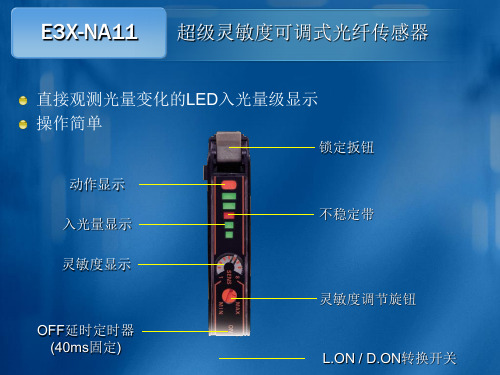
E3X-NA11
超级灵敏度可调式光纤传感器
放大器有防干扰功能,可并排安装
MAX = 5
光量值直观显示 调节方便、效果精准
锁定扳钮
受光量显示
门槛值/功能设定值
操作键
动作指示灯
光量调整指示灯
SET/ RUN
L.ON / D.ON
E3X-DA11-S
数字式光纤传感器
定时器功能
E3X-ZA11
简易灵敏度可调式光纤传感器
调节旋钮
动作指示灯 无光量条
E3X-ZA11
简易灵敏度可调式光纤传感器
适用场合
被检测物体>0.5mm 不能用于超高速的场合 不能用于有延时要求的场合 漫反射距离<120mm、对射距离<300mm 放大器不能紧密排列
E3X-ZA11
数字式光纤传感器的特殊功能
E3X-DA11-S
数字式光纤传感器
标准色标检测
光纤放大器的常规调节方法

光纤放大器的常规调节方法使用漫反射光纤,状态在L.ON1. 将MODE 拨到L.ON2. 通电后,将光纤对到检测物体,红光OUT亮,将旋钮左旋到OUT灯灭,再将旋钮向右以1/4圈的速度旋转到OUT红灯亮,调整完毕。
如需反向动作,做L.ON/D.ON切换使用对射光纤,状态在L.ON1. 将MODE拨到L.ON2. 通电后,将光纤安装好,没有检测物体的情况下,如红灯亮,将旋钮左转到OUT灯灭,再将旋钮向右以1/4圈的速度旋转到OUT红灯亮,调整完毕。
将检测物体放入光纤之间,OUT灯灭。
如需反向动作,做L.ON/D.ON切换光纤放大器工作原理及其在无线光通信的应用0 引言无线光通信是以激光作为信息载体,是一种不需要任何有线信道作为传输媒介的通信方式。
与微波通信相比,无线光通信所使用的激光频率高,方向性强(保密性好),可用的频谱宽,无需申请频率使用许可;与光纤通信相比,无线光通信造价低,施工简便、迅速。
它结合了光纤通信和微波通信的优势,已成为一种新兴的宽带无线接人方式,受到了人们的广泛关注。
但是,恶劣的天气情况,会对无线光通信系统的传播信号产生衰耗作用。
空气中的散射粒子,会使光线在空问、时间和角度上产生不同程度的偏差。
大气中的粒子还可能吸收激光的能量,使信号的功率衰减,在无线光通信系统中光纤通信系统低损耗的传播路径已不复存在。
大气环境多变的客观性无法改变,要获得更好更快的传输效果,对在大气信道传输的光信号就提出了更高的要求,一般地,采用大功率的光信号可以得到更好的传输效果。
随着光纤放大器(EDFA)的迅速发展,稳定可靠的大功率光源将在各种应用中满足无线光通信的要求。
1 EDFA的原理及结构掺铒光纤放大器(EDFA)具有增益高、噪声低、频带宽、输出功率高、连接损耗低和偏振不敏感等优点,直接对光信号进行放大,无需转换成电信号,能够保证光信号在最小失真情况下得到稳定的功率放大。
1.1 EDFA的原理EDFA的泵浦过程需要使用三能级系统,如图1所示。
欧姆龙 E3X-DA□□-S 数字光纤传感器 说明书
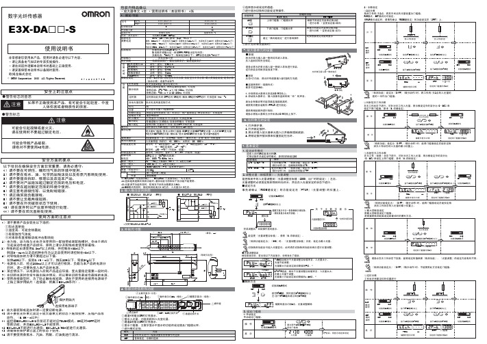
7.基本设定13.9×3=11.732.829.815.1 3.9×3=11.712.152.输入输出段回路图■拆卸压住1方向后,将光纤传感器插入部往2的方向提。
■连接使用时(接插件式)最多可连接16台。
1.分别将放大器单元安装到DIN导轨上。
2.滑动放大器单元,插入接插件直到听到“咔”的声音。
因为会有振动等可能导致连接部脱离时,请使用另售安装配件(PFP-M)进行固定。
请采用相反顺序进行拆卸。
请务必将放大器单元分开后再从DIN导轨上拆下。
1)手动设定能把检测中的入光量调整到「光量调整目标值(2000:出厂时的设定)」左右。
光量调整时必须固定检测物体和光纤头,并且在入光量安定的状态下进行。
辅数字显示中以一条条棒表示模拟条。
(模拟条显示后放开按键。
)■设定方法事先请确认「MODE键设定」的功能设定在「PTUN」(光量调整)的位置上。
选择入光时ON或者遮光时ON。
1.设定动作模式●光量调整错误辅数码显示闪烁2次,光量调整解除能变更「光量调整目标值」。
参照「8.详细设定」。
「检测功能设定为」「SHS」时,「光量调整目标值」无效,设定为最小光量。
切换检测功能会引起入光量变化,此时请在切换检测功能后再次进行光量调整。
2)示教设定 ①2点示教 检测工件有/无2点,将其中间点的光量设置为门槛值。
RUN模式、SET模式均可设定。
用RUN模式设定时,请事先确认「MODE键设定」的功能设定在「2PNT」上。
3.设定门槛值②对射型无工件示教在无工件状态下进行。
可针对无工件入光量,用示教设定中的百分比(0~99%)来③反射型无工件示教在无工件(背景)状态下进行。
可针对无工件入光量,用示教设定中的百分比④最大灵敏度设定 用最大灵敏度设定门槛值。
「检测功能设定为」「DIFF」(微分动作)时,不能使用此方法设定门槛值。
⑤定位示教E3X-DA21-S E3X-DA7-S E3X-DA9-SE3X-DA51-S221ー导线引出式接插件式*1*1:E3X-CN21(母接插件4芯)、E3X-CN22(子接插件2芯)均可使用。
omron光纤放大器E3X-DA11-S设定方法

UP pow^ ___©十◎><^唾)INIT YES?INITNO?<Q]/[O>标志检测传感器一型号:omron(E3X-DA11-S )设定方法se/RLN 切换开关 S ETF R醐榄式的切换1、设定数据初始化能将设定内容全部初始化,回到岀厂时的状态将SET/RUN 开关 放在童3上。
SET〜o i n ! L °实行初始化垂置2、设定动作模式动作模式操作主数字显示红色表示)辅数字表示绿邑丟示) 衷示覺光■的功能内容 握示门楼侦薪功辕飲设定惯锁定扳樹光纤为挤援廉作键功醍说釘卅UP ©]DOV/N |~Q )动作表示灯 跡作模式切换开关 I ONIAN 的训貧榕灯s- #aiON光星调整指示灯灯嘩……轸岀OFF哼灯更…光亮就聲设定MODE请将动作模式L/D设定为“ D.ON ”图标为“ ■匚3、设定受光量(处于正常工作状态下)将 SET/RUNJF 关放在莎]上RUN0!::00o(出厂时的设定)(光量条表示后放开按键.)以一定时间表示切换令MODEPTUN0PI0□ n n n I H M HL I J u u | Mill!光虽関整目标值调整完成后•光量调整指示灯亮灯=受光量□ n n n l □ □ u u u u u IL J i门趙值【要冋到初期的光童肘】唉H0DE[O>+ [C?-ETON“OFF"闪烁两次解除完戒后•光量调整指示灯暗灯.门樑僖表示内容错误内容峰值错溟 相对于光・v» 目标值南言,受 光呈衣小-对策光豪不能调整. 規高光量世范尊 是初期咳的瞄谷債福宙SET/RUN 开关放衽夙匕___ NI~~■(出厂时的设定)^tA门槛值1000怛 DOWN<o]/[o>光虽谨农示后,出现以下显示时为站误状态ft - MODE 按键按下后请立即按下DOWN 按键:4、设定动作门槛值提高门槛值降^门槛值M 次闵烁PTUNOVER 2次闪烁FTDN BQTM斗迟于光豐调童£标feSAA.光谊不能谒整.•刪氏 光量前范医.是初鬧 值既Y 曲侶左右5、锁定设定按键能使按键操作全部无效将铝ET/RUN 开关 放在画上。
欧姆龙EXHD光纤放大器调试SOP
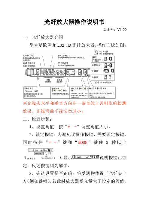
光纤放大器操作说明书
版本号:V1.00一:光纤放大器介绍
型号是欧姆龙E3X-HD光纤放大器,操作面板如图:
两光线头水平和垂直方向在一条直线上否则影响检测效果、光线弯曲半径切勿过小;
二、设置步骤:
1、设置阀值:按“+ -”调整阀值大小。
2、锁定按键:为避免误操作按键,需要锁定按键,同时按住“+ -”键和“MODE”键住3秒以上
(),显示说明按键已锁定,反之按键则为解锁。
3、确认设置是否正确:将受测物体置于光纤头上方(例如键帽),若此时放大器受光量大于设定的阀值,
OUT指示灯亮;移走受测物体后受光量小于阀值、OUT 指示灯灭,则说明设置正常。
三、初始化设置
附加
四、投光量的设定(受检测距离和检测环境的影响,当阀值设置最小也无法检测到时、需要增大投光量如下操作)
1、按“MODE”键3S以上进入“功能选择”;如右图
2、按“MODE”键、显示“检测模式”如右图
3、按“MODE”键选、显示“DPC功能”如右图
4、按“MODE”键进入、显示“定时功能”如右图
5、按“MODE”键进入、显示“光量调整等级”如
右图
单击“+/-”键调整投光量等级、MODE键返回。
- 1、下载文档前请自行甄别文档内容的完整性,平台不提供额外的编辑、内容补充、找答案等附加服务。
- 2、"仅部分预览"的文档,不可在线预览部分如存在完整性等问题,可反馈申请退款(可完整预览的文档不适用该条件!)。
- 3、如文档侵犯您的权益,请联系客服反馈,我们会尽快为您处理(人工客服工作时间:9:00-18:30)。
光纤放大器操作说明书
版本号:V1.00一:光纤放大器介绍
型号是欧姆龙E3X-HD光纤放大器,操作面板如图:
两光线头水平和垂直方向在一条直线上否则影响检测效果、光线弯曲半径切勿过小;
二、设置步骤:
1、设置阀值:按“+ -”调整阀值大小。
2、锁定按键:为避免误操作按键,需要锁定按键,同时按住“+ -”键和“MODE”键住3秒以上
(),显示说明按键已锁定,反之按键则为解锁。
3、确认设置是否正确:将受测物体置于光纤头上方(例如键帽),若此时放大器受光量大于设定的阀值,
OUT指示灯亮;移走受测物体后受光量小于阀值、OUT 指示灯灭,则说明设置正常。
三、初始化设置
附加
四、投光量的设定(受检测距离和检测环境的影响,当阀值设置最小也无法检测到时、需要增大投光量如下操作)
1、按“MODE”键3S以上进入“功能选择”;如右图
2、按“MODE”键、显示“检测模式”如右图
3、按“MODE”键选、显示“DPC功能”如右图
4、按“MODE”键进入、显示“定时功能”如右
图
5、按“MODE”键进入、显示“光量调整等级”
如右图
单击“+/-”键调整投光量等级、MODE键返回。