FS-V33光纤放大器说明书
无线信号放大器使用说明书

设备安装图示 一
双向无线信号放大器与无线路 由器的合影
设备安装步骤: Step1:先拆除无线路由器上
的天线。 Step2:拿出SMA连接线,连 接无线路由器与信号放大器 (TO Radio)。 Step3:在信号放大器的另一 端(TO Antenna)接上天线。
双向无线信 号放大器
设备安装图示 二
路由器上的天线。 Step2:拿出SMA连 接线,连接无线路由 器与信号放大器(TO Radio)。 Step3:在信号放大 器的另一端(TO Antenna)接上天线。
设备安装图示 四
放大器和无线路由器,高增 益天线连接图示
设备安装步骤: Step1:先拆除无线路由器
上的天线。 Step2:拿出SMA连接线, 无线路由器与信号放大器 (TO Radio)。 Step3:在信号放大器的另 一端(TO Antenna)接上高 增益天线。
号饱和造成失真。通讯两端的距离保持在50cm 以上则不会有此问题。 ■ 放大器应该安装在无线路由器上还是无线网卡上?
都可以安装,安装在无线路由器上可使所有与之建立连接的无线用户的信号得 到加强;安装在无线网卡上只能使该网卡的信号得到增强。 ■ 为何加了放大器仍然收索不到?
对方网络安装一个放大器可以使空旷覆盖距离增加 1~2 倍。若希望建立无线链 接的两个终端距离太远,此时建议用户在两个终端都安装放大器和并加装高增益定 向天线。 ■ 放大器的发射功率是不是越大越好?
的阻挡对信号的衰减也有30dB 以上,建议将天线尽量安装在障碍物少的 位置。 ■ 为什么有时候信号会变差?
2.4G ISM 频段是非常繁忙的频段,蓝牙、无线摄像机、Baby Monitor 和微波炉均使用此频段。建议把放大器天线安装在远离这些无线装置的 位置。也可切换路由器的工作频道试试,尽量远离干扰源。 放大器的红灯不亮? ■ 屏蔽线缆没有连接好,或者网卡-路由器之间没有通讯。
光纤放大器说明FS
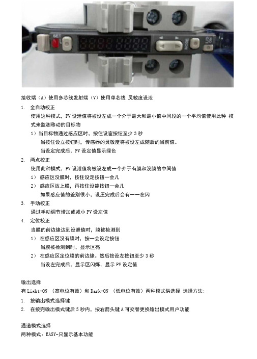
接收端(A)使用多芯线发射端(V)使用单芯线灵敏度设泄1.全自动校正使用这种模式,PV设泄值将被设左成一个介于最大和最小值中间段的一个平均值使用此种模式来监测移动的目标物1)当目标物通过感应区时,按住设宦按钮至少3秒当按住设立按钮时,传感器的灵敏度将被设左成随后的当前值。
当设定完成后,PV设定值显示绿色2.两点校正使用此种模式,PV设泄值将被设左成一个介于有膜和没膜的中间值1)感应区没膜时,按住设定按钮一会儿2)感应区放上膜,再按住设能按钮一会儿如果感应值的差别很小,设圧完成后会有一一在闪3.手动校正通过手动调节增加或减小PV设左值4.定位校正当膜的前边缘达到设泄值时,膜被检测到1)在感应区没有膜时,按一会设定按钮当膜被检测到时,显示区亮2)在感应区定位膜的前边缘。
然后按设左按钮至少3秒当设左完成后,显示区闪烁,显示PV设定值输出选择有Light-ON (髙电位有效)和Dark-ON (低电位有效)两种模式供选择选择方法:1.按输岀模式选择键2.在按完输出模式键后5秒内,按右箭头键A可交替更换输出模式用户功能通道模式选择两种模式:EASY-只显示基本功能FULL-所有功能均被显示按MODE键至少3秒,然后通过左右箭头选择模式显示选择(EASY模式)1.显示设建值和当前值例:PV区域50, CV区域122.显示增益和当前值例:PY区域24P (增益)。
如果按键30秒不操作,当前值将显示3.显示输出状态和电源模式状态例:PY区域L on, CY区域F inE如果设左立时器功能,输出状态和电源模式状态将交替显示显示选择(FULL模式)六种显示状态1.显示设左值和当前值2.显示增益和当前值3.显示LED指示条和当前值4.显示峰值和底值(最大和最小值)5.显示最大增益值和最小增益值&显示输出状态和电源模式菜单选择(EASY模式)1.按MODE键3秒进入通道模式选择(EASY或FULL)2.按MODE键进入电源模式选择,通过左右键选择1) F inE正常操作模式2)Turb (TURBO)如果传感器在正常模式(FINE)时感应距离不充足时,使用此种模式3)SuPr (SUPER TURBO)如果使用环境较差,灰尘或英他障碍物时使用此模式3.按MODE键进入计时器功能设定,通过左右键选择1)ToFF计时器关闭(正常模式)2)oFFd OFF延时计时器3 ) on~d ON延时计时器4)Shot One-shot 计时器4.按MODE进入Shot,通过按左右键调整讣时器值。
FS-V31-c光纤驱动器说明书
SEL
M
I/O( 輸入 / 輸出 ) 電路 ■ FS-V31/32/31M
■ FS-V31P/32P
光
保
電
護
感
電
測 器 主 電 路
保 護 電 路
過 電 流
路
棕色*1
監視器輸出(1至5V)*2
橙色*
最大100mA
黑色
負載
(控制輸出)
藍色*1
12至24VDC
光
輸入阻抗至少
電 感
10kΩ的裝置
測
器
5至40VDC
接收到的光強
若上限設定值小於或等於下限設定值,則模組將無
法響應。
OFF
即使滿足上述條件,在因為遲滯導致 HI 和 LO 值互相接
HI: 上限設定值
近時, 模組也無法響應。注意操作模組,檢驗數值是否
ON
有效。
LO: 下限設定值
OFF
■ 如何切換上限設定值 (HI) 和下限設定值 (LO) 按 按鈕時,“HI”或 “LO”和設定值會交替閃爍。 在畫面交替閃爍時,如果按 MODE( 模式 ) 按鈕,“HI”或 “LO”顯示會發生變化。 配置靈敏度設定值的方法與一般檢測模式相同。
外部輸入 [ 僅適用於 FS-V31C(P)/V32C(P) 的功能 ]
1 可以選擇外部輸入功能從外部輸入信號 (第 4 頁,第 4-C 項)。 2 可以短接各型號中的針 (2) 至少 2ms 來接收信號 (OFF( 關 :) 20ms)。如下圖所示。
FS-V31C/V32C
1針 *
+V
FS-V31 CP/V32CP
光纖插入記號
註 如果使用較薄的光纖模組,則需要使用隨其提供的轉接器。 如果沒有連接正確的轉接器,則薄型光纖模組將不能正確地檢測目標物。( 轉接器隨光纖模組提供。)
放大器操作说明

放大器操作说明一、放大器的设置1.打开Nexus 元件的电源并使Nexus 元件初始化。
2.如果Nexus 元件没有显示主菜单,则应按底下的“Home ”键,直到出现主菜单。
在主菜单上应有诸如“Amplifier Set -up (放大器设置)”,“Transducer Set -up (传感器设置)”等选项。
如照片1所示:3.滚动到“Amplifier Set -up (放大器设置)”并按底下的“↙”一次。
如照片2所示:照片 1照片 24.在“Amplifier Set -up (放大器设置)”菜单下,应通过在底下箭头键来滚动到“Hz ”,以确保“Hz ”显示加亮。
一旦“Hz ”显示加亮,则按 “Ch ↓”键。
随后应用“+”和“-”按键来设置Hz (频率)为A 。
一旦通道1设置为A ,则应按 “Ch ↓”键,并对通道2,3和4作同样的工作。
如果是2通道Nexus 元件,那么只需要编程两个通道。
当所有通道设置为A 时,按“Home ”键返回。
如照片3所示:然后,用“→”键移动到“Out (输出)”。
一旦“Out (输出)”被显示加亮,使用“Ch ↓”键和“+”与“-”键把每个通道都设置为316mV/Pa 。
当所有通道都设置为316mV/Pa 后,按“Home ”键返回。
最后回顾一下菜单,确保所有的通道都被分别设置在A 下,“Out ”输出为316 mV/Pa 。
当所有设置项都设置正确后,按“Home ”键返回。
如照片4所示:照片 3滚动到“Transducer Set -up (传感器设置)”下并按底下的“↙”一次。
如照片5所示:(此步可以省略,因为麦克风的灵敏度是自动识别的不用设置)编辑此菜单需要声学传感器的校准数值。
当得到校准数值后,滚动到“Sensitivity (灵敏度)”并按“Ch ↓”键。
如照片6所示:照片 4照片 5随后将处在显示加亮的十进制数值的通道#1。
用“+”与“-”键把此数值设置为对应于此通道/声学传感器的校准/灵敏度数值。
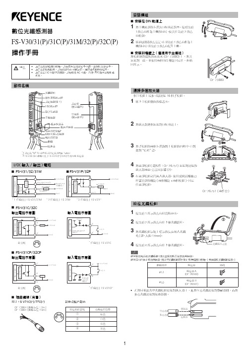
数字光纤传感器FS-V30 31(P) 31C(P) 31M 32(P) 32C(P)说明书
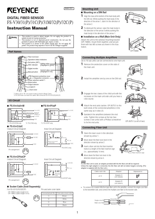
DIGITAL FIBER SENSORFS-V30/31(P)/31C(P)/31M/32(P)/32C(P)Instruction ManualI FS-V31/32/31MI FS-V31P/32P*1 FS-V31/31M only *2 FS-31M only *3 FS-V31P onlyI FS-V31C/32COutput Circuit DiagramInput Circuit DiagramI FS-V31CP/32CPOutput Circuit DiagramInput Circuit DiagramI Socket Cable (Sold Separately)For FS-V31C(P)/32C(P)Pin and wire color table2To dismount the sensor, raise the main body in the direction of the arrow 3 while pushing the both ends of the connected amplifiers in the same way as in step (2).5Sandwich the amplifiers between the end units. Tighten the screws at the top (twoscrews x two units) with a Phillips screwdriver to fix the end units.Move down the fiber lock lever in the direction shown by arrow 4.NoteIf a thin fiber unit is used, an adapter provided with the thin fiber unit will be required.Unless the right adapter is connected, the thin fiber unit will not detect targets correctly. (The adapter is supplied with the fiber unit.)•To connect the coaxial reflective type fiber unit to the amplifier, connect the single-core fiber to the transmitter side, and connect the multiple-core fiber to the receiver side.Pin assignmentPin assignmentOP-73864 (cable length:2 m)OP-73865 (cable length:10 m)with and without a workpiece.12after the calibration is complete. The set value is stored in memory even in that case.I Maximum Sensitivity SettingSet the sensitivity without a workpiece in the case of the reflective type, and with a workpiece in the case of the through-beam or retro-reflective type.Press the SET button for three seconds in the state as shown in the above figure.(Release the button when SET flashes.)When setting the sensitivity, set the value slightly higher than the received light intensity.I Full Auto CalibrationIn this mode, the PV will be set to the mean value of the maximum and minimum incident val-ues obtained within a certain period. Use this mode to detect moving workpieces.1Press the set button for a minimum of three seconds while the target workpiece is passing the sensing area of the fiber unit.•While the SET button is pressed, the sensitivity of the sensor will be set•After the setting is completed, the setting value is displayed on the digital monitor.I Positioning CalibrationFor example, if the target value is set to –10P , the setting value is determined 10% lower than the received light intensity when the SET button is pressed.1When selecting the sensitivity setting method (page 4, No. 2), select the % calibration, and set the target value of calibration.2Taking the desired light intensity as a reference (normally without a workpiece), press the SET button.*While the % calibration is in use, other calibrations (sensitivity setting) cannot be used.*With FS-V31C(P)/32C(P), by periodically performing external calibration from PLC or other devices, stable detection can be performed even with a small sensitivity difference.This function is effective when the light intensity difference is small when judging whether or not there is a workpiece.At Detection mode selection (page 4, No.4), select “Dynamic sensitivity correction mode” beforehand.*How to set the sensitivity is the same as in the normal mode.The DSC indicator illuminates when the DSC function is set.*When Light ON is selected, the upper limit of the correctable range is twice as much as the initial setting value.*The value is stored in memory even after the power is turned off.*The DSC indicator flashes when the light intensity during output OFF greatly fluctuates or the L/D ON selection is inappropriate. In such a case, check the setting again.•When using FS-V31C(P)/32C(P), external inputs can be used.•No inputs are accepted while setting each mode.When external calibration is selected, the operation is the same as with the SET button.I Special FunctionBy performing the following operation, both sensitivity setting and scaling can be performed using external input. Select external calibration (page 4, No. 4-C) and display scaling. The following is the example when using the % calibration.set by pressing the button for 2 seconds or longer.The same steps can be taken to deactivate key lock.For more information on the key lock levels and the PIN number key lock function, refer to page 6.Select “rSt “with the3Select “init” with theDefault settingPower mode:FINEDetection mode: NormalSetting value:50Output selection:L ONI Saving the settings1While pressing, press for 5 seconds or longer.2Select “SAvE” with the3Select “YES” with theI Loading the setting1While pressing , press for 5 seconds or longer.2Select “rSt” with the3Select “[vSt” with thebutton for 3 seconds or longer.Reference。
FS-V33光纤放大器说明书

型号:BT440C编制:文件编ZD-BT440C-1.2文件名:前规光电调整简易说明校对:客户:秋山服务网点批准:修改版01 页码: 1 KEYENCE(FS-V33)光纤放大器简易说明:一、零件名称:部件简易功能:1通道1输出指示:通道1检测值大于设定值时信号输出灯亮。
2通道2输出指示:通道2检测值大于设定值时信号输出灯亮。
3设定按钮:设定灵敏度和其他功能设定。
4设定值显示:功能显示和设定值显示。
(浅绿色)5检测值显示:显示检测值和功能显示。
(红色)6灵敏度调整按钮:修改设置值和选项切换。
7模式按钮:模式选择。
8输出选择钮:输出方式选择。
9通道选择开:通道1,2输出选择开关。
(应选择1上图为选择2)二、放大器上设置灵敏度:(一)两点校准该模式中,使用的设定值将是有无纸张时获得的两个检测值的平均值。
1在前规检测处没有纸时,按3“设定按钮”显示“set”,(见下图)。
型号:BT440-C编制:文件编ZD-BT440-C1.2文件名:前规光电调整简易说明校对:客户:秋山服务网点批准:修改版01 页码: 2 2在前规检测处有纸时,再按3“设定按钮”5"检测值"会增加,并显示设定值。
(二)最大灵敏度1在不放置纸张时,按3“设定按钮”至少3秒钟显示“set”,(见下图)。
2“set”不停闪烁时松开3“设定按钮”即可。
三、触摸屏上设置灵敏度:在光电光纤显示画面中按“前规设定”按钮,弹出前规检测设画面。
型号:BT440-C编制:文件编ZD-BT440-C1.2文件名:前规光电调整简易说明校对:客户:秋山服务网点批准:修改版01 页码: 3 (一)单个设定:一个前规设定。
1在前规检测处没有纸时,根据要设置的检测点,按相应“设置”按钮。
2在前规检测处有纸时,根据要设置的检测点,按相应“设置”按钮。
(二)整体设定:L侧和R侧同时前规设定。
1在前规检测处没有纸时,按“全体设置”按钮。
2在前规检测处有纸时,按“全体设置”按钮。
三光三相IO-Link电流监测保护电器说明书

100 000 K 2%
Supply voltage Type of voltage of the supply voltage Supply voltage 1 at DC rated value Relative negative tolerance of the supply voltage Relative positive tolerance of the supply voltage
DC 24 V 25 % 25 %
Measuring circuit Type of current for monitoring Adjustable pick-up value current ●1 ●2 Adjustable response delay time ● when starting ● with lower or upper limit violation Adjustable switching hysteresis for measured current value Accuracy of digital display
● at 24 V ● at 125 V ● at 250 V Contact rating of auxiliary contacts according to UL
Main circuit Operating power ● rated value
Outputs Ampacity of the semiconductor output in SIO mode Operating current at 17 V minimum
KEYENCE FS-V33(P) V34(P) V33C(P) V34C(P) 说明书
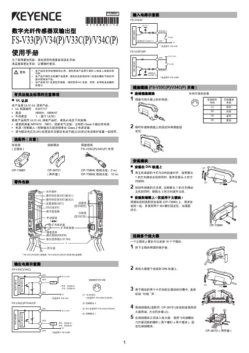
(3) 0V( 仅适用于 FS-V33C/V33CP)
(4) 控制输出 1
安装模块
安装在 DIN 轨道上
(3)
1 将主机底部的卡爪与DIN轨道对齐。按照箭头
1 的方向推动主机的同时,使其往箭头 2 的方
向倾斜。
(2)
2 拆卸传感器的方法是,在朝箭头 1 的方向推动
(1)
主机的同时,朝箭头 3 的方向提升主机。
1 选择灵敏度设置方法时 ( 第 5 页第 2 项 ),选择 % 校准,然后设置校准的目标值。 2 参考所需的光强 ( 通常不使用工件 ),按 SET( 设置 ) 按钮。
DSC 1
2
1
2
* 使用 % 校准时,不能使用其它校准 ( 灵敏度设置 )。
输出选择
可以选择 light-ON 模式或 dark-ON 模式。
(1)
听到“咔嗒”声。
4 将端部模块(选配件: OP-26751)安装到连接的放
大器两端,方法同步骤 (2)。
5 在端部模块之间夹入放大器。使用飞利浦螺丝
刀拧紧顶部的螺钉 ( 两个螺钉 x 两个模块 ),固 定住端部模块。
OP-26751 ( 两件套 )
1
连接光纤模块
1 按箭头 1 所示的方向开启防尘罩。 2 按箭头 2 所示的方向往下移光纤
• 请使用具备 NFPA70 (NEC:国家电气法规)注明的 Class 2 输出的电源。
• 电源 / 控制输入 / 控制输出只能连接单台 Class 2 电源设备。
• 请与额定电压为 24V 或更高并且额定电流不超过 2A 的过电流保护装置一起使用。
选配件 ( 另售 )
安装架 ( 主模块 )
- 1、下载文档前请自行甄别文档内容的完整性,平台不提供额外的编辑、内容补充、找答案等附加服务。
- 2、"仅部分预览"的文档,不可在线预览部分如存在完整性等问题,可反馈申请退款(可完整预览的文档不适用该条件!)。
- 3、如文档侵犯您的权益,请联系客服反馈,我们会尽快为您处理(人工客服工作时间:9:00-18:30)。
型号:BT440C编制:文件编号: ZD-BT440C-1.2 文件名:前规光电调整简易说明校对:
客户:秋山服务网点批准:修改版本: 01 页码: 1
KEYENCE(FS-V33)光纤放大器简易说明:
一、零件名称:
部件简易功能:
1通道1输出指示:通道1检测值大于设定值时信号输出灯亮。
2通道2输出指示:通道2检测值大于设定值时信号输出灯亮。
3设定按钮:设定灵敏度和其他功能设定。
4设定值显示:功能显示和设定值显示。
(浅绿色)
5检测值显示:显示检测值和功能显示。
(红色)
6灵敏度调整按钮:修改设置值和选项切换。
7模式按钮:模式选择。
8输出选择钮:输出方式选择。
9通道选择开:通道1,2输出选择开关。
(应选择1上图为选择2)
二、放大器上设置灵敏度:
(一)两点校准
该模式中,使用的设定值将是有无纸张时获得的两个检测值的平均值。
1在前规检测处没有纸时,按3“设定按钮”显示“set”,(见下图)。
型号:BT440-C编制:文件编
号:ZD-BT440-C1.2
文件名:前规光电调整简易说明校对:
客户:秋山服务网点批准:修改版
本:
01 页码: 2 2在前规检测处有纸时,再按3“设定按钮”5"检测值"会增加,并显示设定值。
(二)最大灵敏度
1在不放置纸张时,按3“设定按钮”至少3秒钟显示“set”,(见下图)。
2 “set”不停闪烁时松开3“设定按钮”即可。
三、触摸屏上设置灵敏度:
在光电光纤显示画面中按“前规设定”按钮,弹出前规检测设画面。
(一)单个设定:一个前规设定。
1在前规检测处没有纸时,根据要设置的检测点,按相应“设置”按钮。
2在前规检测处有纸时,根据要设置的检测点,按相应“设置”按钮。
(二)整体设定:L 侧和R 侧同时前规设定。
1在前规检测处没有纸时,按“全体设置”按钮。
2在前规检测处有纸时,按“全体设置”按钮。
四、当出现错误显示ErE(内部数据错误)需要执行初始化设置
(一般不操作)
1、按8“输出选择钮”同时按3“设定按钮”至少5秒钟。
(见下图)
号: 文件名:前规光电调整简易说明
校对:
客户:秋山服务网点
批准:
修改版本:
01 页码: 3
2、显示出“rSt ”后按7“模式按钮”将显示“no ”。
(见下图)
3、用6“灵敏度调整按钮”选择“init ”后按7“模式按钮” 结束初始化 。
(见下图)
号: 文件名:前规光电调整简易说明
校对:
客户:秋山服务网点
批准:
修改版本:
01 页码: 4。