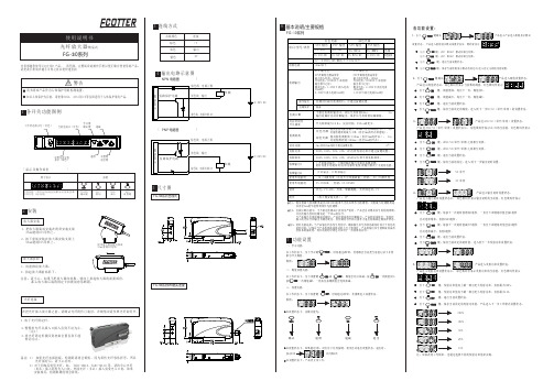
ECOTTER传感器光纤放大器FG-30说明书
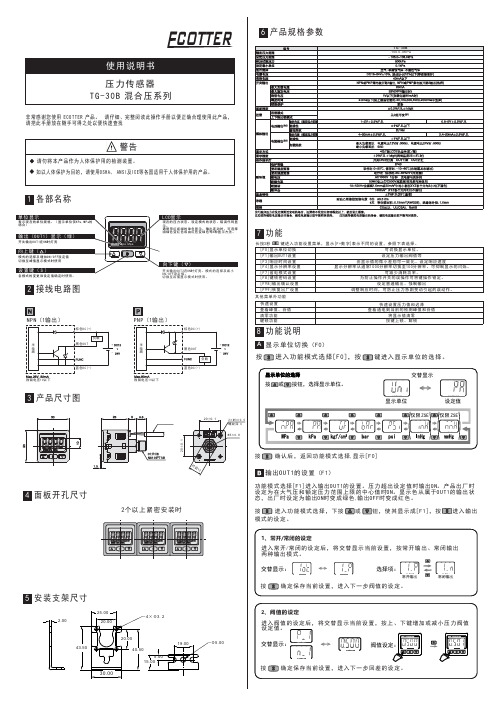
ECOTTER压力传感器TG-30B说明书
修改密码在显示解锁状态时,
同时按 键和
键进入密码修改设置。
L 显示错误
错误名称 过电流错误 残压错误 加压错误
错误显示
内容
处置方法
开 关 输 出 负 载 上 流 过8 0 m A以 上 的 电 流 。
切断电源,消除发生过电流场合的输出要因后, 再接通电源。
置 “0” 操 作 时 , 相 对 于 大 气 压 力 , 仍 有 ±3 . 5 % F . S .以 上 的 压 力。 但1秒 后 , 自 动 返 回 测 定 模 式 。 由 于 产 品 个 体 差 别 , 会 有 ±1 % F . S .置 “0” 设 定 范 围 的 不 同
按 进 入 功 能 模 式 选 择[ F 0 ], 按 键进入显示单位的选择。
显示单位的选择 按 或 按钮,选择显示单位。
交替显示
显示单位
设定值
2 0±0 . 1
2×M 3×0 . 5 螺纹深 4
M 5×0 . 8
仅限 ZSE 仅限 ZSE
20±0. 1
4 面板开孔尺寸
对 边1 2
2个 以 上 紧再进行置 “0” 操 作 。
加入超出设定压力范围上限的压力。 加入超出设定压力范围下限的压力。
让被加入的压力返回至设定压力范围内。
进入显示分辨率的设定后,将交替显示当前设置,按上、下键切换显示 分辨率。
交替显示:
分辨率切换:
1000 分辨率
按 确定保存当前设置,返回功能模式选择[F4]。
上锁状态 解锁状态
按 确定保存当前设置,返回功能选择模式[F1]。
响应时间设定(F3)
进入响应时间设置后,交替显示当前设置, 按上、下键选择响应时间。
交替显示
高速光纤光电探测器用户指南说明书

HIGH SPEED FIBER PHOTODETECTOR USER’S GUIDEThank you for purchasing your High Speed Fiber Photodetector. This user’s guide will help answer any questions you may have regarding the safe use and optimal operation of your Photodetector.TABLE OF CONTENTSI. High Speed Fiber Photodetector Overview ..................................................................................................... 1 II. Operation of your High Speed Fiber Photodetector ........................................................................................ 1 III. Troubleshooting ............................................................................................................................................... 2 IV. Drawings: High Speed Fiber Photodetectors ................................................................................................... 3 V. Specifications: High Speed Fiber Photodetectors ........................................................................................... 3 VI. Schematics: High Speed Fiber Photodetectors ................................................................................................ 4 VII. Glossary of Terms (5)I.High Speed Fiber Photodetector OverviewThe High Speed Fiber Photodetectors contain PIN photodiodes that utilize the photovoltaic effect to convert optical power into an electrical current. Figure 1 below identifies the main elements of your Fiber Photodetector.Figure 1: High Speed Fiber PhotodetectorWhen terminated into 50Ω into an oscilloscope, the pulsewidth of a laser can be measured. When terminated into a spectrum analyzer, the frequency response of a laser can be measured.II.Operation of your High Speed Fiber PhotodetectorA. Caution: Eye safety precautions must be followed when utilizing any equipment used in the vicinityof laser beams. Laser beams may reflect from the surface of the detector or the optical mount and caution must be exercised.B. Clean the end of the fiber ferrule and connect to the laser.C. Adjust the voltage of the oscilloscope to 50mV/division before connecting the detector.Power Switch3mm Furcation TubingBootSMA ConnectorD.Connect the detector to the oscilloscope using a coaxial cable designed for 10GHz operation.e the 50Ω termination input of the oscilloscope.F.After being certain that the damage threshold of the detector is not exceeded, turn on the laser.G.There is an internal 50Ωresistor at the output of the photodiode. This will cause the output current toyour test equipment to be half that of the photodiode output. For example, the output to yourequipment will be 450µA for a 1mW optical input at 0.9A/W. Some losses will also exist in the fibercable and connectors.III.TroubleshootingA.No signal is seen the first time the detector is used.1.Is the power switch on?2.Be certain that the signal is not high off scale on the oscilloscope.3.Is the wavelength of the laser within the spectral range of the detector?4.Has a 50Ω termination input been used?5.Make sure the fiber radius is greater than 1 inch. Inspect fiber for damage.6.Is there enough light (see sensitivity spec on the data sheet) incident on the detector to generate asignal?B. A signal has been previously obtained, but not currently.1.Try steps listed under A.2.Test the power supply:a.Units with internal batteries will typically operate for several years, but operation with CWor high rep rate lasers can drain the batteries much faster. If a load is present at the output,current will be drawn from the batteries, so disconnect the BNC when not in use.Remove top cover to replace the 3V lithium cells with Duracell Model DL2430, positive sidedown.b.Units with an external power supply should at least receive the voltage that is printed on theplug.C.Increasing the power incident on the detector does not result in a higher voltage signal on theoscilloscope:1.The detector is probably saturated. You should lower the power incident on the detector to alevel below the saturation point.IV.Drawings: High Speed Fiber PhotodetectorsA. 818-BB-35F, 818-BB-45F, 818-BB-51F Dimensions:V.Specifications: High Speed Fiber PhotodetectorsPart No. (Model) - Battery Bias 818-BB-35F 818-BB-45F 818-BB-51FRise Time/Fall Time (ps) <25/<25 <30/<30 28 Responsivity (A/W) >0.65 at 1300nm 0.38 at 830nm 0.95 at 2000nm Power Supply6V battery/5V external3V battery/5V external3V battery/5V externalSpectral Range (nm)830-1650 500-890 830-2150 Bandwidth>15GHz >12.5GHz>12.5GHzActive Area Diameter (µm) 32 60 40 Dark Current<3nA <0.5nA <1µA Noise Equivalent Power (pW/√Hz) <0.05 at 1300nm <0.03 at 830nm <0.6 at 2000nm Mounting (Tapped Hole) 8-32 or M4 8-32 or M4 8-32 or M4 Output Connector SMA SMA SMA Fiber Optic ConnectionFC/UPC, SMF 28eFC/UPC, SMF 28eFC/UPCVI. Schematics: High Speed Fiber PhotodetectorsVII. Glossary of TermsBandwidth: The range of frequencies from 0Hz (DC) to the frequency at which the amplitude decreases by 3dB. Bandwidth and rise time can be approximately related by the equation: Bandwidth ≈ 0.35/rise time for a Gaussian pulse input.Bias Voltage: The photodiode ’s junction capacitance can be modified by applying a reverse voltage. The bias voltage reduces the junction capacitance, which causes the photodiode to have a faster response.Dark Current: When a termination is present, a dark current (nA range) will flow if the photodiode is biased. Disconnecting the coaxial cable will prevent this current from flowing.Decoupling Capacitor: Maintains bias voltage when fast pulses cause the battery voltage to reduce (this would slow the response time of the photodiode ); the capacitor allows the battery to recover to its initial voltage. It also acts as a filter for external power supplies.Noise Equivalent Power (NEP): A function of responsivity and dark current and is the minimum optical power needed for an output signal to noise ratio of 1. Dark current is the current that flowsthrough a reverse biased photodiode even when light is not present, and is typically on the order of nA. Shot noise (Ishot) is a source of noise generated in part by dark current; in the case of reversed biased diodes it is the dominant contributor. NEP is calculated from shot noise and responsivity. For example, for a responsivity @ 830nm = 0.5 A/W:q = charge on an electronPhotodiode: Converts photons into a photocurrent.Resistor: Protects the photodiode from excessive current. This could occur if an external power supply was too high in voltage, or if its polarity were reversed; this happens when a customer uses their own power supply.Responsivity: In amps per watt (A/W), responsivity is the current output of the photodiode for a given input power, and is determined by the diode structure. Responsivity varies with wavelength and diode material.Rise time/Fall time: Rise Time is the time taken by a signal to change from a specified low value to a specified high value. Fall Time is the time taken for the amplitude of a pulse to decrease from a specified value to another specified value. A larger junction capacitance will slow the detector’s response time.SMA Connector: Used to connect the customer’s coaxial cable for high frequencies.Termination Resistor (50Ω): Reduces signal reflections and balances the 50Ω microstrip/coaxial cable lines. As a result, half the photodiode current is lost to the internal resistor.Hz 0.08pA/s 0.08pA )1020)(2(1.6x10=2_9-19===−A x As qI Noise Shot d Hz 0.16pW/0.5AW *08.0/R 830nm ===Hz pA I NEP shot。
光纤放大器的调节方法

光纤放大器的调节方法本页仅作为文档封面,使用时可以删除This document is for reference only-rar21year.March光纤放大器的调节方法无线光通信是以激光作为信息载体,是一种不需要任何有线信道作为传输媒介的通信方式。
与微波通信相比,无线光通信所使用的激光频率高,方向性强(保密性好),可用的频谱宽,无需申请频率使用许可;与光纤通信相比,无线光通信造价低,施工简便、迅速。
它结合了光纤通信和微波通信的优势,已成为一种新兴的宽带无线接人方式,受到了人们的广泛关注。
但是,恶劣的天气情况,会对无线光通信系统的传播信号产生衰耗作用。
空气中的散射粒子,会使光线在空间、时间和角度上产生不同程度的偏差。
大气中的粒子还可能吸收激光的能量,使信号的功率衰减,在无线光通信系统中光纤通信系统低损耗的传播路径已不复存在。
大气环境多变的客观性无法改变,要获得更好更快的传输效果,对在大气信道传输的光信号就提出了更高的要求,一般地,采用大功率的光信号可以得到更好的传输效果。
随着光纤放大器(EDFA)的迅速发展,稳定可靠的大功率光源将在各种应用中满足无线光通信的要求。
1 、EDFA的原理及结构掺铒光纤放大器(EDFA)具有增益高、噪声低、频带宽、输出功率高、连接损耗低和偏振不敏感等优点,直接对光信号进行放大,无需转换成电信号,能够保证光信号在最小失真情况下得到稳定的功率放大。
、 EDFA的原理在掺铒光纤中注入足够强的泵浦光,就可以将大部分处于基态的Er3+离子抽运到激发态,处于激发态的Er3+离子又迅速无辐射地转移到亚稳态。
由于 Er3+离子在亚稳态能级上寿命较长,因此很容易在亚稳态与基态之间形成粒子数反转。
当信号光子通过掺铒光纤时,与处于亚稳态的Er3+离子相互作用发生受激辐射效应,产生大量与自身完全相同的光子,这时通过掺铒光纤传输的信号光子迅速增多,产生信号放大作用。
Er3+离子处于亚稳态时,除了发生受激辐射和受激吸收以外,还要产生自发辐射(ASE),它造成EDFA的噪声。
光纤放大器说明FS
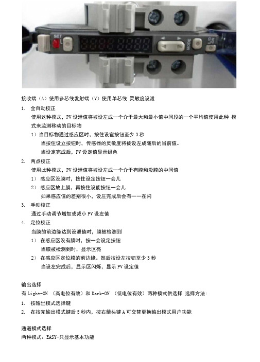
接收端(A)使用多芯线发射端(V)使用单芯线灵敏度设泄1.全自动校正使用这种模式,PV设泄值将被设左成一个介于最大和最小值中间段的一个平均值使用此种模式来监测移动的目标物1)当目标物通过感应区时,按住设宦按钮至少3秒当按住设立按钮时,传感器的灵敏度将被设左成随后的当前值。
当设定完成后,PV设定值显示绿色2.两点校正使用此种模式,PV设泄值将被设左成一个介于有膜和没膜的中间值1)感应区没膜时,按住设定按钮一会儿2)感应区放上膜,再按住设能按钮一会儿如果感应值的差别很小,设圧完成后会有一一在闪3.手动校正通过手动调节增加或减小PV设左值4.定位校正当膜的前边缘达到设泄值时,膜被检测到1)在感应区没有膜时,按一会设定按钮当膜被检测到时,显示区亮2)在感应区定位膜的前边缘。
然后按设左按钮至少3秒当设左完成后,显示区闪烁,显示PV设定值输出选择有Light-ON (髙电位有效)和Dark-ON (低电位有效)两种模式供选择选择方法:1.按输岀模式选择键2.在按完输出模式键后5秒内,按右箭头键A可交替更换输出模式用户功能通道模式选择两种模式:EASY-只显示基本功能FULL-所有功能均被显示按MODE键至少3秒,然后通过左右箭头选择模式显示选择(EASY模式)1.显示设建值和当前值例:PV区域50, CV区域122.显示增益和当前值例:PY区域24P (增益)。
如果按键30秒不操作,当前值将显示3.显示输出状态和电源模式状态例:PY区域L on, CY区域F inE如果设左立时器功能,输出状态和电源模式状态将交替显示显示选择(FULL模式)六种显示状态1.显示设左值和当前值2.显示增益和当前值3.显示LED指示条和当前值4.显示峰值和底值(最大和最小值)5.显示最大增益值和最小增益值&显示输出状态和电源模式菜单选择(EASY模式)1.按MODE键3秒进入通道模式选择(EASY或FULL)2.按MODE键进入电源模式选择,通过左右键选择1) F inE正常操作模式2)Turb (TURBO)如果传感器在正常模式(FINE)时感应距离不充足时,使用此种模式3)SuPr (SUPER TURBO)如果使用环境较差,灰尘或英他障碍物时使用此模式3.按MODE键进入计时器功能设定,通过左右键选择1)ToFF计时器关闭(正常模式)2)oFFd OFF延时计时器3 ) on~d ON延时计时器4)Shot One-shot 计时器4.按MODE进入Shot,通过按左右键调整讣时器值。
使用说明书-Adafruit SGP30 TVOC eCO2 气体传感器
Adafruit SGP30 TVOC/eCO2 Gas SensorCreated by lady adahttps:///adafruit-sgp30-gas-tvoc-eco2-mox-sensorLast updated on 2022-12-01 03:09:00 PM EST36713132020Table of ContentsOverview Pinouts• Data Pins • Power Pins:Arduino Test• Wiring• Install Adafruit_SGP30 library • Load Demo• Baseline Set & GetArduino Library Docs Python & CircuitPython Test• CircuitPython MicroController Wiring • Python Computer Wiring• CircuitPython Installation of SGP30 Library • Python Installation of SGP30 Library • CircuitPython & Python Usage • Baseline Set & GetPython Library Docs Download• Files:• Schematic STEMMA QT Version• Fabrication Print STEMMA QT Version• Schematic & Fabrication Print Original VersionOverviewBreathe easy with the SGP30 Multi-Pixel Gas Sensor, a fully integrated MOX gas sensor. This is a very fine air quality sensor from the sensor experts at Sensirion, with I2C interfacing and fully calibrated output signals with a typical accuracy of 15% within measured values. The SGP combines multiple metal-oxide sensing elements on one chip to provide more detailed air quality signals.This is a gas sensor that can detect a wide range of Volatile Organic Compounds (VOCs) and H2 and is intended for indoor air quality monitoring. When connected to your microcontroller (running our library code) it will return a Total Volatile OrganicCompound (TVOC) reading and an equivalent carbon dioxide reading (eCO2) overI2C.The SGP30 has a 'standard' hot-plate MOX sensor, as well as a small microcontroller that controls power to the plate, reads the analog voltage, tracks the baseline calibration, calcluates TVOC and eCO2 values, and provides an I2C interface to read from. Unlike the CCS811, this sensor does not require I2C clock stretching. Array This part will measure eCO2 (equivalent calculated carbon-dioxide) concentrationwithin a range of 400 to 60,000 parts per million (ppm), and TVOC (Total VolatileOrganic Compound) concentration within a range of 0 to 60,000 parts perbillion (ppb).Please note, this sensor, like all VOC/gas sensors, has variability and to get precise measurements you will want to calibrate it against known sources! That said, for general environmental sensors, it will give you a good idea of trends and comparison. The SGP30 does have built in calibration capabilities, note that eCO2 is calculated based on H2 concentration, it is not a 'true' CO2 sensor for laboratory use.Another nice element to this sensor is the ability to set humidity compensation for better accuracy. An external humidity sensor is required and then the RH% is written over I2C to the sensor, so it can better calculate the TVOC/eCO2 values.Nice sensor right? So we made it easy for you to get right into your next project. The surface-mount sensor is soldered onto a custom made PCB in the STEMMA QT form factor (), making them easy to interface with. The STEMMA QT connectors () on either side are compatible with the SparkFun Qwiic () I2C connectors. This allows you to make solderless connections between your development board and the SGP30 or to chain it with a wide range of other sensors and accessories using a compatible cable ( ).We’ve of course broken out all the pins to standard headers and added a 1.8V voltage regulator and level shifting so allow you to use it with either 3.3V or 5V systems suchas the Raspberry Pi, or Metro M4 or Arduino Uno.PinoutsPower Pins:Vin - this is the power pin. Since the sensor chip uses 3 VDC for logic, we have included a voltage regulator on board that will take 3-5VDC and safely convert it down. To power the board, give it the same power as the logic level of your microcontroller - e.g. for a 5V micro like Arduino, use 5V1V8 - this is the 1.8V output from the voltage regulator, you can grab up to 50mA from this if you likeGND - common ground for power and logicData PinsSCL - I2C clock pin, connect to your microcontrollers I2C clock line. Can use 3V or 5V logic, and has a 10K pullup to VinSDA - I2C data pin, connect to your microcontrollers I2C data line. Can use 3V or 5V logic, and has a 10K pullup to VinSTEMMA QT () - These connectors allow you to connectors to dev boards with S TEMMA QT connectors or to other things with various associated accessories ()Arduino TestYou can easily wire this breakout to any microcontroller; we'll be using an Arduino.• • • • • •Start by soldering the headers to the SGP30 breakout board. Check out the Adafruit guide to excellent soldering () if you're new to soldering. Then continue on below to learn how to wire it to a Metro.The sensor uses I2C address 0x58 and cannot be changed.WiringConnect the SGP30 breakout to your board using an I2C connection. Here's an example with an Arduino-compatible Metro:Board 5V to Sensor Vin (red wire onSTEMMA QT version). (Metro is a 5V logicchip)Board ground / GND to sensor ground /GND (black wire on STEMMA QT version).Board SCL to sensor SCL (yellow wire onSTEMMA QT version).Board SDA to sensor SDA (blue wire onSTEMMA QT version).Metro Original Fritzing FileInstall Adafruit_SGP30 libraryTo begin reading sensor data, you will need to install the Adafruit_SGP30 library (code on our github repository) (). It is available from the Arduino library manager so we recommend using that.From the IDE open up the library manager...And type in adafruit sgp30 to locate the library. Click InstallLoad DemoOpen up File->Examples->Adafruit_SGP30->sgp30test and upload to your microcontroller wired up to the sensorThen open up the serial console at 115200 baud, you'll see the serial number printed out - this is a unique 48-bit number burned into each chip. Since you may want to doper-chip calibration, this can help keep your calibration detail separateThe first 10-20 readings will always be TVOC 0 ppb eCO2 400 ppm. That's because the sensor is warming up, so it will have 'null' readings.After a few seconds, you will see the TVOC and eCO2 readings fluctuate: ArrayEvery minute or so you'll also get a Baseline value printed out. More about that later!You can take a bit of alcohol on a swap and swipe it nearby to get the readings tospikeThat's it! The sensor pretty much only does that - all the calculations for the TVOC and eCO2 are done within the sensor itself, no other data is exposed beyond the'baseline' valuesBaseline Set & GetAll VOC/gas sensors use the same underlying technology: a tin oxide element that, when exposed to organic compounds, changes resistance. The 'problem' with these sensors is that the baseline changes, often with humidity, temperature, and other non-gas-related-events. To keep the values coming out reasonable, you'll need to calibrate the sensor.If no stored baseline is available after initializing the baseline algorithm,the sensor has to run for 12 hours until the baseline can be stored. This willensure an optimal behavior for the next time it starts up. Reading out thebaseline prior should be avoided unless a valid baseline is restored first.Once the baseline is properly initialized or restored, the current baselinevalue should be stored approximately once per hour. While the sensor isoff, baseline values are valid for a maximum of seven days.Restarting the sensor without reading back a previously stored baselinewill result in the sensor trying to determine a new baseline. Theadjustement algorithm will be accelerated for 12hrs which is the Maximumtime required to find a new baseline.The sensor adjusts to the best value it has been exposed to. So keeping itindoors the sensor thinks this is the best value and sets it to ~0ppb tVOCand 400ppm CO2eq. As soon as you expose the sensor to outside air itcan adjust to the global H2 Background Signal. For normal Operationexposing the sensor to outside air for 10min cumulative time should besufficient.If you're experienced with sensors that don't have a baseline, you eitherwon't be able to measure absolute values or you'll have to implement yourown baseline algorithm.The sensor to sensor variation of SGP30 in terms of sensitivity is very goodas each of them is calibrated. But the baseline has to be determined foreach sensor individually during the first Operation.To make that easy, SGP lets you query the 'baseline calibration readings' from the sensor with code like this:uint16_t TVOC_base, eCO2_base;sgp.getIAQBaseline(&eCO2_base, &TVOC_base);This will grab the two 16-bit sensor calibration words and place them in the variables so-named.You should store these in EEPROM, FLASH or hard-coded. Then, next time you start up the sensor, you can pre-fill the calibration words withsgp.setIAQBaseline(eCO2_baseline, TVOC_baseline); Arduino Library DocsArduino Library Docs ()Python & CircuitPython TestIt's easy to use the SGP30 sensor with Python or CircuitPython and the Adafruit CircuitPython SGP30 () module. This module allows you to easily write Python code that reads the TVOC, eCO2, and more from the sensor.You can use this sensor with any CircuitPython microcontroller board or with a computer that has GPIO and Python thanks to Adafruit_Blinka, our CircuitPython-for-Python compatibility library ().CircuitPython MicroController Wiring Connect the SGP30 breakout to your board using an I2C connection, exactly as shown on the previous page for Arduino. Here's an example with a Feather M0:Board 3.3V to sensor Vin (red wire onSTEMMA QT version) (Feather is 3.3Vlogic)Board ground / GND to sensor ground /GND (black wire on STEMMA QT version).Board SCL to sensor SCL (yellow wire onSTEMMA QT version).Board SDA to sensor SDA (blue wire onSTEMMA QT version).Feather Original Fritzing filePython Computer WiringSince there's dozens of Linux computers/boards you can use we will show wiring for Raspberry Pi. For other platforms, please visit the guide for CircuitPython on Linux to see whether your platform is supported ().Here's the Raspberry Pi wired with I2C:Pi 3V3 to sensor VIN (red wire on STEMMAQT version)Pi GND to sensor GND (black wire onSTEMMA QT version)Pi SCL to sensor SCL (yellow wire onSTEMMA QT version)Pi SDA to sensor SDA (blue wire onSTEMMA QT version)CircuitPython Installation of SGP30 Library To use the SGP30 you'll need to install the Adafruit CircuitPython SGP30 () library on your CircuitPython board.First make sure you are running the latest version of Adafruit CircuitPython () for your board.Next you'll need to install the necessary libraries to use the hardware--carefully follow the steps to find and install these libraries from Adafruit's CircuitPython library bundle(). Our introduction guide has a great page on how to install the library bundle () for both express and non-express boards.Remember for non-express boards like the, you'll need to manually install the necessary libraries from the bundle:adafruit_sgp30.mpyadafruit_bus_deviceYou can also download the adafruit_sgp.mpy from its releases page on Github ().Before continuing make sure your board's lib folder or root filesystem has the adafruit _sgp30.mpy, and adafruit_bus_device files and folders copied over.Next connect to the board's serial REPL ()so you are at the CircuitPython >>> prompt.Python Installation of SGP30 LibraryYou'll need to install the Adafruit_Blinka library that provides the CircuitPythonsupport in Python. This may also require enabling I2C on your platform and verifying you are running Python 3. Since each platform is a little different, and Linux changes often, please visit the CircuitPython on Linux guide to get your computer ready ()!Once that's done, from your command line run the following command:sudo pip3 install adafruit-circuitpython-sgp30If your default Python is version 3 you may need to run 'pip' instead. Just make sure you aren't trying to use CircuitPython on Python 2.x, it isn't supported!• • •CircuitPython & Python UsageTo demonstrate the usage of the sensor we'll initialize it and read the eCO2 and TVOC data and print it to the REPLSave this example sketch as main.py on your CircuitPython board:# SPDX-FileCopyrightText: 2021 ladyada for Adafruit Industries# SPDX-License-Identifier: MIT""" Example for using the SGP30 with CircuitPython and the Adafruit library""" import timeimport boardimport busioimport adafruit_sgp30i2c = busio.I2C(board.SCL, board.SDA, frequency=100000)# Create library object on our I2C portsgp30 = adafruit_sgp30.Adafruit_SGP30(i2c)print("SGP30 serial #", [hex(i) for i in sgp30.serial])sgp30.set_iaq_baseline(0x8973, 0x8AAE)sgp30.set_iaq_relative_humidity(celsius=22.1, relative_humidity=44)elapsed_sec = 0while True:print("eCO2 = %d ppm \t TVOC = %d ppb" % (sgp30.eCO2, OC))time.sleep(1)elapsed_sec += 1if elapsed_sec > 10:elapsed_sec = 0print("**** Baseline values: eCO2 = 0x%x, TVOC = 0x%x"% (sgp30.baseline_eCO2, sgp30.baseline_TVOC))In the REPL you'll see the serial number printed out: [0x0, 0x64, 0xb878] in this case. This is a unique 48-bit number burned into each chip. Since you may want to do per-chip calibration, this can help keep your calibration detail separateThe first 10-20 readings will always be eCO2 400 ppm TVOC 0 ppb . That's because the sensor is warming up, so it will have 'null' readings.After a few seconds, you will see the TVOC and eCO2 readings fluctuateEvery minute or so you'll also get a Baseline value printed out. More about that later!You can take a bit of alcohol on a swap and swipe it nearby to get the readings to spikeThat's it! The sensor pretty much only does that - all the calculations for the TVOC andeCO2 are done within the sensor itself, no other data is exposed beyond the'baseline' valuesBaseline Set & GetAll VOC/gas sensors use the same underlying technology: a tin oxide element that, when exposed to organic compounds, changes resistance. The 'problem' with these sensors is that the baseline changes, often with humidity, temperature, and other non-gas-related-events. To keep the values coming out reasonable, you'll need to calibrate the sensor.If no stored baseline is available after initializing the baseline algorithm,the sensor has to run for 12 hours until the baseline can be stored. This willensure an optimal behavior for preceding startups. Reading out thebaseline prior should be avoided unless a valid baseline is restored first.Once the baseline is properly initialized or restored, the current baselinevalue should be stored approximately once per hour. While the sensor isoff, baseline values are valid for a maximum of seven days.Restarting the sensor without reading back a previously stored baselinewill result in the sensor trying to determine a new baseline. Theadjustement algorithm will be accelerated for 12hrs which is the Maximumtime required to find a new baseline.The sensor adjusts to the best value it has been exposed to. So keeping itindoors the sensor thinks this is the best value and sets it to ~0ppb tVOCand 400ppm CO2eq. As soon as you expose the sensor to outside air itcan adjust to the global H2 Background Signal. For normal Operationexposing the sensor to outside air for 10min cumulative time should besufficient.If you're experienced with sensors that don't have a baseline, you eitherwon't be able to measure absolute values or you'll have to implement yourown baseline algorithm.The sensor to sensor variation of SGP30 in terms of sensitivity is very goodas each of them is calibrated. But the baseline has to be determined foreach sensor individually during the first Operation.To make that easy, SGP lets you query the 'baseline calibration readings' from the sensor with code like this:co2eq_base, tvoc_base = sgp30.baseline_co2eq, sgp30.baseline_tvocThis will grab the two 16-bit sensor calibration words and place them in the variables so-named.You should store these in EEPROM, FLASH or hard-coded. Then, next time you start up the sensor, you can pre-fill the calibration wordswith sgp30.set_iaq_baseline(co2eq_base, tvoc_base)Python Library Docs Python Library Docs () DownloadFiles:SGP30 Datasheet () Fritzing object in Adafruit Fritzing library () EagleCAD files on GitHub ()Schematic STEMMA QT Version• • •Fabrication Print STEMMA QT VersionSchematic & Fabrication Print OriginalVersion。
ECOTTER传感器光纤放大器FG-30说明书
200%
100%
50%
25%
12% 注:如需改变工作频率,也通过选择不同的发射功率值来实现。
-
+
-
+
-
+
-
+
6、
产品进入工作模式设置状态。
产品进入工作模式设置状态后,绿色数码管显示工作模式的当前值,红色数 INC 键,在对射和反射模式间相互切换。 压下 DEC 键,在对射和反射模式间相互切换。 压下 SET 键,退出当前设置状态。 压下 TEACH 键,保存当前工作模式的设定值,产品进入下一步工作模式。
* 注3
2 0 0 % , 1 0 0 %,5 0 %,2 5 %,1 2 %五 种 发 射 功 率 可 通 过 按 键 设 置 。
发射频率 特 殊 输 出1
特 殊 输 出2 使用环境温度 使用环境湿度 材质
2 0 0 % , 1 0 0 %,5 0 %,2 5 %,1 2 %对 应 五 种 不 同 发 射 频 率 。 上升沿脉冲输出、下降沿脉冲输出可通过按键设置, 延 时 设 置 中 的 延 时 时 间,即 为 脉 冲 宽 度,此 输 出 模 式 下 无 延 时 功 能 。
1.放下光纤固定杆。
2.慢慢将光纤从插入口插入直到不动为止。 ( 注1)
3.将光纤固定杆拨回到初始位置直到不能 转动为止。
蓝色线 电源负极 0V
< PNP 电路图
>
棕色线 电源正极
短路保护电路
黑色线 输出 蓝色线 电源负极 0V
负载
主控电路
5 尺寸图
FG-30系列出线式
FG-30系列M8插头连接
备注: 1) 如果光纤未插到底,检测距离将会缩短。因为柔性光纤容易折弯,所以 光纤插好后,请小心应对。
ECOTTER压力传感器TG-30AF说明书
显 示 分 辨 率[ F 4 ]
进入显示分辨率的设定后,将交替显示当前设置,按上、下键切换显示 分辨率。
交替显示:
分辨率切换:
1000 分辨率
按 确定保存当前设置,返回功能模式选择[F4]。
100 分辨率
省电模式设置
进入省电模式的设定后,将交替显示当前设置,按上、下键打开或关闭。 省 电 模 式 打 开 , 工 作 状 态 下 ,3 0秒 无 操 作 , 则 进 入 省 电 状 态 。
修改密码在显示解锁状态时,
同时按 键和
键进入密码修改设置。
L 显示错误
错误名称 过电流错误 残压错误 加压错误
错误显示
内容
处置方法
开 关 输 出 负 载 上 流 过8 0 m A以 上 的 电 流 。
切断电源,消除发生过电流场合的输出要因后, 再接通电源。
置 “0” 操 作 时 , 相 对 于 大 气 压 力 , 仍 有 ±3 . 5 % F . S .以 上 的 压 力。 但1秒 后 , 自 动 返 回 测 定 模 式 。 由 于 产 品 个 体 差 别 , 会 有 ±1 % F . S .置 “0” 设 定 范 围 的 不 同
主电路 主电路
N P N(1输 出 )
棕 色D C ( + )
负载
黑 色O U T
+
-
残 留 电 压1 V以 下
蓝色DC ( - )
3 产品尺寸图
P N P(1输 出 )
棕 色D C ( + )
残 留 电 压1 V以 下
+ 黑 色O U T
负载
蓝 色D C ( - )
7 功能
长按3秒 键 进 入功 能 设置 菜单, 显示[ F+数字]表示 不同的 设置 , 参照 下表选 择。
光纤放大器的调节方法.docx
光纤放大器的调节方法无线光通信是以激光作为信息载体,是一种不需要任何有线信道作为传输媒介的通信方式。
与微波通信相比,无线光通信所使用的激光频率高,方向性强( 保密性好 ) ,可用的频谱宽,无需申请频率使用许可;与光纤通信相比,无线光通信造价低,施工简便、迅速。
它结合了光纤通信和微波通信的优势,已成为一种新兴的宽带无线接人方式,受到了人们的广泛关注。
但是,恶劣的天气情况,会对无线光通信系统的传播信号产生衰耗作用。
空气中的散射粒子,会使光线在空间、时间和角度上产生不同程度的偏差。
大气中的粒子还可能吸收激光的能量,使信号的功率衰减,在无线光通信系统中光纤通信系统低损耗的传播路径已不复存在。
大气环境多变的客观性无法改变,要获得更好更快的传输效果,对在大气信道传输的光信号就提出了更高的要求,一般地,采用大功率的光信号可以得到更好的传输效果。
随着光纤放大器(EDFA)的迅速发展,稳定可靠的大功率光源将在各种应用中满足无线光通信的要求。
1、 EDFA的原理及结构掺铒光纤放大器(EDFA)具有增益高、噪声低、频带宽、输出功率高、连接损耗低和偏振不敏感等优点,直接对光信号进行放大,无需转换成电信号,能够保证光信号在最小失真情况下得到稳定的功率放大。
、 EDFA 的原理在掺铒光纤中注入足够强的泵浦光,就可以将大部分处于基态的Er3+ 离子抽运到激发态,处于激发态的 Er3+ 离子又迅速无辐射地转移到亚稳态。
由于Er3+离子在亚稳态能级上寿命较长,因此很容易在亚稳态与基态之间形成粒子数反转。
当信号光子通过掺铒光纤时,与处于亚稳态的Er3+ 离子相互作用发生受激辐射效应,产生大量与自身完全相同的光子,这时通过掺铒光纤传输的信号光子迅速增多,产生信号放大作用。
Er3+离子处于亚稳态时,除了发生受激辐射和受激吸收以外,还要产生自发辐射(ASE) ,它造成EDFA 的噪声。
、 EDFA 的结构典型的EDFA结构主要由掺铒光纤(EDF)、泵浦光源、耦合器、隔离器等组成。
劳易测光纤放大器说明书
劳易测光纤放大器说明书一、产品介绍劳易测光纤放大器是一种专为提高光纤通信系统灵敏度和动态范围而设计的器件。
该产品基于先进的erbium-doped fiber amplifier (铒纤放大器)技术,可对1550nm波长的光信号进行放大,从而实现长距离高质量的光纤传输。
二、特点1. 高增益,低噪声:采用优化的erbium-doped fiber amplifier (铒纤放大器)模块,具有高灵敏度和低噪声的特点。
2. 宽动态范围:可处理低功率信号,同时放大高功率信号,为光纤通信系统提供稳定的性能。
3. 多模/单模光纤兼容:适用于多模和单模光纤,提供灵活的光纤配置选项。
4. 温度稳定性:具有优化的温度控制机制,可在宽温范围内保持稳定的性能。
5. 易于集成:设计小巧,方便集成到各种光纤通信系统中。
三、技术规格1. 工作波长:1550nm2. 增益范围:10-30dB3. 噪声系数:低于5dB4. 动态范围:大于30dB5. 偏振相关损耗:小于0.5dB6. 工作温度:-20℃至+60℃四、安装说明1. 请确保设备已正确接地,并按照设备要求提供稳定的电源。
2. 将输入和输出光纤正确连接至设备接口。
确保连接头清洁,无灰尘或污染。
3. 根据系统要求,设置设备参数,例如增益、噪声系数等。
五、使用说明1. 在使用前,请仔细阅读本说明书,并确保理解所有操作步骤和注意事项。
2. 请勿超过设备的增益、噪声系数等技术参数极限。
3. 请勿在设备故障时继续使用,如出现任何异常情况,应立即切断电源。
六、常见问题及解答问题1:光纤连接器接触不良会导致什么现象?解答:光纤连接器接触不良可能会导致信号丢失、噪音增加等问题。
请检查连接头的安装情况,确保连接紧密。
问题2:设备温度过高是什么原因?解答:设备温度过高可能是由于环境温度过高、设备内部散热不良等原因。
请在通风良好的环境下使用设备,并确保设备散热器工作正常。
问题3:设备增益过低会对系统产生什么影响?解答:设备增益过低可能会导致系统动态范围减小,传输信号质量下降。
GigMaster 30 管理指南 管道电子吉他放大器说明书
Operator's ManualTube Guitar AmplifierPlease, first read this manual carefully!GigMaster 30Front Panel FeaturesGigMaster 30. This compact tube-driven amp delivers to-die-for tone in a phenomenally portable package! Either version, Combo or Head, is your perfect sidekick for playing gigs, recording in studios, and practicing at home. It comes loaded with a bevy of convenient sound-sculpting features designed to make your musical life easier and more rewarding, including a built-in spring reverb, Gain Boost, and Master Volume Boost. This M.V.B. lets you access two different master volume levels on the fly via footswitch, for example, one for rhythm and the other for leads.Four EL84 pentode power tubes serve up the amp's sweet fundamental sound, while the preamp's ECC83 double triode dishes out lashings of overdrive and distortion. What's more, the GigMaster 30 sports two channels, Clean and Lead, to give you an even wider variety of tonal flavors. And its Mid Boost switch accentuates those middle frequencies that mean so much to the sound of an electric guitar. Six sound-shaping may be controlled remotely via footswitch, which gives you lots of tonal flexibility paired with utmost handling ease! This ingenious little amp is sure to delight with its warm, bluesy tone and assertive mids. But don't take our word for it - plug in, play, and enjoy!You'll find guidelines on care and maintenance of tube amps handling in certain places of this manual. Please read and heed these before operating your amp. You'll also come across boxes shaded grey throughout the manual. These are located between the descriptions of the amp's functions and contain handy tips on the preceding function. All critical information pertaining to the operation of this amp is preceded by "NOTE" or "CAUTION." Please pay particular attention to these safety tips. The ENGL team wishes you all the best —may you and your amp enjoy a "harmonically rich" future together!1 Input: ¼" unbalanced input jack. Plug your guitar in here using a shielded cord.2 Input Gain: This knob controls the preamp's input sensitivity. Use to dial in the desired amount of gain for the Clean and Lead channels. It and the Master (12) knob determine the Clean channel's amount of preamp distortion in Lead mode.Note: The amp's noise floor will increase appreciably if you crank both the Lead Drive and Input Gain knobs!CAUTION: Extremely high gain and volume levels in Lead mode can produce powerful feedback. Avoid feedback squeals; they can lead to hearing loss and damage speakers! At higher volumes, 5 Middle: Mid-range voicing control of the preamps ´s passive EQ.7 Reverb: Reverb intensity knob. Twist it to adjust the amount of reverb for Clean and Lead. Turn the Reverb control knob clockwise to increase the effect's intensity. The signal remains completely dry when the knob is set to the 7 o'clock position or if Reverb is deactivated via a footswitch. You can switch the reverb unit on and off using a footswitch connected to jack 18. The reverb unit is always on if you do not plug a footswitch into jack 18.8 Lead Volume: Volume control for the Lead channel (pre-FX loop, influences the Send level).The red LED above the channel switching selector (11) indicates Lead operating mode.Use this knob to dial in the desired balance of levels between the Lead and Clean channels.9 Mid Boost: This voicing feature operates globally, affecting both channels by boosting specificmidrange frequencies when activated. The LED above the button lights up to indicate Mid Boostis activated. It may also be switched using a footswitch connected to jack 19.above the button lights up to indicate Gain Boost is engaged. You can also control Gain BoostThis function can also be activated via the respective footswitch connected to jack 20.Once a footpedal is connected, the channel selector pushbutton is deactivated.12 Master: This master volume knob controls the power amp's output (it is located post FX Loop).M.V.B. (Master Volume Boost): This feature increases the master volume level, giving you instant access to two different volume levels for different musical situations, for instance, one for rhythm parts and the other for lead lines.You can control this feature via a footswitch connected to port 19.13 Power Tube Fuse: This red LED lights up to indicate one of the internal power tube fuses hasblown. You can continue playing, but the amp's performance will be diminished. Normally theloss of a power tube results in an unbalanced signal.Be sure to have a specialist look over the power amp as soon as possible; the fuse probably blew because of a defective power tube. Once a fuse has blown, it must be replaced by a new fuse.14 Stand By: Power amp standby switch: Use this switch to silence (0 position) the amp when youtake a break. The amp's tubes stay warm, which means that it is ready to roll immediatelywhen you switch it back to full power. The standby switch is also well-suited for muting the ampPlease note: ensure that the Stand By switch (14) is set to Stand By (0 position) before you switch the amp on. Let the tubes heat up for about 30 seconds before you activate the power amp. This procedure spares the tubes.CAUTION: After an extended period of operation and higher ambient temperatures the amps'schassis can become very hot, therefore avoid touching the rear panel surface !16 Mains Connector (AC Power Inlet; IEC - C14 connector)Plug the mains cord in here. For European models, use a standard non-heating equipment connector cable.CAUTION: Make sure you use an intact mains line cord with a grounded plug! Before you power the amp up, ensure the voltage value printed alongside the mains socket is the same as the current of the local power supply or wall outlet.Please also heed the guidelines set forth in the separately included pamphlet, Instructions for the Prevention of Fire, Electrical Shock and Injury.17 Mains Fuse Box: The rear chamber contains the mains fuse and in the front chamber, a spare fuse. CAUTION: ALWAYS make sure replacement fuses are of the same type and have the same ratings as the original fuse! Please refer to the fuse ratings table.18 Footswitch FX Off/On; Reverb: Use this ¼" Stereo jack to connect a conventional footswitch with two switching functions, for example, the ENGL Z-4 (2 x off/on - Single Pole Single Throw or SPST for short). This type of footswitch lets you switch the FX Loop and Reverb off and on. One of the two switches activates the FX Loop; the other engages the internal Reverb.The FX Loop and the Reverb system are activated by default if you do not connect a footswitch to this jack. Note also that a footswitch may be equipped with LEDs indicating the given switching status. Each of the two switches is provided with about 10 milliamperes of current, which suffices to power a standard LED. The jack's mono terminal (the tip) switches the FX Loop off and on, and the stereo terminal (the ring) switches Reverb off and on. For pin assignments, see "Wiring of Principal Connectors".19 Footswitch Mid Boost; M.V.B. (Master Volume Boost): Use this ¼" Stereo jack to connect a conventional footswitch with two switching functions, for example, the ENGL Z-4 (2 x off/on - Single Pole Single Throw or SPST for short).One of the two switches activates Mid Boost; the other engages Master Volume Boost.Plugging a footswitch into this jack disables onboard Mid Boost (9) switching. Note also that a footswitch may be equipped with LEDs indicating the given switching status. Each of the two switches is provided with about 10 milliamperes current, which suffices to power a standard LED. The jack's mono terminal (the tip) switches Mid Boost, while the stereo terminal (the ring) switches M.V.B. For pin assignments, see "Wiring of Principal Connectors".20 Footswitch Clean/Lead; Gain Boost: Use this ¼" Stereo jack to connect a conventional footswitch with two switching functions, for example, the ENGL Z-4 (2 x off/on - Single Pole Single Throw or SPST for short). This type of footswitch lets you access the two channels and Gain Boost. One of the two switches activates Clean or Lead; the other engages Gain Boost.Plugging a footswitch into this jack disables onboard channel (11) and Gain Boost (10) switching. Note also that a footswitch may be equipped with LEDs indicating the given switching status. Each of the two switches is provided with about 10 milliamperes current, which suffices to power a standard LED. The jack's mono terminal (the tip) selects Clean or Lead, while the stereo terminal shortest possible shielded cord equipped with ¼" plugs.22 FX Loop Return: Use a shielded cord equipped with ¼" jack plugs to connect an effects device's output or send jack to this input. You can control the FX Loop remotely via a footswitch connected to port 18. The FX Loop is active (on) by default when no footswitch is connected to port 18. Remark: The FX Loop is located between the preamp and power amp in the signal path. Inserting a ¼" jack plug into the Return port interrupts the circuit between the preamp and power amp.Rear Panel Features23 Line Out - 0 dB Poweramp Signal: This port taps the power amp's output to provide a line out signal configured at a level of about 0 dB. The frequency response is identical to that of the power amp output signal. In other words, its frequency response has not been compensated or corrected.You can feed this signal to another linear power amp. Another option is to patch it through an outboard filter to emulate a speaker, for example, a 4x12 cabinet simulation, and feed this externally processed signal to a recording device or PA system.24 Poweramp Output 8 Ohms, internal speaker: This 8-ohm speaker out is wired in parallel with port 25. Connect an 8-ohm cabinet or, in the case of the E300 Combo, its internal speaker to it.25 Poweramp Output 8 Ohms parallel: This 8-ohm speaker out is wired in parallel with port 24. Use it in combination with port 24 to connect two 16-ohm cabinets.26 Poweramp Output A -16 Ohms serial: 16-ohm speaker out, connected internally in series withOutput B (jack 27). Connect a 16-ohm cabinet here (Output A). Two 8-ohm speakers are connected to Output A (jack 26) and Output B (jack 27), for example a combination of the internal 8-ohm speaker of the Combo E300 and an external 8-ohm cabinet, e.g. the ENGL models E112 or E412. CAUTION: If you intend to use a 16-ohm cabinet only, make absolutely certain you connect it to Output A (jack 26).Output B (jack 27) is only enabled when a speaker is connected to Output A (jack 20).27 Poweramp Output B - 16 Ohms serial: This is an auxiliary output connected in series with Output A (jack 26). This output is designed for one application for only —when you are driving a combination of two 8-ohm cabinets/speakers. This output may only be used when an 8-ohm speaker is connected to Output A (jack 26).NOTE: Never operate the amplifier without a sufficient load, otherwise you may damage or destroy the power amp!Speaker/ cabinet options:You can connect one 8-ohm cabinet (or the Combo's internal speaker) to the 8-Ohm Output (24); or two 16-ohm cabs to the two 8-Ohm Outputs (ports 24 and 25); or one 16-ohm cab to Output A (port 26);or two 8-ohm cabs to Output A and B (ports 26 and 27).Tube array:Reverb Connector:red plug:reverb spring inputblack plug:reverb spring outputHandling and Care* Keep the amp safe from hard knocks and shocks. Tubes are fragile and tend to suffer when exposed to mechanical stress!* Let the amp cool down before you transport it. Ten minutes or so will spare the tubes.* Tubes take some 20 seconds to warm up after you switch the power on, andabout two to three minutes before they are able to pump out full power. Make a habit of giving your amp plenty of time to get toasty and flipping the Standby switch for short breaks.* In order to spare the power tubes and prolong their lifetime, we recommend to set theStand By switch to Stand By (0 position, that is) before you switch the amp on. After a period of 30 seconds you may activate the poweramp by flipping the Stand By switch.* Avoid storing the amp in damp or dusty rooms to spare jacks, switches and potentiometers. If you don't use the amp all the time, I recommend that you drape a covering over it to prevent the intrusion of dust. Even better, keep it in a transport cover or flight case.* Never use caustic or scouring detergents to clean the amp's housing, front or rear panels.Use a soft, damp cloth or sponge with diluted soapsuds or a standard brand of mild dishwashing liquid instead. Never use solvents they can corrode the amp's vinyl skin and dissolve the front and rear panel labels. Keep liquids well away from the amp, particularly the interior of the housing.* Make sure air can circulate at the rear and top of the amp to allow for adequate cooling, which increases component life.* Never operate the amp without an adequate load (a speaker, cabinet or suitable terminating resistor).* High ambient temperatures place an additional strain on diverse components; so if at all possible, avoid operating the amp at temperatures far higher than 30°C (86°F) for longer periods.Running the amp at mains voltages exceeding the nominal mains input voltage over longer periods can also shorten component life.* Replace tubes with selected tubes that satisfy ENGL selection criteria to forestall microphonic properties, undesirable noise and unbalanced power amp signals.Because power tubes' idle current (bias) must checked and possibly adjusted when replacing tubes, this is a job best left to experienced and authorized specialists.Technical DataRated power: approx. 30 watts at 8 or 16 ohms;Input sensitivity level Input, Clean channel: -20 dBInput sensitivity FX Return: -10 dB, approx. +10 dB max.;Output level FX Send, level range: -10 dB to approx. +5 dB peak;Tubes: V1: ECC 83 (12AX7) selected; V2, V3, V4, V5: EL 84 (6BQ5) matched set.Fuses:Mains fuse: 0.63 ATL (slow) for the 230 Volt model;1.25 ATL (slow) in the 100 and 120 Volt models.Power Tube Fuses (internal): 4 x 0.063 AM (63 mA medium blow)Important: Replace fuses only against same type and rating!Power Consumption: approx. 138 watts max.Dimensions: Head - E305 approx. 49.5 x 22 (24) x 25 cm; 19.5" x 8.7" x 9.8"; (W x H x D) Combo - E300 approx. 49.5 x 43 (45) x 25 cm; 19.5" x 17" x 9.8"; Weight: Head - E305 approx. 12 kg; 26.5 lbs; Combo - E300 approx. 18 kg; 39.7 lbs;Speaker in Combo E300: 12" Celestion;Tube replacement report:Replaced on: _ _ _ _ _ _ _ 20 _ _ _ Replaced by: _ _ _ _ _ _ _ _ _ _ _ _ _ _Replaced tubes V1: O V2: O V3: O V4: O V5: OReason: _ _ _ _ _ _ _ _ _ _ _ _ _ _ _ _ _ _ _ _ _ _ _ _ _ _ _ _ _ _ _ _ _ _ _ _ _ _ _ _ _ _Troubleshooting* The amp does not power-up after you have switched the power on.The control lamp inside the power switch (15) does not light.-> Is the mains cord connected to the receptacle / live power source ?-> Is the power cable you are using intact ? Try another equal mains cable.-> Is the mains lead properly connected to the AC Power Inlet (16) at the amp ?-> Possibly the mains fuse (17) has blown, unplug the mains cord from the mains connectorand the receptacle and check the mains fuse.* The amp fails to respond when you try to control switching functions remotelyusing a footboard such as the Z-4 or a MIDI switcher such as the ENGL Z-11.-> Are the footpedals (or the switching loops) connected to the correspondingfootswitch jacks (18, 19, 20) ?-> Are the cords you are using stereo, intact, and wired properly ?(Refer to "Wiring of Principal Connectors" for pin assignments.)-> If you are using footswitches other than an ENGL Z-4 or Z-11, are the switches or relays inside the boards or switching loop systems off / on Single Pole Single Throw (SPST) switches? In other words, do these switches continuously connect to GND when you wish to activate the given function?If you're unsure about the answers to these questions, consult an authorized service centeror a professional specialist.* The amp is not providing an output signal / no sound is emanatingfrom the speaker.-> Is at least one speaker connected to the speaker outputs 8 ohms (24, 25) or 16 ohms (26) ?-> Is the power amp activated (Standby switch to ON) ?-> Are all cords (guitar, effect, and speaker) connected properly and are they functional ?-> Unplug connected effectors and see if the amp works fine without these peripheral devices.-> Are the Master, Lead Drive or Lead Volume knobs set to a value greater than 0 ?If any of these knobs is fully down, no signal is routed to the amp's outputs.-> You may be looking at a faulty tube or another defect. (the internal power tube fuses blown, etc.) In this case, be sure to take the preamp to an authorized, professional service center.* The speaker is emitting humming noises:-> Is there a connection (for example, via a shielded circuit, e.g. Line Out) between the ampand another device that is grounded via a power plug of its own?Two or more circuits sharing a common electrical ground line can cause audible hum.If low-frequency noise is emanating from your rig, be sure to consult a specialist.-> The amp and mains grounds are not connected properly or are altogetherdisconnected. Have an experienced specialist check this.-> Cords connected to the input or effect loops may not be shielded properly.Replace them to check if this is indeed the case.-> The amp or speaker cords may be picking up interference from powerfulmagnetic fields (for example, of nearby power transformers or electrical motors).Reposition the amp and connector cables.-> The amp or speaker cords may be picking up radio signals, for example,from activated mobile telephones or powerful local transmitting stations nearby.Switch off mobile phones while troubleshooting noise problems.CAUTION! Please read and heed the following:You'll find an ancillary pamphlet accompanying this owner's manual entitledInstructions for the Prevention of Fire, Electrical Shock and Injury.Be sure to read it before you plug in and power up the amp!1. Use a dual footswitch such as the ENGL Z-4, connecting it to the amp via a stereo cord equippedwith ¼" jack plugs. You can switch channels and Gain Boost via the dual footswitch connected to port 20, Mid Boost and M.V.B. via the dual footswitch connected to port 19, and FX Loop Off/On and Reverb Off/On via the dual footswitch connected to port 18.2. Use a MIDI switcher such as the ENGL Z-11, c onnecting it to the amp via three stereo cordsequipped with ¼" jack plugs. The buttons on the switcher can serve to control Clean/Lead, Gain Boost, Mid Boost, M.V.B., the FX Loop, and Reverb.You can also program all kinds of switching setups to the various MIDI program locations. Here's just one example: You could configure MIDI Preset #1 so that the Clean channel, Gain Boost, and Reverb are on, while Mid Boost, M.V.B., and the FX Loop are off. Then you could set MIDI Preset #2 up so that Lead channel, Mid Boost, and M.V.B. are on, while Gain Boost, the FX Loop, and Reverb are off.Whatever setups you decide to program, you can easily activate the desired configuration directly viaa MIDI board such as the ENGL Z-9, Z-12, or Z-15.This type of control option is extremely versatile; we recommend it highly if you intend to use the amp in conjunction with any MIDI system, including MIDI effects devices.Stereo1/4" jacktip: refer to*Tring: refer to *Rsleeve: Ground (Shield)Use a stereoplug only!Stereo1/4" plug*Rtip *TWiring of Principal Connectors: Footswitch (18, 19, 20)Your options for controlling the GigMaster 30 amp remotely:Technical specifications are subject to change without notice.ENGL Gerätebau GmbHInternet: Text, design, graphics and layout byHorst Langer, ENGL Amp DesignerFootswitch jack (20):*R: A switch connected to this terminal controlsGain Boost: off <--> on;*T: A switch connected to this terminal controlsChannel switching: Clean <--> Lead;Footswitch jack (18):*R: A switch connected to this terminal controlsReverb: off <--> on;*T: A switch connected to this terminal controlsFX Loop: off <--> on;Footswitch jack (19):*R: A switch connected to this terminal controlsM.V.B. off <--> on (low / high level);*T: A switch connected to this terminal controlsMid boost: off <--> on;。
- 1、下载文档前请自行甄别文档内容的完整性,平台不提供额外的编辑、内容补充、找答案等附加服务。
- 2、"仅部分预览"的文档,不可在线预览部分如存在完整性等问题,可反馈申请退款(可完整预览的文档不适用该条件!)。
- 3、如文档侵犯您的权益,请联系客服反馈,我们会尽快为您处理(人工客服工作时间:9:00-18:30)。
附带放大器安装支架或 3 5 m m宽 的D I N导 轨
放大器拆卸
1. 向前推动放大器。 2. 抬起放大器前部拆下。 注意:请小心,如果不把放大器向前推,就向上抬起放大器的前面部份,
那么放大器后端的固定卡扣就很容易断裂。
光纤连接
在把光纤插入放大器之前,请确认光纤附件已装好。详细情况请参照光纤说明书。
并闪烁四次。
11、
产品进入计数数值设置状态。
产品进入计数数值设置状态后, 绿色数码管显示计数数值的当前值,红色数码管显示
区间输出、计数器输出 -10 + 50摄氏度(注意不可结露凝霜)存储:-20 +70摄氏度 35-85%RH, 存储:35-85%RH
外 壳 :P C + A B S, 外 罩 : 聚 碳 酸 酩 , 光 纤 固 定 杆 :P C
附件
( 放 大 器 安 装 支 架 ) :1个
*注1: 漫反射最大检测距离是以200X200毫米不光亮白纸作为检测物,对射最大检测距离是
显 示E N D
并 闪 烁4次
在设置状态下,产品仍正常工作。
-
+
-
+
-
+
各功能设置:
1、压下 TEACH 键确认
产品进入产品进入检测显示模式
设置状态。 产品进入检测显示模式设置状态后,数码管显示
压下 INC 键,在0°和180°模式间相互切换。 压下 DEC 键,在0°和180°模式间相互切换。 压下 SET 键,退出当前设置状态。 压下 TEACH 键,保存当前检测显示模式的设定后,进入自定义阀值功能设置。
-
+
INC 一次阀值加1,
-
三、设置功能: 在工作状态下,压下设置键 图例:
SET ,时间超过1秒钟,传感器进入设置状态。
在设置状态下,各键功能为:
INC
SET
-
+
TEACH
DEC
确认
递增
递减
退出
在 设 置 状 态 下 , 如 果 超 过5秒 , 没 有 压 下 任 何 按 键 , 程 序 自 动 退 出 设 置 状 态 , 退 出 时 :
2)对于同轴反射型光纤,如: TGRC-M610、TGRC-M310 等,请将中心光纤 (单芯)插入到投光入口处,外围光纤(多芯)插入到受光入口处,如果 安装相反,检测准确度则会降低。
12-24V DC 12-24V DC
6 基本说明/主要规格
F G - 3 0系 列
项 目/型 号/类 型 消耗电流 检测输出
* 注3
2 0 0 % , 1 0 0 %,5 0 %,2 5 %,1 2 %五 种 发 射 功 率 可 通 过 按 键 设 置 。
发射频率 特 殊 输 出1
特 殊 输 出2 使用环境温度 使用环境湿度 材质
2 0 0 % , 1 0 0 %,5 0 %,2 5 %,1 2 %对 应 五 种 不 同 发 射 频 率 。 上升沿脉冲输出、下降沿脉冲输出可通过按键设置, 延 时 设 置 中 的 延 时 时 间,即 为 脉 冲 宽 度,此 输 出 模 式 下 无 延 时 功 能 。
压下 DEC 键,在普通输出模式、上升沿脉冲输出模式、下降沿脉冲输出模式、区间输出模式、
计数器输出自动清零模式、计数器输出手动清零模式,六个之间相互切换。
压下 SET 键,退出当前设置状态。
压下 TEACH 键,保存当前工作模式的设定值,当前工作模式为普通输出模式、上
升 沿 脉 冲 输 出 模 式 或 下 降 沿 脉 冲 输 出 模 式 时 , 产 品 退 出 设 置 状 态 , 退 出 时 显 示E N D并
1.放下光纤固定杆。
2.慢慢将光纤从插入口插入直到不动为止。 ( 注1)
3.将光纤固定杆拨回到初始位置直到不能 转动为止。
蓝色线 电源负极 0V
< PNP 电路图
>
棕色线 电源正极
短路保护电路
黑色线 输出 蓝色线 电源负极 0V
负载
主控电路
5 尺寸图
FG-30系列出线式
FG-30系列M8插头连接
备注: 1) 如果光纤未插到底,检测距离将会缩短。因为柔性光纤容易折弯,所以 光纤插好后,请小心应对。
红色光源
绿色光源
NPN 输出 PNP 输出 NPN 输出 PNP 输出
FG-30N FG-30P FG-30NG FG-30PG
FG-30N-M8 FG-30P-M8 FG-30NG-M8 FG-30PG-M8
出线 M8连接器
12 - 24VDC+-10% 脉动 P-P 10% 以下 4 0 m A以 下
PNP 输出型
P N P开 路 集 电 极 晶 体 管 最 大 流 出 电 流 :1 0 0 m A 外 加 电 压 :3 0 V D C以 下(在 检 测 输 出 和+ V之 间 ) 剩 余 电 压 :2 . 0 V以 下(流 出 电 流 1 0 0 m A时) 1 . 0 V以 下(流 出 电 流1 6 m A时)
反射式 对射式
7、
产品进入检测速度模式设置状态。
产品进入检测速度模式设置状态后,绿色数码管显示工作模式的当前值,红色数码管显示
。
压下 INC 键,在高速和低速模式间相互切换。 压下 DEC 键,在高速和低速模式间相互切换。 压下 SET 键,退出当前设置状态。 压下 TEACH 键,保存当前检测速度模式的设定值。如果产品选择低速模式,产品进入
漫反射检测距离最大:400mm(直径1mm的纤芯), *注1 红色光源 对射检测距离最大:8米(直径1mm的纤芯带透镜)。 绿色光源 漫反射检测距离:150mm(直径1mm的纤芯), *注1
对 射 检 测 距 离: 8 0 0 m m( 直 径1 m m的 纤 芯 ) 。
0 m s -约9 9 9 9 m s延 时 可 通 过 按 键 设 置 。
NO 常开 NC 常闭
4、
产品进入输出延时设置状态。
产品进入输出延时设置状态后, 绿色数码管显示输出延时的当前值,红色数码管显示
。
-
+
压下 INC 键,每按下一次延时值增加1毫秒,一直压下该键延时值会按1毫秒 自 动 连 续 增 加 , 直 到9 9 9 9毫 秒 。 压下 DEC 键,每按下一次延时值减少1毫秒,一直压下该键延时值会按1毫秒 自 动 连 续 减 少 , 直 到0毫 秒 。 压下 SET 键,退出当前设置状态。 压下 TEACH 键,保存当前设定的延时值,进入到下一步发射功率设置状态。
闪 烁4次
当前输出模式为区间输出时,产品进入区间输出设置
10、
产品进入区间大值设定状态,
绿色数码管显示区间大值的当前值,红色数码管显示
+
-
压下 INC 键,区间输出大值增加,每压一次数值增加2。 压下 DEC 键,区间输出大值减小,每压一次数值减小2。 压下 SET 键,保持压下状态5秒钟,产品自动学习并记录下当前值。当绿色数码管显示 E N D并 闪 烁4次 后 松 开 按 键 , 绿 色 数 码 管 显 示 已 记 录 下 来 的 数 值 。 压下 TEACH 键,完成区间输出大值设定,并退出设置,退出时显示END
3 连线方式
芯线颜色
连接
棕色
+V
黑色
输出
蓝色
0V
4 输出电路示意图
< NPN 电路图
>
棕色线 电源正极
短路保护电路
黑色线 输出
负载
主控电路
1 各开关功能图例
学习键 工作状态指示灯(红色) 当前值显示(红色) 确认键 递减
-
+
-
+
INC
SET
TEACH
DEC
设置及设定值 显示(绿色)
递增 设置键 退出键
NPN 输出型
N P N开 路 集 电 极 晶 体 管 最 大 流 入 电 流 :1 0 0 m A 外 加 电 压 :3 0 V D C以 下(在 检 测 输 出 和O V之 间 ) 剩 余 电 压 :1 . 0 V以 下(流 入 电 流 5 0 m A时) 0 . 4 V以 下(流 入 电 流1 6 m A时)
操作输出 短路保护 自我诊断 反应时间及 开关频率
检测距离
延时功能 发射功率
检 测 时O N或 非 检 测 时O N, 可 通 过 按 键 设 置 。 装备
不 稳 定 检 测 时 输 出O N, 该 信 号 持 续 的4 0 m s;
* 注2
输出短路时自动切断输出,保护信号持续到短路解除。
开关频率最大1K Hz,反应时间:250us或更少。
延时时间,以保证当产品检测高速移动的小尺寸物体时,产品的输出信号能够被设备的
控制系统捕捉到。较长的延时时间也可以用于一些特殊的应用。
7 功能设置
一、学习功能:
在工作状态下,压下学习键 换为开关阀值。 图例:
TEACH ,时间超过2秒钟,传感器会自动把当前值记录下并替
+
二、阀值设置功能:
在工作状态下,压下设置键 INC 或 DEC ,阀值会对应加减,按 按 DEC 一次阀值减1。一直按住按键阀值会连续加减。
当产品输出出现短路或过载时,产品控制系统会切断输出。产品控制系统会一直监控
输入的光信号和输出负载的变化,直到两者符合相关条件才退出短路或过载保护状态。
*注3:延 时 功 能 是 指 : 当 产 品 输 出 状 态 发 生 变 化 时 , 确 保 输 出 信 号 持 续 的 最 短 时 间 大 于 设 定 的
< 显示及操作部份
>
数字显示
左四位绿色,工作时显示当前设定值设置时显示当前设定参数。 右四位红色,显示当前值。