电气自动化专业毕业论文英文翻译
电气工程及其自动化专业毕业论文外文翻译

本科毕业设计(论文)中英文对照翻译院(系部)工程学院专业名称电气工程及其自动化年级班级 11级2班学生姓名蔡李良指导老师赵波Infrared Remote Control SystemAbstractRed outside data correspondence the technique be currently within the scope of world drive extensive usage of a kind of wireless conjunction technique, drive numerous hardware and software platform support。
Red outside the transceiver product have cost low,small scaled turn, the baud rate be quick,point to point SSL, be free from electromagnetism thousand Raos etc. characteristics,can realization information at dissimilarity of the product fast,convenience,safely exchange and transmission, at short distance wireless deliver aspect to own very obvious of advantage。
Along with red outside the data deliver a technique more and more mature, the cost descend, red outside the transceiver necessarily will get at the short distance communication realm more extensive of application.The purpose that design this s ystem is transmit customer’s operation information with infrared rays for transmit media, then demodulate original signal with receive circuit。
5电气自动化 单片机 外文文献 英文文献 外文翻译 中英对照大学毕设论文

Single-chip1.The definition of a single-chipSingle-chip is an integrated on a single chip a complete computer system .Even though most of his features in a small chip,but it has a need to complete the majority of computer components:CPU,memory,internal and external bus system,most will have the Core.At the same time,such as integrated communication interfaces,timers,real-time clock and other peripheral equipment.And now the most powerful single-chip microcomputer system can even voice ,image,networking,input and output complex system integration on a single chip.Also known as single-chip MCU(Microcontroller),because it was first used in the field of industrial control.Only by the single-chip CPU chip developed from the dedicated processor. The design concept is the first by a large numberof peripherals and CPU in a single chip,the computer system so that smaller,more easily integrated into the complex and demanding on the volume control devices.INTEL the Z80 is one of the first design in accordance with the idea of the processor,From then on,the MCU and the development of a dedicated processor parted ways.Early single-chip 8-bit or all the four.One of the most successful is INTELs 8031,because the performance of a simple and reliable access to a lot of good praise.Since then in 8031to develop a single-chip microcomputer system MCS51 series.based on single-chip microcomputer system of the system is still widely used until now.As the field of industrial control requirements increase in the beginning of a 16-bit single-chip,but not ideal because the price has not been very widely used.After the90s with the big consumer electronics product development,single-chip technology is a huge improvement.INTEL i960 series with subsequent ARM in particular ,a broad range of application,quickly replaced by 32-bit single-chip 16-bit single-chip performance has been the rapid increase in processing power compared to the 80s to raise a few hundred times.At present,the high-end 32-bit single-chip frequency over 300MHz,the performance of the mid-90s close on the heels of a special processor,while the ordinary price of the model dropped to one U.S dollars,the most high-end models,only 10 U.S dollars.Contemporary single-chip microcomputer system is no longer only the bare-metal environment in the development and use of a large number of dedicated embedded operating system is widely used in the full range of single-chip microcomputer.In PDAs and cellphones as the coreprocessing of high-end single-chip or even a dedicated direct access to Windows and Linux operating systems.More than a dedicated single-chip processor suitable for embedded systems,so it was up to the application.In fact the number of single-chip is the worlds largest computer.Modern human life used in almost every piece of electronic and mechanical products will have a single-chip integration.Phone,telephone,calculator,home applicances,electronic toys,handheld computers and computer accessories such as a mouse in the Department are equipped with 1-2 single chip.And personal computers also have a large number of single-chip microcomputer in the workplace.Vehicles equipped with more than 40 Department of the general single-chip ,complex industrial control systems and even single-chip may have hundreds of work at the same time!SCM is not only far exceeds the number of PC and other integrated computing,even more than the number of human beings.2.single-chip introducedSingle-chip,also known as single-chip microcontroller,it is not the completion of a logic function of the chip,but a computer system integrated into a chip.Speaking in general terms: a single chip has become a computer .Its small size,light weight,cheap,for the learning,application and development of facilities provided .At the same time,learning to use the principle of single-chip computer to understand and structure the best choice.Single-chip and computer use is also similar to the module,such as CPU,memory,parallel bus, as well as the role and the same hard memory,is it different from the performance of these components are relatively weak in our home computer a lot,but the price is low ,there is generally no more than 10yuan,,can use it to make some control for a class of electrical work is not very complex is sufficient.We are using automatic drum washing machines, smoke hood,VCD and so on inside the home appliances can see its shadow! It is mainly as part of the core components of the control.It is an online real-time control computer,control-line is at the scene,we need to have a stronger anti-interference ability,low cost,and this is off-line computer(such as home PC)The main difference.By single-chip process,and can be amended.Through different procedures to achieve different functions,in particular the special unique features,this is the need to charge other devices can do a great effort,some of it is also difficult to make great efforts to do so .A function is not very complicated fi the United States the development of the 50s series of 74 or 60 during the CD4000series to get these pure hardware,the circuit must be a big PCB board !However,if the United States if the successful 70s seriesof single-chip market ,the result will be different!Simply because the adoption of single-chip preparation process you can achieve high intelligence,high efficiency and high reliability!Because of cost of single-chip is sensitive,so the dominant software or the lowest level assembly language,which is in addition to the lowest level for more than binary machine code of the language ,since such a low-level so why should we use ?Many of the seniors language has reached a level of visual programming why is it not in use ?The reason is simple ,that is,single-chip computer as there is no home of CPU,also not as hard as the mass storage device.A visualization of small high-level language program,even if there is only one button which will reach the size of dozens of K! For the home PCs hard drive is nothing,but in terms of the single-chip microcomputer is unacceptable.Single-chip in the utilization of hardware resources have to do very high ,so the compilation of the original while still in heavy use .The same token ,if the computer giants operating system and appplications run up to get the home PC,homePCcan not afford to sustain the same.It can be said that the twentieth century across the three “power”of the times,that is ,the electrical era,the electronic age and has now entered the computer age. However ,such a computer,usually refers to a personal computer,or PC.It consisits of the host ,keyboards,displays .And other components.There is also a type of computer,not how most people are familiar with . This computer is smart to give a variety of mechanical single-chip(also known as micro-controller).As the name suggests,these computer systems use only the minimum of an integrated circuit to make a simple calculation and control. Because of its small size,are usually charged with possession of machine in the “belly”in. It in the device,like the human mind plays a role, it is wrong,the entire device was paralyzed .Now,this single chip has a very wide field of use,such as smart meters,real-time industrial control,communications equipment,navigation systems,and household appliances. Once a variety of products with the use of the single-chip ,will be able to play so that the effectiveness of product upgrading,product names often adjective before the word “intelligent”,such as was hing machines and so intelligent.At present,some technical personnel of factories or other amateur electrtonics developers from engaging in certain products ,not the circuit is too complex ,that is functional and easy to be too simple imitation.The reason may be the product not on the cards or the use of single-chip programmable logic device on the other.3.single-chip historysingle-chip 70 was born in the late 20th century,experienced a SCM,MCU,SOC three stages.Single-chip micro-computer 1.SCM that(Single Chip Microcomputer)stage,is mainly a single from to find the best of the best embedded systems architecture.”Innovation model”to be successful,lay the SCM with the general-purpose computers,a completely different path of development . In embedded systems to create an independent development path,Intel Corporation credit.That is 2.MCU microcontroller(Micro Controller Unit)stage,the main direction of technology development: expanding to meet the embedded applications,the target system requirements for the various peripheral circuits and interface circuits,to highlingt the target of intelligent control.It covers all areas related with the objectSystem,therefore,the development of MCU inevitably fall on the heavy electrical,electronics manufacturers. From this point of view ,Intels development gradually MCU has its objective factors.MCU in the development ,the most famous manufacturers when the number of Philips Corporation.Philips in embedded applications for its enormous advantages,the MCS-51 from the rapid deveploment of single-chip micro-computer to the microcontroller.Therefore,when we look back at the path of development of embedded systems,Intel and Philips do not forget the historical merits.3.Single-chip is an independent embedded systems development,to the MCU an important factor in the development stage,is seeking applications to maximize the natural trend .With the mico-electronics technology,IC design,EDA tools development,based on the single-chip SOC design application systems will have greater development. Therefore,the understanding of single-chip micro-computer from a single ,monolithic single-chip microcontroller extends to applications.4.Single-chip applicationsAt present,single-chip microcomputer to infiltrate all areas of our lives,which is very difficult to find the area of almost no traces of single-chip microcomputer.Missile navigation equipment,aircraft control on a variety of instruments,compuer network communications and data transmission,industrial automation,real-time process control and data processing ,are widely used in a variety of smart IC card,limousine civilian security systems,video recorders,cameras,the control of automatic washing machines,as well as program-controllde toys,electronic pet,etc,which are inseparable from the single-chip microcomputer.Not to mention the field of robot automation ,intelligent instrumentation,medical equipment has been. Therefore,the single- chip learning ,development and application to a large number of computer applications and intelligent control of scientists,engineers.Single-chip widely used in instruments and meters,household appliances,medical equipment ,acrospace,specialized equipment and the intellingent management in areas such as process control,generally can be divided into the following areas:1.In the smart application of instrumentationSingle-chip with small size,low power consumption,control,and expansion flexibility , miniaturization and ease of sensors,can be realized,suchvoltage,power,frequency,humidity,temperature,flow,speed,thickness,angle,length,hardness,elemen t,measurement of physical pressure. SCM makes use of digital instrumentation,intelligence,miniaturization and functional than the use of electronic or digital circuitry even stronger.For example,precision measurement equipment(power meter,oscilloscope,and analyzer).2.In the industrial controlMCU can constitute a variety of control systems,data acquisition system.Such as factory assembly line of intelligent management ,intelligent control of the lift ,all kinds of alarm systems ,and computer networks constitute a secondary control system.3.In the applicationof household appliancesIt can be said that almost all home appliances are using the single-chip control,electric rice from favorable,washing machines,refrigerators,air conditioners,color TV and other audio video equipment,and then to the electronic weighing equipment,all kinds ,everywhere.4.On computer networks and communication applications in the field ofGenerally with the modern single-chip communication interface,can be easily carried out with computer carried out with computer data communications,computer networks and in inter-application communications equipment to provide an excellent material conditions,the communications equipment to provide an excellent material condition,from the mobile phone ,telephone , mini-program-controlled switchboards,buiding automated communications system call,the train wireless communications,and then you can see day-to-day work of mobile phones,Mobile communications,such as radios.5.Single-chip in the field of medical equipment applicationsSingle-chip microcomputer in medical devices have a wide range of purpose,such as medical ventilator,various analyzers,monitors,ultrasonic diagnostic equipment and hospital call systems.6.In a variety of large-scale electrical applications of modularSome special single-chip design to achieve a specific function to carry out a variety of modular circuitapplications,without requiring users to understand its internal structure.Integrated single-chip microcomputer such as music ,which seems to be simpleFunctions,a miniature electronic chip in a pure(as distinct from the principle of tape machine),would require a complex similar to the principle of the computer. Such as :music signal to digital form stored in memory(similar to ROM),read out by the microcontroller into analog music signal(similar to the sound card).In large circuits,modular applications that greatly reduces the size ,simplifying the circuit and reduce the damage,error rate ,but also to facilitate the replacement.In addition,single-chip microcomputer in the industrial,commercial,financial,scientific research ,education,defense aerospace and other fields have a wide range of uses.单片机1.单片机定义单片机是一种集成在电路芯片上的完整计算机系统。
电气工程及其自动化专业_外文文献_英文文献_外文翻译_plc方面.
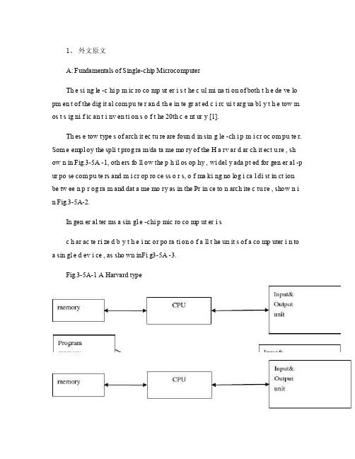
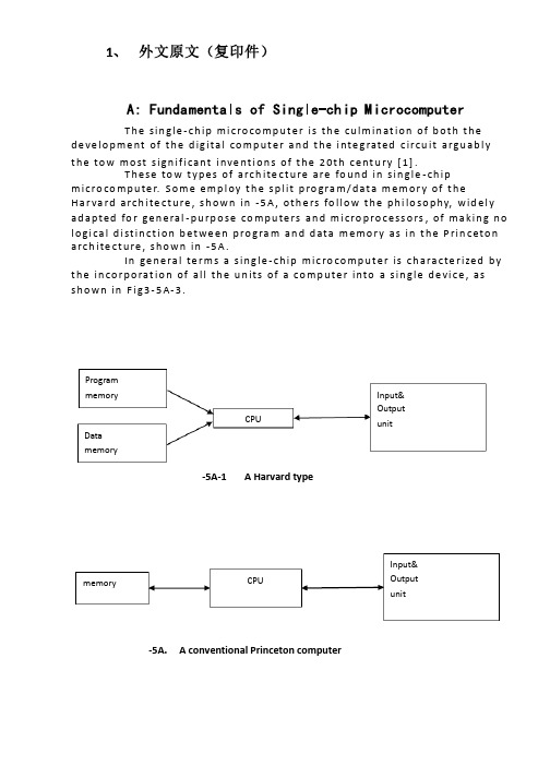
1、外文原文A: Fundamentals of Single-chip MicrocomputerTh e si ng le -c hi p m ic ro co mp ut er i s t he c ul mi na ti on of both t h e de ve lo pm en t of the dig it al com pu te r an d th e in te gr at ed c i rc ui t arg ua bl y t h e tow m os t s ig ni f ic an t i nv en ti on s o f t he 20th c e nt ur y [1].Th es e tow type s of arch it ec tu re are foun d in sin g le -ch i p m i cr oc om pu te r. Som e empl oy the spli t prog ra m/da ta me mo ry of the H a rv ar d ar ch it ect u re , sh ow n in Fig.3-5A -1, oth ers fo ll ow the p h il os op hy , wi del y ada pt ed for gen er al -p ur po se com pu te rs and m i cr op ro ce ss o r s, o f ma ki ng no log i ca l di st in ct ion be tw ee n p r og ra m and dat a me mo ry as in the Pr in ce to n arch ite c tu re , show n i n Fig.3-5A-2.In gen er al ter ms a sin gl e -chi p mic ro co mp ut er i sc h ar ac te ri zed b y t he i nc or po ra ti on of a ll t he un it s of a co mp uter i n to a sin gl e d ev i ce , as sho wn inFi g3-5A -3.Fig.3-5A-1 A Harvard typeFig.3-5A-2. A conventional Princeton computerFig3-5A-3. Principal features of a microcomputerRead only memory (ROM.R OM is usua ll y for the pe rm an ent,n o n-vo la ti le stor a ge of an app lic a ti on s pr og ra m .M an ym i cr oc om pu te rs and m are inte nd e d for high -v ol um e ap pl ic at ions a n d he nc e t h e eco n om ic al man uf act u re of th e de vic e s re qu ir es t h at t he cont en t s o f t he prog ra m me m or y be co mm it t ed perm a ne ntly d u ri ng the man ufa c tu re of ch ip s .Cl ea rl y, thi s im pl ie s a r i go ro us app ro ach to ROM cod e deve l op me nt sin ce cha ng es can not b e mad e afte r manu f a c tu re .Th is dev e lo pm en t proc ess may invo lv e e m ul at io n us in g aso ph is ti ca te d de ve lo pm en t sy ste m wit h a h a rd wa re emu la tio n cap ab il it y as w el l as the use o f po we rf ul s o ft wa re too ls.So me man uf act u re rs pro vi de add it io na l RO M opt i on s by i n cl ud in g in their ra n ge dev ic es wit h (or int en de d fo r use wit h u s er pro gr am ma ble me mo ry. Th e sim p le st of th es e is usu al ly d e vi ce whi ch can op er at e in a micro p ro ce ssor mod e by usi ng som e o f the inp ut /outp u t li ne s as an ad dr es s an d da ta b us fora c ce ss in g ex te rna l mem or y. Thi s t y pe of de vi ce can beh av ef u nc ti on al ly as th e sing le chip mi cr oc om pu te r from whi ch it is d e ri ve d al be it wit h re st ri ct ed I/O and a mod if ied ex te rn al c i rc ui t. The use of thes e d ev ic es is com mo n eve n in prod uc ti on c i rc ui ts wher e t he vo lu me does no tj us ti f y t h e d ev el o pm en t c osts o f c us to m o n -ch i p R OM [2];t he re c a n s ti ll bea s ignif i ca nt saving i n I /O and o th er c h ip s com pa re d to a conv en ti on al mi c ro pr oc es sor b a se d ci rc ui t. Mor e ex ac t re pl ace m en t fo r RO M dev i ce s ca n be o b ta in ed in th e fo rm of va ri an ts w it h 'p ig gy -b ack 'E P RO M(Er as ab le pro gr am ma bl e ROM s oc ke ts or dev ic e s with EPROM i n st ea d o f RO M 。
电气工程与自动化毕业论文中英文资料外文翻译
电气工程与自动化毕业论文中英文资料外文翻译The Transformer on load ﹠Introduction to DC MachinesIt has been shown that a primary input voltage 1V can be transformed to any desired open-circuit secondary voltage 2E by a suitable choice of turns ratio. 2E is available for circulating a load current impedance. For the moment, a lagging power factor will be considered. The secondary current and the resulting ampere-turns 22N I will change the flux, tending to demagnetize the core, reduce m Φ and with it 1E . Because the primary leakage impedance drop is so low, a small alteration to 1Ewill cause an appreciable increase of primary current from 0I to a new value of 1Iequal to ()()i jX R E V ++111/. The extra primary current and ampere-turns nearly cancel the whole of the secondary ampere-turns. This being so , the mutual flux suffers only a slight modification and requires practically the same net ampere-turns 10N I as on no load. The total primary ampere-turns are increased by an amount 22N I necessary to neutralize the same amount of secondary ampere-turns. In thevector equation , 102211N I N I N I =+; alternatively, 221011N I N I N I -=. At full load,the current 0I is only about 5% of the full-load current and so 1I is nearly equalto 122/N N I . Because in mind that 2121/N N E E =, the input kV A which is approximately 11I E is also approximately equal to the output kV A, 22I E .The physical current has increased, and with in the primary leakage flux towhich it is proportional. The total flux linking the primary ,111Φ=Φ+Φ=Φm p , isshown unchanged because the total back e.m.f.,(dt d N E /111Φ-)is still equal and opposite to 1V . However, there has been a redistribution of flux and the mutual component has fallen due to the increase of 1Φ with 1I . Although the change is small, the secondary demand could not be met without a mutual flux and e.m.f.alteration to permit primary current to change. The net flux s Φlinking thesecondary winding has been further reduced by the establishment of secondaryleakage flux due to 2I , and this opposes m Φ. Although m Φ and 2Φ are indicatedseparately , they combine to one resultant in the core which will be downwards at theinstant shown. Thus the secondary terminal voltage is reduced to dt d N V S /22Φ-=which can be considered in two components, i.e. dt d N dt d N V m //2222Φ-Φ-=orvectorially 2222I jX E V -=. As for the primary, 2Φ is responsible for a substantiallyconstant secondary leakage inductance222222/Λ=ΦN i N . It will be noticed that the primary leakage flux is responsible for part of the change in the secondary terminal voltage due to its effects on the mutual flux. The two leakage fluxes are closely related; 2Φ, for example, by its demagnetizing action on m Φ has caused the changes on the primary side which led to the establishment of primary leakage flux.If a low enough leading power factor is considered, the total secondary flux and the mutual flux are increased causing the secondary terminal voltage to rise with load. p Φ is unchanged in magnitude from the no load condition since, neglecting resistance, it still has to provide a total back e.m.f. equal to 1V . It is virtually the same as 11Φ, though now produced by the combined effect of primary and secondary ampere-turns. The mutual flux must still change with load to give a change of 1E and permit more primary current to flow. 1E has increased this time but due to the vector combination with 1V there is still an increase of primary current.Two more points should be made about the figures. Firstly, a unity turns ratio has been assumed for convenience so that '21E E =. Secondly, the physical picture is drawn for a different instant of time from the vector diagrams which show 0=Φm , if the horizontal axis is taken as usual, to be the zero time reference. There are instants in the cycle when primary leakage flux is zero, when the secondary leakage flux is zero, and when primary and secondary leakage flux is zero, and when primary and secondary leakage fluxes are in the same sense.The equivalent circuit already derived for the transformer with the secondary terminals open, can easily be extended to cover the loaded secondary by the addition of the secondary resistance and leakage reactance.Practically all transformers have a turns ratio different from unity although such an arrangement is sometimes employed for the purposes of electrically isolating one circuit from another operating at the same voltage. To explain the case where 21N N ≠ the reaction of the secondary will be viewed from the primary winding. The reaction is experienced only in terms of the magnetizing force due to the secondary ampere-turns. There is no way of detecting from the primary side whether 2I is large and 2N small or vice versa, it is the product of current and turns which causesthe reaction. Consequently, a secondary winding can be replaced by any number of different equivalent windings and load circuits which will give rise to an identical reaction on the primary .It is clearly convenient to change the secondary winding to an equivalent winding having the same number of turns 1N as the primary.With 2N changes to 1N , since the e.m.f.s are proportional to turns, 2212)/('E N N E = which is the same as 1E .For current, since the reaction ampere turns must be unchanged 1222'''N I N I = must be equal to 22N I .i.e. 2122)/(I N N I =.For impedance , since any secondary voltage V becomes V N N )/(21, and secondary current I becomes I N N )/(12, then any secondary impedance, including load impedance, must becomeI V N N I V /)/('/'221=. Consequently,22212)/('R N N R = and 22212)/('X N N X = . If the primary turns are taken as reference turns, the process is called referring to the primary side.There are a few checks which can be made to see if the procedure outlined is valid.For example, the copper loss in the referred secondary winding must be the same as in the original secondary otherwise the primary would have to supply a differentloss power. ''222R I must be equal to 222R I . )222122122/()/(N N R N N I •• does infact reduce to 222R I .Similarly the stored magnetic energy in the leakage field)2/1(2LI which is proportional to 22'X I will be found to check as ''22X I . The referred secondary 2212221222)/()/(''I E N N I N N E I E kVA =•==.The argument is sound, though at first it may have seemed suspect. In fact, if the actual secondary winding was removed physically from the core and replaced by the equivalent winding and load circuit designed to give the parameters 1N ,'2R ,'2X and '2I , measurements from the primary terminals would be unable to detect any difference in secondary ampere-turns, kVA demand or copper loss, under normal power frequency operation.There is no point in choosing any basis other than equal turns on primary andreferred secondary, but it is sometimes convenient to refer the primary to the secondary winding. In this case, if all the subscript 1’s are interchanged for the subscript 2’s, the necessary referring constants are easily found; e.g. 2'1R R ≈,21'X X ≈; similarly 1'2R R ≈ and 12'X X ≈.The equivalent circuit for the general case where 21N N ≠ except that m r hasbeen added to allow for iron loss and an ideal lossless transformation has been included before the secondary terminals to return '2V to 2V .All calculations of internal voltage and power losses are made before this ideal transformation is applied. The behaviour of a transformer as detected at both sets of terminals is the same as the behaviour detected at the corresponding terminals of this circuit when the appropriate parameters are inserted. The slightly different representation showing the coils 1N and 2N side by side with a core in between is only used for convenience. On the transformer itself, the coils are , of course , wound round the same core.Very little error is introduced if the magnetising branch is transferred to the primary terminals, but a few anomalies will arise. For example ,the current shown flowing through the primary impedance is no longer the whole of the primary current.The error is quite small since 0I is usually such a small fraction of 1I . Slightlydifferent answers may be obtained to a particular problem depending on whether or not allowance is made for this error. With this simplified circuit, the primary and referred secondary impedances can be added to give:221211)/(Re N N R R += and 221211)/(N N X X Xe +=It should be pointed out that the equivalent circuit as derived here is only valid for normal operation at power frequencies; capacitance effects must be taken into account whenever the rate of change of voltage would give rise to appreciablecapacitance currents, dt CdV I c /=. They are important at high voltages and atfrequencies much beyond 100 cycles/sec. A further point is not the only possible equivalent circuit even for power frequencies .An alternative , treating the transformer as a three-or four-terminal network, gives rise to a representation which is just as accurate and has some advantages for the circuit engineer who treats all devices as circuit elements with certain transfer properties. The circuit on this basiswould have a turns ratio having a phase shift as well as a magnitude change, and the impedances would not be the same as those of the windings. The circuit would not explain the phenomena within the device like the effects of saturation, so for an understanding of internal behaviour .There are two ways of looking at the equivalent circuit:(a) viewed from the primary as a sink but the referred load impedance connected across '2V ,or(b) viewed from the secondary as a source of constant voltage 1V with internal drops due to 1Re and 1Xe . The magnetizing branch is sometimes omitted in this representation and so the circuit reduces to a generator producing a constant voltage 1E (actually equal to 1V ) and having an internal impedance jX R + (actually equal to 11Re jXe +).In either case, the parameters could be referred to the secondary winding and this may save calculation time .The resistances and reactances can be obtained from two simple light load tests. Introduction to DC MachinesDC machines are characterized by their versatility. By means of various combination of shunt, series, and separately excited field windings they can be designed to display a wide variety of volt-ampere or speed-torque characteristics for both dynamic and steadystate operation. Because of the ease with which they can be controlled , systems of DC machines are often used in applications requiring a wide range of motor speeds or precise control of motor output.The essential features of a DC machine are shown schematically. The stator has salient poles and is excited by one or more field coils. The air-gap flux distribution created by the field winding is symmetrical about the centerline of the field poles. This axis is called the field axis or direct axis.As we know , the AC voltage generated in each rotating armature coil is converted to DC in the external armature terminals by means of a rotating commutator and stationary brushes to which the armature leads are connected. The commutator-brush combination forms a mechanical rectifier, resulting in a DCarmature voltage as well as an armature m.m.f. wave which is fixed in space. The brushes are located so that commutation occurs when the coil sides are in the neutral zone , midway between the field poles. The axis of the armature m.m.f. wave then in 90 electrical degrees from the axis of the field poles, i.e., in the quadrature axis. In the schematic representation the brushes are shown in quarature axis because this is the position of the coils to which they are connected. The armature m.m.f. wave then is along the brush axis as shown.. (The geometrical position of the brushes in an actual machine is approximately 90 electrical degrees from their position in the schematic diagram because of the shape of the end connections to the commutator.)The magnetic torque and the speed voltage appearing at the brushes are independent of the spatial waveform of the flux distribution; for convenience we shall continue to assume a sinusoidal flux-density wave in the air gap. The torque can then be found from the magnetic field viewpoint.The torque can be expressed in terms of the interaction of the direct-axis air-gapflux per pole d Φ and the space-fundamental component 1a F of the armature m.m.f.wave . With the brushes in the quadrature axis, the angle between these fields is 90 electrical degrees, and its sine equals unity. For a P pole machine 12)2(2a d F P T ϕπ=In which the minus sign has been dropped because the positive direction of thetorque can be determined from physical reasoning. The space fundamental 1a F ofthe sawtooth armature m.m.f. wave is 8/2π times its peak. Substitution in above equation then givesa d a a d a i K i m PC T ϕϕπ==2 Where a i =current in external armature circuit;a C =total number of conductors in armature winding;m =number of parallel paths through winding;Andm PC K aa π2=Is a constant fixed by the design of the winding.The rectified voltage generated in the armature has already been discussedbefore for an elementary single-coil armature. The effect of distributing the winding in several slots is shown in figure ,in which each of the rectified sine waves is the voltage generated in one of the coils, commutation taking place at the moment when the coil sides are in the neutral zone. The generated voltage as observed from the brushes is the sum of the rectified voltages of all the coils in series between brushesand is shown by the rippling line labeled a e in figure. With a dozen or socommutator segments per pole, the ripple becomes very small and the average generated voltage observed from the brushes equals the sum of the average values ofthe rectified coil voltages. The rectified voltage a e between brushes, known also asthe speed voltage, ism d a m d a a W K W m PC e ϕϕπ==2 Where a K is the design constant. The rectified voltage of a distributed winding has the same average value as that of a concentrated coil. The difference is that the ripple is greatly reduced.From the above equations, with all variable expressed in SI units:m a a Tw i e =This equation simply says that the instantaneous electric power associated with the speed voltage equals the instantaneous mechanical power associated with the magnetic torque , the direction of power flow being determined by whether the machine is acting as a motor or generator.The direct-axis air-gap flux is produced by the combined m.m.f. f f i N ∑ of the field windings, the flux-m.m.f. characteristic being the magnetization curve for the particular iron geometry of the machine. In the magnetization curve, it is assumed that the armature m.m.f. wave is perpendicular to the field axis. It will be necessary to reexamine this assumption later in this chapter, where the effects of saturation are investigated more thoroughly. Because the armature e.m.f. is proportional to flux times speed, it is usually more convenient to express the magnetization curve in termsof the armature e.m.f. 0a e at a constant speed 0m w . The voltage a e for a given fluxat any other speed m w is proportional to the speed,i.e. 00a m m a e w w e =Figure shows the magnetization curve with only one field winding excited. This curve can easily be obtained by test methods, no knowledge of any design details being required.Over a fairly wide range of excitation the reluctance of the iron is negligible compared with that of the air gap. In this region the flux is linearly proportional to the total m.m.f. of the field windings, the constant of proportionality being the direct-axis air-gap permeance.The outstanding advantages of DC machines arise from the wide variety of operating characteristics which can be obtained by selection of the method of excitation of the field windings. The field windings may be separately excited from an external DC source, or they may be self-excited; i.e., the machine may supply its own excitation. The method of excitation profoundly influences not only the steady-state characteristics, but also the dynamic behavior of the machine in control systems.The connection diagram of a separately excited generator is given. The required field current is a very small fraction of the rated armature current. A small amount of power in the field circuit may control a relatively large amount of power in the armature circuit; i.e., the generator is a power amplifier. Separately excited generators are often used in feedback control systems when control of the armature voltage over a wide range is required. The field windings of self-excited generators may be supplied in three different ways. The field may be connected in series with the armature, resulting in a shunt generator, or the field may be in two sections, one of which is connected in series and the other in shunt with the armature, resulting in a compound generator. With self-excited generators residual magnetism must be present in the machine iron to get the self-excitation process started.In the typical steady-state volt-ampere characteristics, constant-speed primemovers being assumed. The relation between the steady-state generated e.m.f. a Eand the terminal voltage t V isa a a t R I E V -=Where a I is the armature current output and a R is the armature circuitresistance. In a generator, a E is large than t V ; and the electromagnetic torque T is acountertorque opposing rotation.The terminal voltage of a separately excited generator decreases slightly with increase in the load current, principally because of the voltage drop in the armature resistance. The field current of a series generator is the same as the load current, so that the air-gap flux and hence the voltage vary widely with load. As a consequence, series generators are not often used. The voltage of shunt generators drops off somewhat with load. Compound generators are normally connected so that the m.m.f. of the series winding aids that of the shunt winding. The advantage is that through the action of the series winding the flux per pole can increase with load, resulting in a voltage output which is nearly constant. Usually, shunt winding contains many turns of comparatively heavy conductor because it must carry the full armature current of the machine. The voltage of both shunt and compound generators can be controlled over reasonable limits by means of rheostats in the shunt field. Any of the methods of excitation used for generators can also be used for motors. In the typical steady-state speed-torque characteristics, it is assumed that the motor terminals are supplied froma constant-voltage source. In a motor the relation between the e.m.f. a E generated inthe armature and the terminal voltage t V isa a a t R I E V +=Where a I is now the armature current input. The generated e.m.f. a E is nowsmaller than the terminal voltage t V , the armature current is in the oppositedirection to that in a motor, and the electromagnetic torque is in the direction to sustain rotation of the armature.In shunt and separately excited motors the field flux is nearly constant. Consequently, increased torque must be accompanied by a very nearly proportional increase in armature current and hence by a small decrease in counter e.m.f. to allow this increased current through the small armature resistance. Since counter e.m.f. is determined by flux and speed, the speed must drop slightly. Like the squirrel-cage induction motor ,the shunt motor is substantially a constant-speed motor having about 5 percent drop in speed from no load to full load. Starting torque and maximum torque are limited by the armature current that can be commutatedsuccessfully.An outstanding advantage of the shunt motor is ease of speed control. With a rheostat in the shunt-field circuit, the field current and flux per pole can be varied at will, and variation of flux causes the inverse variation of speed to maintain counter e.m.f. approximately equal to the impressed terminal voltage. A maximum speed range of about 4 or 5 to 1 can be obtained by this method, the limitation again being commutating conditions. By variation of the impressed armature voltage, very wide speed ranges can be obtained.In the series motor, increase in load is accompanied by increase in the armature current and m.m.f. and the stator field flux (provided the iron is not completely saturated). Because flux increases with load, speed must drop in order to maintain the balance between impressed voltage and counter e.m.f.; moreover, the increase in armature current caused by increased torque is smaller than in the shunt motor because of the increased flux. The series motor is therefore a varying-speed motor with a markedly drooping speed-load characteristic. For applications requiring heavy torque overloads, this characteristic is particularly advantageous because the corresponding power overloads are held to more reasonable values by the associated speed drops. Very favorable starting characteristics also result from the increase in flux with increased armature current.In the compound motor the series field may be connected either cumulatively, so that its.m.m.f.adds to that of the shunt field, or differentially, so that it opposes. The differential connection is very rarely used. A cumulatively compounded motor has speed-load characteristic intermediate between those of a shunt and a series motor, the drop of speed with load depending on the relative number of ampere-turns in the shunt and series fields. It does not have the disadvantage of very high light-load speed associated with a series motor, but it retains to a considerable degree the advantages of series excitation.The application advantages of DC machines lie in the variety of performance characteristics offered by the possibilities of shunt, series, and compound excitation. Some of these characteristics have been touched upon briefly in this article. Stillgreater possibilities exist if additional sets of brushes are added so that other voltages can be obtained from the commutator. Thus the versatility of DC machine systems and their adaptability to control, both manual and automatic, are their outstanding features.中文翻译负载运行的变压器及直流电机导论通过选择合适的匝数比,一次侧输入电压1V 可任意转换成所希望的二次侧开路电压2E 。
电气工程及其自动化专业 外文文献 英文文献 外文翻译 plc方面

1、外文原文(复印件)A: Fundamentals of Single-chip MicrocomputerTh e si ng le-ch i p mi cr oc om pu ter is t he c ul mi nat i on o f bo th t h e d ev el op me nt o f th e d ig it al com p ut er an d t he int e gr at ed ci rc ui ta r gu ab ly th e t ow m os t s i gn if ic ant i nv en ti on s o f t h e 20t h c en tu ry[1].Th es e to w typ e s of a rc hi te ctu r e ar e fo un d i n s in gl e-ch ip m i cr oc om pu te r. So m e em pl oy t he sp l it p ro gr am/d ata me mo ry o f th e H a rv ar d ar ch it ect u re, sh ow n i n -5A, ot he rs fo ll ow th e ph i lo so ph y, w i de ly a da pt ed fo r g en er al-p ur pos e c om pu te rs an d m i cr op ro ce ss or s, o f m a ki ng no lo gi c al di st in ct io n b e tw ee n p ro gr am a n d da t a m em ory a s i n th e Pr in cet o n ar ch it ec tu re,sh ow n in-5A.In g en er al te r ms a s in gl e-chi p m ic ro co mp ut er i sc h ar ac te ri zed b y the i nc or po ra tio n of al l t he uni t s o f a co mp ut er i n to a s in gl e dev i ce, as s ho wn in Fi g3-5A-3.-5A-1 A Harvard type-5A. A conventional Princeton computerFig3-5A-3. Principal features of a microcomputerRead only memory (ROM).R OM i s u su al ly f or th e p er ma ne nt, n o n-vo la ti le s tor a ge o f an a pp lic a ti on s pr og ra m .M an ym i cr oc om pu te rs an d mi cr oc on tr ol le r s a re in t en de d fo r h ig h-v ol ume a p pl ic at io ns a nd h en ce t he e co nom i ca l ma nu fa ct ure of t he d ev ic es r e qu ir es t ha t the co nt en ts o f the pr og ra m me mo ry b e co mm it te dp e rm an en tl y d ur in g th e m an uf ac tu re o f c hi ps . Cl ear l y, th is im pl ie sa ri g or ou s a pp roa c h t o R OM co de d e ve lo pm en t s in ce c ha ng es ca nn otb e m ad e af te r man u fa ct ur e .T hi s d e ve lo pm en t pr oce s s ma y in vo lv e e m ul at io n us in g a s op hi st ic at ed deve lo pm en t sy st em w i th a ha rd wa re e m ul at io n ca pa bil i ty a s we ll a s th e u se of po we rf ul so ft wa re t oo ls.So me m an uf act u re rs p ro vi de ad d it io na l RO M opt i on s byi n cl ud in g i n th ei r ra ng e de vi ce s wi th (or i nt en de d fo r us e wi th) u s er pr og ra mm ab le m em or y. Th e s im p le st of th es e i s us ua ll y d ev ice w h ic h ca n op er ate in a m ic ro pr oce s so r mo de b y usi n g so me o f th e i n pu t/ou tp ut li ne s as a n ad dr es s an d da ta b us f or acc e ss in g e xt er na l m e mo ry. T hi s t ype o f d ev ic e c an b e ha ve fu nc ti on al l y a s t he si ng le c h ip mi cr oc om pu te r fr om wh ic h i t i s de ri ve d a lb eit w it h r es tr ic ted I/O an d a mo di fie d e xt er na l ci rcu i t. T he u se o f t h es e RO Ml es sd e vi ce s is c om mo n e ve n in p ro du ct io n c ir cu it s wh er e t he v ol um e do es n o t ju st if y th e d e ve lo pm en t co sts of c us to m on-ch i p RO M[2];t he re c a n st il l b e a si g ni fi ca nt s a vi ng in I/O a nd ot he r c hi ps co mp ar ed t o a c on ve nt io nal mi cr op ro ce ss or b as ed c ir cu it. M o re e xa ctr e pl ac em en t fo r RO M d ev ic es c an b e o bt ai ne d in t he f o rm o f va ri an ts w i th 'pi gg y-ba ck'EP RO M(Er as ab le p ro gr am ma bl e ROM)s oc ke ts o rd e vi ce s w it h EP ROM i ns te ad o f R OM 。
电气工程及其自动化专业外文文献英文文献外文翻译方面
1、 外文原文(复印件)A: Fundamentals of Single-chip MicrocomputerT h e sin gle -ch ip mi c ro co m p u t e r is t h e cu lm in at io n of b ot h t h e d e ve lo p me nt of t h e d ig ita l co m p u t e r a n d t h e i nte g rated c ircu it a rgu ab l y t h e to w mo st s ign if i cant i nve nt i o n s of t h e 20t h c e nt u ry [1].T h ese to w t yp e s of arch ite ct u re are fo u n d in s in gle -ch ip m i cro co m p u te r. S o m e e mp l oy t h e sp l it p ro gra m /d at a m e m o r y of t h e H a r va rd arch ite ct u re , s h o wn in -5A , ot h e rs fo l lo w t h e p h i lo so p hy, wid e l y ad a p ted fo r ge n e ral -p u rp o se co m p u te rs an d m i cro p ro ce ss o rs , of m a kin g n o l o g i ca l d i st in ct i o n b et we e n p ro gra m an d d ata m e m o r y as in t h e P rin c eto n a rch ite ct u re , sh o wn in -5A.In ge n e ra l te r m s a s in g le -ch ip m ic ro co m p u t e r is ch a ra cte r ized b y t h e in co r p o rat io n of all t h e u n its of a co mp u te r into a s in gle d e vi ce , as s h o w n in F i g3-5A-3.-5A-1A Harvard type-5A. A conventional Princeton computerProgrammemory Datamemory CPU Input& Output unitmemoryCPU Input& Output unitResetInterruptsPowerFig3-5A-3. Principal features of a microcomputerRead only memory (ROM).RO M is u su a l l y fo r t h e p e r m an e nt , n o n -vo lat i le sto rage of an ap p l i cat io n s p ro g ram .M a ny m i c ro co m p u te rs a n d m i cro co nt ro l le rs are inte n d ed fo r h i gh -vo lu m e ap p l i cat io n s a n d h e n ce t h e e co n o m i cal man u fa c t u re of t h e d e vi ces re q u ires t h at t h e co nt e nts of t h e p ro gra m me mo r y b e co mm i ed p e r m a n e nt l y d u r in g t h e m a n u fa ct u re of c h ip s . C lea rl y, t h i s imp l ies a r i go ro u s ap p ro a ch to ROM co d e d e ve lo p m e nt s in ce ch an ges can n o t b e mad e af te r m an u fa ct u re .T h i s d e ve l o p m e nt p ro ces s m ay i nvo l ve e mu l at i o n u sin g a so p h ist icated d e ve lo p m e nt syste m wit h a h ard wa re e mu l at i o n capab i l it y as we ll as t h e u s e of p o we rf u l sof t war e to o l s.So m e m an u fa ct u re rs p ro vi d e ad d it i o n a l ROM o p t io n s b y in clu d in g in t h e i r ran ge d e v ic es w it h (o r inte n d ed fo r u s e wit h ) u se r p ro g ram m a b le m e mo r y. T h e s im p lest of t h e se i s u su a l l y d e v i ce wh i ch can o p e rat e in a m i cro p ro ce s so r mo d e b y u s in g s o m e of t h e in p u t /o u t p u t l in es as an ad d res s a n d d ata b u s fo r a cc es sin g exte rn a l m e m o r y. T h is t yp e o f d e vi ce can b e h ave f u n ct i o n al l y as t h e s in gle ch ip m i cro co m p u t e r f ro m wh i ch it i s d e ri ved a lb e it wit h re st r icted I/O an d a m o d if ied exte rn a l c ircu it. T h e u s e of t h e se RO M le ss d e vi ces i s co mmo n e ve n in p ro d u ct io n circu i ts wh e re t h e vo lu m e d o e s n ot ju st if y t h e d e ve lo p m e nt co sts of cu sto m o n -ch ip ROM [2];t h e re ca n st i ll b e a si gn if i cant sav in g in I/O an d o t h e r ch ip s co m pared to a External Timing components System clock Timer/ Counter Serial I/O Prarallel I/O RAM ROMCPUco nve nt io n al m i c ro p ro ces so r b ased circ u it. M o re exa ct re p l a ce m e nt fo rRO M d e v ice s can b e o b tain ed in t h e fo rm of va ria nts w it h 'p i g g y-b a c k'E P ROM(E rasab le p ro gramm ab le ROM )s o cket s o r d e v ice s w it h E P ROMin stead of ROM 。
电气专业毕业设计外文翻译---电力系统自动化
外文资料翻译Power System AutomationPower system integration is the act of communication data to, or among IED s in the I&C system and remote users. Substation integration refers to combining data from the IED′s local to a substation so that there is a single point of contact in the substation for all of the I&C data. Poletop devices often communicate to the substation via wireless or fiber connections. Remote and local substation and feeder control is passed through the substation controller acting as a single point of contact. Some systems bypass the substation controller by using direct connections to the poletop devices, such as RTU s, protective relays, and controllers.Power system automation is the act of automatically controlling the power system via I&C devices. Substation automation refers to using IED data, control and automation capabilities within the substation, and control commands from remote users to control power system devices. Since true substation automation relies on substation integration, the terms are often used interchangeably.Power system automation includes processes associated with generation and delivery of power. A subset of the process deal with delivery of power at transmission and distribution levels, which is power delivery automation. Together, monitoring and control of power delivery system in the substation and on the poletop reduce the occurrence of outages and shorten the duration of outages that do occur. The IED′s, communications protocols, and communications methods described in previous sections, work together as a system to perform power system automation.Though each utility is unique, most consider power delivery automation of transmission and distribution substation and feeders to include : Supervisory Control and Data Acquisition(SCADA)-operatorsupervision and control;Distribution Automation-fault location, auto-isolation, auto-sectionalizing, and auto-restoration;Substation Automation-breaker failure, reclosing, battery monitoring, dead substation transfer, and substation load transfer;Energy Management System (EMS)-load flow, VAR and voltage monitoring and control, generation control, transformer and feeder load balancing;Fault analysis and device maintenance.System without automated control still have the advantages of remote monitoring and operator control of power system devices, which includes: Remote monitoring and control of circuit breakers and automated switches;Remote monitoring of non-automated switches and fuses;Remote monitoring and control of capacitor banks;Remote monitoring and voltage control;Remote power quality monitoring and control.IED s described in the overview are used to perform power system integration and automation. Most designs require that the one IED act as the substation controller and perform data acquisition and control of the other IED s. The substation controllers is often called upon to support system automation tasks as well. The communications industry uses the term client/server for a device that acts as a master, or client, retrieving data from some devices and then acts as a slaver, a server, sending this data to other devices. The client/server collecting and concentrating dynamically. A data concentrator creates a substation databases by collecting and concentrating dynamic data from several devices. In this fashion, essential subsets of data from each IED are forwarded to a master through one data transfer. The concentrator databases is used to pass data between IED s that are not directly connected.A substation archive client/server collects and archives data from several devices. The archive data is retrieved when it is convenient for the userto do so.The age of the IED s now in substations varies widely. Many of these IED s are still useful but lack the most recent protocols. A communications processor that can communicate with each IED via a unique baud rate and protocol extends the time that each IED is useful. Using a communications processor for substation integration also easily accommodates future IED s. It is rare for all existing IED s to be discarded during a substation integration upgrade project.The benefits of monitoring, remote control, and automation of power delivery include improved employee and public safety, and deferment of the cost of purchasing new equipment. Also, reduced operation and maintenance costs are realized through improved use of existing facilities and optimized performance of the power system through reduced losses associated with outages and improved voltage profile. Collection of information can result in better planning and system design, and increased customer satisfaction will result from improved responsiveness, service reliability, and power quality.Power system automation includes a variety of equipment. The principal items are listed and briefly described below.Instrument transformers are used to sense power system current and voltage. They are physically connected to power system apparatus and convert the actual power system signals, which includes high voltage and current magnitudes, down to lower signal levels.Transducers convert the analog output of an instrument transformer from one magnitude to another or from one value type to another, such as from an ac current to dc voltage.As the name implies, a remote terminal device, RTU, is an IED that can be installed in a remote location, and acts as a termination point for filed contacts. A dedicated pair of copper conductors are used to sense every contract and transducer value. These conductors originated at the power system device, are installed in trenches or overhead cable trays, and are thenterminated on panels within the RTU. The RTU can transfer collected data to other devices and receive data and control commands from other device through a serial port. User programmable RTUs are referred to as “smart RTUs.”A communication switch is a device that switches between several serial ports when it is told to do so. The remote user initiates communications with the port switch via a connection to the substation , typically a leased line or dial-up telephone connection. Once connected, the user can route their communication through the port switch to one of the connected substation IEDs. The port switch merely “passes through” the IED communication.A meter is an IED that is used to create accurate measurement of power system current, voltage, and power values. Metering values such as demand and peak are saved within the meter to create historical information about the activity of the power system.A digital fault recorder ,is an IED that records information about power system disturbances. It is capable of storing data in digital format when triggered by conditions detected on the power system. Harmonics, frequency, and voltage are examples of data captured by DFRs.Load tap changer are devices used to change the tap position on transformers. These devices work automatically or can be controlled via another local IED or form a remote operator or process.Recloser controllers remotely control the operation of automated reclosers and switches. These devices monitor and store power system conditions and determine when to perform control actions. They also accept commands form a remote operator or process.电力系统自动化电力系统集成是在I&C系统中的IED和远程用户之间进行数据通信的操作。
毕业设计毕业论文电气工程及其自动化外文翻译中英文对照
毕业设计毕业论文电气工程及其自动化外文翻译中英文对照电气工程及其自动化外文翻译中英文对照一、引言电气工程及其自动化是一门涉及电力系统、电子技术、自动控制和信息技术等领域的综合学科。
本文将翻译一篇关于电气工程及其自动化的外文文献,并提供中英文对照。
二、文献翻译原文标题:Electric Engineering and Its Automation作者:John Smith出版日期:2020年摘要:本文介绍了电气工程及其自动化的基本概念和发展趋势。
首先,介绍了电气工程的定义和范围。
其次,探讨了电气工程在能源领域的应用,包括电力系统的设计和运行。
然后,介绍了电气工程在电子技术领域的重要性,包括电子设备的设计和制造。
最后,讨论了电气工程与自动控制和信息技术的结合,以及其在工业自动化和智能化领域的应用。
1. 介绍电气工程是一门研究电力系统和电子技术的学科,涉及发电、输电、配电和用电等方面。
电气工程的发展与电力工业的发展密切相关。
随着电力需求的增长和电子技术的进步,电气工程的重要性日益凸显。
2. 电气工程在能源领域的应用电气工程在能源领域的应用主要包括电力系统的设计和运行。
电力系统是由发电厂、输电线路、变电站和配电网络等组成的。
电气工程师负责设计和维护这些设施,以确保电力的可靠供应。
3. 电气工程在电子技术领域的重要性电气工程在电子技术领域的重要性体现在电子设备的设计和制造上。
电子设备包括电脑、手机、电视等消费电子产品,以及工业自动化设备等。
电气工程师需要掌握电子电路设计和数字信号处理等技术,以开发出高性能的电子设备。
4. 电气工程与自动控制和信息技术的结合电气工程与自动控制和信息技术的结合是电气工程及其自动化的核心内容。
自动控制技术可以应用于电力系统的运行和电子设备的控制,以提高系统的稳定性和效率。
信息技术则可以用于数据采集、处理和传输,实现对电力系统和电子设备的远程监控和管理。
5. 电气工程在工业自动化和智能化领域的应用电气工程在工业自动化和智能化领域的应用越来越广泛。
电气自动化 单片机 外文文献 英文文献 外文翻译 中英对照
Single-chip1.The definition of a single-chipSingle-chip is an integrated on a single chip a complete computer system .Even though most of his features in a small chip,but it has a need to complete the majority of computer components:CPU,memory,internal and external bus system,most will have the Core.At the same time,such as integrated communication interfaces,timers,real-time clock and other peripheral equipment.And now the most powerful single-chip microcomputer system can even voice ,image,networking,input and output complex system integration on a single chip.Also known as single-chip MCU(Microcontroller),because it was first used in the field of industrial control.Only by the single-chip CPU chip developed from the dedicated processor. The design concept is the first by a large numberof peripherals and CPU in a single chip,the computer system so that smaller,more easily integrated into the complex and demanding on the volume control devices.INTEL the Z80 is one of the first design in accordance with the idea of the processor,From then on,the MCU and the development of a dedicated processor parted ways.Early single-chip 8-bit or all the four.One of the most successful is INTELs 8031,because the performance of a simple and reliable access to a lot of good praise.Since then in 8031to develop a single-chip microcomputer system MCS51 series.based on single-chip microcomputer system of the system is still widely used until now.As the field of industrial control requirements increase in the beginning of a 16-bit single-chip,but not ideal because the price has not been very widely used.After the90s with the big consumer electronics product development,single-chip technology is a huge improvement.INTEL i960 series with subsequent ARM in particular ,a broad range of application,quickly replaced by 32-bit single-chip 16-bit single-chip performance has been the rapid increase in processing power compared to the 80s to raise a few hundred times.At present,the high-end 32-bit single-chip frequency over 300MHz,the performance of the mid-90s close on the heels of a special processor,while the ordinary price of the model dropped to one U.S dollars,the most high-end models,only 10 U.S dollars.Contemporary single-chip microcomputer system is no longer only the bare-metal environment in the development and use of a large number of dedicated embedded operating system is widely used in the full range of single-chip microcomputer.In PDAs and cellphones as the coreprocessing of high-end single-chip or even a dedicated direct access to Windows and Linux operating systems.More than a dedicated single-chip processor suitable for embedded systems,so it was up to the application.In fact the number of single-chip is the worlds largest computer.Modern human life used in almost every piece of electronic and mechanical products will have a single-chip integration.Phone,telephone,calculator,home applicances,electronic toys,handheld computers and computer accessories such as a mouse in the Department are equipped with 1-2 single chip.And personal computers also have a large number of single-chip microcomputer in the workplace.Vehicles equipped with more than 40 Department of the general single-chip ,complex industrial control systems and even single-chip may have hundreds of work at the same time!SCM is not only far exceeds the number of PC and other integrated computing,even more than the number of human beings.2.single-chip introducedSingle-chip,also known as single-chip microcontroller,it is not the completion of a logic function of the chip,but a computer system integrated into a chip.Speaking in general terms: a single chip has become a computer .Its small size,light weight,cheap,for the learning,application and development of facilities provided .At the same time,learning to use the principle of single-chip computer to understand and structure the best choice.Single-chip and computer use is also similar to the module,such as CPU,memory,parallel bus, as well as the role and the same hard memory,is it different from the performance of these components are relatively weak in our home computer a lot,but the price is low ,there is generally no more than 10yuan,,can use it to make some control for a class of electrical work is not very complex is sufficient.We are using automatic drum washing machines, smoke hood,VCD and so on inside the home appliances can see its shadow! It is mainly as part of the core components of the control.It is an online real-time control computer,control-line is at the scene,we need to have a stronger anti-interference ability,low cost,and this is off-line computer(such as home PC)The main difference.By single-chip process,and can be amended.Through different procedures to achieve different functions,in particular the special unique features,this is the need to charge other devices can do a great effort,some of it is also difficult to make great efforts to do so .A function is not very complicated fi the United States the development of the 50s series of 74 or 60 during the CD4000series to get these pure hardware,the circuit must be a big PCB board !However,if the United States if the successful 70s seriesof single-chip market ,the result will be different!Simply because the adoption of single-chip preparation process you can achieve high intelligence,high efficiency and high reliability!Because of cost of single-chip is sensitive,so the dominant software or the lowest level assembly language,which is in addition to the lowest level for more than binary machine code of the language ,since such a low-level so why should we use ?Many of the seniors language has reached a level of visual programming why is it not in use ?The reason is simple ,that is,single-chip computer as there is no home of CPU,also not as hard as the mass storage device.A visualization of small high-level language program,even if there is only one button which will reach the size of dozens of K! For the home PCs hard drive is nothing,but in terms of the single-chip microcomputer is unacceptable.Single-chip in the utilization of hardware resources have to do very high ,so the compilation of the original while still in heavy use .The same token ,if the computer giants operating system and appplications run up to get the home PC,homePCcan not afford to sustain the same.It can be said that the twentieth century across the three “power”of the times,that is ,the electrical era,the electronic age and has now entered the computer age. However ,such a computer,usually refers to a personal computer,or PC.It consisits of the host ,keyboards,displays .And other components.There is also a type of computer,not how most people are familiar with . This computer is smart to give a variety of mechanical single-chip(also known as micro-controller).As the name suggests,these computer systems use only the minimum of an integrated circuit to make a simple calculation and control. Because of its small size,are usually charged with possession of machine in the “belly”in. It in the device,like the human mind plays a role, it is wrong,the entire device was paralyzed .Now,this single chip has a very wide field of use,such as smart meters,real-time industrial control,communications equipment,navigation systems,and household appliances. Once a variety of products with the use of the single-chip ,will be able to play so that the effectiveness of product upgrading,product names often adjective before the word “intelligent”,such as was hing machines and so intelligent.At present,some technical personnel of factories or other amateur electrtonics developers from engaging in certain products ,not the circuit is too complex ,that is functional and easy to be too simple imitation.The reason may be the product not on the cards or the use of single-chip programmable logic device on the other.3.single-chip historysingle-chip 70 was born in the late 20th century,experienced a SCM,MCU,SOC three stages.Single-chip micro-computer 1.SCM that(Single Chip Microcomputer)stage,is mainly a single from to find the best of the best embedded systems architecture.”Innovation model”to be successful,lay the SCM with the general-purpose computers,a completely different path of development . In embedded systems to create an independent development path,Intel Corporation credit.That is 2.MCU microcontroller(Micro Controller Unit)stage,the main direction of technology development: expanding to meet the embedded applications,the target system requirements for the various peripheral circuits and interface circuits,to highlingt the target of intelligent control.It covers all areas related with the objectSystem,therefore,the development of MCU inevitably fall on the heavy electrical,electronics manufacturers. From this point of view ,Intels development gradually MCU has its objective factors.MCU in the development ,the most famous manufacturers when the number of Philips Corporation.Philips in embedded applications for its enormous advantages,the MCS-51 from the rapid deveploment of single-chip micro-computer to the microcontroller.Therefore,when we look back at the path of development of embedded systems,Intel and Philips do not forget the historical merits.3.Single-chip is an independent embedded systems development,to the MCU an important factor in the development stage,is seeking applications to maximize the natural trend .With the mico-electronics technology,IC design,EDA tools development,based on the single-chip SOC design application systems will have greater development. Therefore,the understanding of single-chip micro-computer from a single ,monolithic single-chip microcontroller extends to applications.4.Single-chip applicationsAt present,single-chip microcomputer to infiltrate all areas of our lives,which is very difficult to find the area of almost no traces of single-chip microcomputer.Missile navigation equipment,aircraft control on a variety of instruments,compuer network communications and data transmission,industrial automation,real-time process control and data processing ,are widely used in a variety of smart IC card,limousine civilian security systems,video recorders,cameras,the control of automatic washing machines,as well as program-controllde toys,electronic pet,etc,which are inseparable from the single-chip microcomputer.Not to mention the field of robot automation ,intelligent instrumentation,medical equipment has been. Therefore,the single- chip learning ,development and application to a large number of computer applications and intelligent control of scientists,engineers.Single-chip widely used in instruments and meters,household appliances,medical equipment ,acrospace,specialized equipment and the intellingent management in areas such as process control,generally can be divided into the following areas:1.In the smart application of instrumentationSingle-chip with small size,low power consumption,control,and expansion flexibility , miniaturization and ease of sensors,can be realized,suchvoltage,power,frequency,humidity,temperature,flow,speed,thickness,angle,length,hardness,elemen t,measurement of physical pressure. SCM makes use of digital instrumentation,intelligence,miniaturization and functional than the use of electronic or digital circuitry even stronger.For example,precision measurement equipment(power meter,oscilloscope,and analyzer).2.In the industrial controlMCU can constitute a variety of control systems,data acquisition system.Such as factory assembly line of intelligent management ,intelligent control of the lift ,all kinds of alarm systems ,and computer networks constitute a secondary control system.3.In the applicationof household appliancesIt can be said that almost all home appliances are using the single-chip control,electric rice from favorable,washing machines,refrigerators,air conditioners,color TV and other audio video equipment,and then to the electronic weighing equipment,all kinds ,everywhere.4.On computer networks and communication applications in the field ofGenerally with the modern single-chip communication interface,can be easily carried out with computer carried out with computer data communications,computer networks and in inter-application communications equipment to provide an excellent material conditions,the communications equipment to provide an excellent material condition,from the mobile phone ,telephone , mini-program-controlled switchboards,buiding automated communications system call,the train wireless communications,and then you can see day-to-day work of mobile phones,Mobile communications,such as radios.5.Single-chip in the field of medical equipment applicationsSingle-chip microcomputer in medical devices have a wide range of purpose,such as medical ventilator,various analyzers,monitors,ultrasonic diagnostic equipment and hospital call systems.6.In a variety of large-scale electrical applications of modularSome special single-chip design to achieve a specific function to carry out a variety of modular circuitapplications,without requiring users to understand its internal structure.Integrated single-chip microcomputer such as music ,which seems to be simpleFunctions,a miniature electronic chip in a pure(as distinct from the principle of tape machine),would require a complex similar to the principle of the computer. Such as :music signal to digital form stored in memory(similar to ROM),read out by the microcontroller into analog music signal(similar to the sound card).In large circuits,modular applications that greatly reduces the size ,simplifying the circuit and reduce the damage,error rate ,but also to facilitate the replacement.In addition,single-chip microcomputer in the industrial,commercial,financial,scientific research ,education,defense aerospace and other fields have a wide range of uses.单片机1.单片机定义单片机是一种集成在电路芯片上的完整计算机系统。
电气自动化中英文作文
电气自动化中英文作文1. Electrical automation is a field of engineering that deals with the use of electrical systems to control and automate industrial processes. It involves the design, installation, and maintenance of systems that help to improve efficiency, productivity, and safety in manufacturing and other industries.2. One of the key benefits of electrical automation is the ability to increase the speed and accuracy ofindustrial processes. By using sensors, controllers, and other devices, electrical automation systems can monitor and adjust production processes in real time, ensuring that products are produced to the highest quality standards.3. Another benefit of electrical automation is its ability to reduce labor costs and improve worker safety. By automating repetitive or dangerous tasks, workers can be freed up to focus on more complex and rewarding tasks, while also reducing the risk of accidents and injuries inthe workplace.4. Electrical automation also plays a critical role in the development of smart factories and Industry 4.0. By integrating advanced technologies such as artificial intelligence, machine learning, and the Internet of Things (IoT), electrical automation systems can help to create more flexible, efficient, and responsive manufacturing processes.5. However, electrical automation also presents a number of challenges and risks. These include the need for skilled technicians and engineers to design and maintain complex systems, the risk of cyber attacks and other security threats, and the potential for automation to displace human workers and exacerbate economic inequality.6. Despite these challenges, electrical automation is likely to continue to play an increasingly important role in industry and society in the coming years. As technologies continue to evolve and new applications arediscovered, electrical automation will remain a key driver of innovation and progress in the global economy.。
- 1、下载文档前请自行甄别文档内容的完整性,平台不提供额外的编辑、内容补充、找答案等附加服务。
- 2、"仅部分预览"的文档,不可在线预览部分如存在完整性等问题,可反馈申请退款(可完整预览的文档不适用该条件!)。
- 3、如文档侵犯您的权益,请联系客服反馈,我们会尽快为您处理(人工客服工作时间:9:00-18:30)。
电厂蒸汽动力的基础和使用1.1 为何需要了解蒸汽对于目前为止最大的发电工业部门来说, 蒸汽动力是最为基础性的。
若没有蒸汽动力,社会的样子将会变得和现在大为不同。
我们将不得已的去依靠水力发电厂、风车、电池、太阳能蓄电池和燃料电池,这些方法只能为我们平日用电提供很小的一部分。
蒸汽是很重要的,产生和使用蒸汽的安全与效率取决于怎样控制和应用仪表,在术语中通常被简写成C&I(控制和仪表。
此书旨在在发电厂的工程规程和电子学、仪器仪表以及控制工程之间架设一座桥梁。
作为开篇,我将在本章大体描述由水到蒸汽的形态变化,然后将叙述蒸汽产生和使用的基本原则的概述。
这看似简单的课题实际上却极为复杂。
这里,我们有必要做一个概述:这本书不是内容详尽的论文,有的时候甚至会掩盖一些细节, 而这些细节将会使热力学家和燃烧物理学家都为之一震。
但我们应该了解,这本书的目的是为了使控制仪表工程师充分理解这一课题,从而可以安全的处理实用控制系统设计、运作、维护等方面的问题。
1.2沸腾:水到蒸汽的状态变化当水被加热时,其温度变化能通过某种途径被察觉(例如用温度计。
通过这种方式得到的热量因为在某时水开始沸腾时其效果可被察觉,因而被称为感热。
然而,我们还需要更深的了解。
“沸腾”究竟是什么含义?在深入了解之前,我们必须考虑到物质的三种状态:固态,液态,气态。
(当气体中的原子被电离时所产生的等离子气体经常被认为是物质的第四种状态, 但在实际应用中, 只需考虑以上三种状态固态,物质由分子通过分子间的吸引力紧紧地靠在一起。
当物质吸收热量,分子的能量升级并且使得分子之间的间隙增大。
当越来越多的能量被吸收,这种效果就会加剧,粒子之间相互脱离。
这种由固态到液态的状态变化通常被称之为熔化。
当液体吸收了更多的热量时,一些分子获得了足够多的能量而从表面脱离,这个过程被称为蒸发(凭此洒在地面的水会逐渐的消失在蒸发的过程中,一些分子是在相当低的温度下脱离的,然而随着温度的上升,分子更加迅速的脱离,并且在某一温度上液体内部变得非常剧烈,大量的气泡向液体表面升起。
在这时我们称液体开始沸腾。
这个过程是变为蒸汽的过程,也就是液体处于汽化状态。
让我们试想大量的水装在一个敞开的容器内。
液体表面的空气对液体施加了一定的压力,随着液体温度的上升,便会有足够的能量使得表面的分子挣脱出去,水这时开始改变自身的状态,变成蒸汽。
在此条件下获得更多的热量将不会引起温度上的明显变化。
所增加的能量只是被用来改变液体的状态。
它的效用不能用温度计测量出来,但是它仍然发生着。
正因为如此,它被称为是潜在的,而不是可认知的热量。
使这一现象发生的温度被称为是沸点。
在常温常压下,水的沸点为100摄氏度。
如果液体表面的压力上升, 需要更多的能量才可以使得水变为蒸汽的状态。
换句话说,必须使得温度更高才可以使它沸腾。
总而言之,如果大气压力比正常值升高百分之十,水必须被加热到一百零二度才可以使之沸腾。
沸腾的水表面的蒸汽据说为饱和的,在特定的压力下,沸腾发生时的温度被成为饱和温度。
关于蒸汽在任何混合的温度和压强及其他因素下的信息都可以在蒸汽表格中查到,如今我们可以通过软件查询而不是用传统的表格。
这些秩序表最初是在1915年由英国的物理学家Hugh LongbourneCallendar出版发行的。
因为知识以及测量技术的进步,作为测量单位改变的结果,如今出现了许多版本的蒸汽表,但是它们都只能查出一种结果,在任何压强下,饱和温度,每单位液体的热量,具体的体积等等。
在发电厂控制系统的设计过程中,了解蒸汽和蒸汽表是必不可少的。
例如,如果一个设计师需要补偿蒸汽流量的压力变化,或者消除在水位测量中的密度误差,参考这些表是至关重要的。
另一个与蒸汽有关的词是界定汽水混合物中的蒸汽含量。
在英国,即是所谓的蒸汽干度(在美国使用的术语是蒸汽品质。
这意味着,如果每公斤的混合物含有0.9公斤蒸汽和0.1公斤的水,干燥分数是0.9。
在相同大气压下,当它的温度超过了它的饱和温度时,水蒸气就成为过热蒸气。
当它沸腾之后收集起来,通过一个管道将它远离流体,然后加入更多的热量给它,这一过程中进一步给过热蒸汽补充能量,从而提高热量转换为电能的效率。
如前所述,热量补充给已开始沸腾的水不会引起温度的进一步变化。
相反,它却改变流体的状态。
一旦形成了蒸汽,焓降有助于蒸汽的总热量的增加。
这些显热再加上潜热用于增加每公斤流体过热程度。
电厂的一个主要目标是将投入使用的燃料能量转化为可用的热或发电。
在利益经济和环境效益同等重要的情况下,重要的是在这一转换过程获得最高水平的经济和环境效益。
当从蒸汽中获得尽可能多的能量后,液体变成冷却水,然后进行再热,终于回到了锅炉重新使用。
1.3蒸汽的性质:正如前言,这本书介绍给用户的锅炉及蒸汽发生器,以及他们的工厂或住房和其他复合物,或驱动涡轮,这些都是发电机的原动力。
此书将这种过程统称为‘发电厂’ 。
在所有这些工程中,蒸汽都是由加热水使其沸腾得到的,我们在开始研究发电厂C & I之前, 必须了解参与这一进程的机理和蒸汽本身。
首先,我们必须先考虑一些基本的热力过程。
其中两个是卡诺和朗肯循环,虽然C &I 工程师可能无法直接利用它,但如何运用它仍然是一个非常必要的了解。
1.3.1卡诺循环电厂的主要功能是将某种形式的燃料资源转换成电力能源。
尽管许多尝试,但并没有证明在未经中间媒介的情况下, 可以直接将化石燃料(或原子核燃料的能量转换为电能。
若太阳能电池和燃料电池在未来的大规模使用得以实现,将足以对化石燃料使用产生影响,但目前这种电厂只限于小规模的应用。
水涡轮机的水力发电厂能够产生大量的电力, 但这种电厂有一定限制的地方,他们必须有满足使用这些机器的足够高的水位。
因此,如果希望从化石燃料或从核反应中获得大量的电能,首先必须从可用资源中释放能量,然后传送到发电机,这个过程从头到尾需要使用一种介质来传递能量。
此外, 有必要采用可以使其相对安全和提高效率的介质。
对地球来讲,水至少在一般情况下是一种丰富和廉价的介质。
随着技术的发展,在二十世纪,使用其他媒介的可能性也已被考虑, 如使用水银,但除了应用程序(如全新航天器的限制和适用条件,这些已经达到了积极的使用,和蒸汽一样普遍适用于电站。
卡诺循环的两个热力学定律。
第一, 焦耳定律, 与机械能做功有关:卡诺定律定义了在热能转换成机械能的工程中的温度关系。
他认为, 如果该进程是可逆的, 热可以转化成机械能, 然后提取和重复使用, 并使其闭环。
如图1.1,活塞没有遇到任何摩擦,内气缸完全由绝缘材料制成。
活塞是由“工作流体”驱动。
气缸的一端, 可以自由的从理想导体切换为绝缘体。
外汽缸有两部分组成,其中之一可以提供热量而其本身的温度(T1下降, 另一个是一个无底冷水槽温度(T2是不变的。
如图1.2所示,显示了压力/容积关系的流体在汽缸内的整个循环周期。
由于这一进程是一个反复循环的过程,所以研究可以从任何方便的起点开始,我们将在A点开始,在气缸盖(在这个时候假定为是一个理想导体,使热量从热源进入气缸。
结果是,中期开始扩大,如果它被允许自由扩大, 玻意耳定律(其中指出,在任何温度之间关系的压力和容量是常数中规定的温度不会上升,但将留在其初始温度(T1 。
这就是所谓的等温膨胀。
当介质的压力和容积已达到B点时,气缸盖由理想导体转换成一个绝缘体,而介质允许继续扩大,而没有热的增减,这就是所谓的绝热膨胀。
当介质的压力和容积已达到C点时,气缸盖转变成理想导体, 但外部热源被散热器取而代之。
活塞开始驱动,然后压缩介质。
热流经头部的散热片, 当温度达到中等,在散热片(点D,缸盖再次切换到理想绝缘体,戒指被压缩直至到达初始条件的压力和温度,这个周期便完成了,在绝热情况下对外做功。
1.3.2朗肯循环卡诺循环设定一个汽缸绝缘墙和可以随意由导体转换成绝缘体的气缸盖,它可能仍然是一个科学的概念并没有实际应用中得到运用。
在20世纪初, 一名苏格兰的工程教授叫威廉·林肯,他对卡诺循环提出了修改, 在这个基础上发展形成的理论在火力发电厂被广泛使用。
即使现在的联合循环电厂仍然使用他的两个阶段的操作。
朗肯循环示意图如图1.3。
从A 点开始,在恒压条件下, 通过热源使介质膨胀到B点,然后绝热膨胀发生,直至达到曲线图状态点C , 从这里开始, 在恒温条件下, 介质的体积减小直至到达D 点,最后将其压缩回其初始条件。
The basics of Steam Power and use 1.1 Why an understanding of steam is neededSteam power is fundamental to what is by far the largest sector of the electricity- generating industry and without it the face of contemporary society would be dramatically different from its present one. We would be forced to rely on hydro-electric power plant,windmills,batteries,solar cells and fuel cells, all of which are capable of producing only a fraction of the electricity we use.Steam is important, and the safety and efficiency of its generation and use depend on the application of control and instrumentation,often simply referred to as C&I. The objective of this book is to provide a bridge between the discipline of power-plant process engineering and those of electronics, instrumentation and control engineering.I shall start by outlining in this chapter the change of state of water to steam, followed by an overview of the basic principles of steam generation and use.This seemingly simple subject is extremely complex. This will necessarily be an overview: it does not pretend to be a detailed treatise and at times it will simplify matters and gloss over some details which may even cause the thermodynamicist or combustion physicistto shudder,but it should be understood that the aim is to provide the C&I engineer with enough understanding of the subject to deal safely with practical control-system design, operational and maintenance problems.1.2 Boiling:the change of state from water to steamWhen water is heated its temperature rises in a way that can be detected (for example by a thermometer. The heat gained in this way is called sensible because its effects can be sensed, but at some point the water starts to boil. But here we need to look even deeper into the subject.Exactly what is meant by the expression'boiling'?To study this we must consider the three basic states of matter:solids, liquids and gases.(A plasma, produced when the atoms in a gas become ionised,is often referred to as the fourth state of matter,but for most practical purposes it is sufficient to consider only the three basic states.In its solid state, matter consists of many molecules tightly bound together by attractive forces between them.When the matter absorbs heat the energy levels of its molecules increase and the mean distancebetween the molecules increases.As more and more heat is applied these effects increase until the attractive force between the molecules is eventually overcome and theparticles become capable of moving about independently of each other.This change of state from solid to liquid is commonly recognised as 'melting'.As more heat is applied to the liquid, some of the molecules gain enough energy to escape from the surface,a process called evaporation (whereby a pool of liquid spilled ona surface will gradually disappear.What is happening during the process of evaporation is that some of the molecules are escaping at fairly low temperatures,but as the temperature rises these escapes occur more rapidly and at a certain point the liquid becomes very agitated,with large quantities of bubbles rising to the surface. It is at this time that the liquid is said to start'boiling'. It is in the process of changing state to a vapour, which is a fluid in a gaseous state.Let us consider a quantity of water that is contained in an open vessel. Here,the air that blankets the surface exerts a pressure on the surface of the fluid and, as the temperature of the water is raised, enough energy is eventually gained to overcome the blanketing effect of that pressure and the water starts to change its state into that of a vapour (steam.Further heat added at this stage will not cause any further detectable change in temperature:the energy added is used to change the state of the fluid.Its effect can no longer be sensed by a thermometer,but it is still there.For this reason it is called latent,rather then sensible,heat. The temperature at which this happens is called the'boiling point'.At normal atmospheric pressure the boiling point of water is100° C.If the pressure of the air blanket on top of the water were to be increased, more energy would have to be introduced it to break free.In other words,the temperature must be raised further to make it boil.To illustrate this point, if the pressure is increased by 10% above its normal atmospheric value,the temperature of the water must be raised to just above 102 °C before boiling occurs.The steam emerging from the boiling liquid is said to be saturated and,for any given pressure,the temperature at which boiling occurs is called the saturation temperature.The information relating to steam at any combination of temperature,pressure and other factors may be found in steam tables, which are nowadays available in software as well as in the more traditional paper form.These tables were originally published in 1915 by Hugh Longbourne Callendar(1863-1930, a British physicist. Because of advances in knowledge and measurement technology,and as a result of changing units of measurement,many different variants of steam tables are today in existence,but they all enable one to look up,for any pressure,the saturation temperature,the heat per unit mass of fluid,the specific volume etc.Understanding steam and the steam tables is essential in many stages of the design of power-plant control systems. For example,if a designer needs to compensate a steam- flow measurement for changes in pressure,or to correct for density errors in a water-level measurement, reference to these tables is essential.Another term relating to steam defines the quantity of liquid mixed in with the vapour. In the UK this is called the dryness fraction(in the USA the term used is steam quality. What this means is that if each kilogram of the mixture contains0.9 kg of vapour and 0.1 kg of water,the dryness fraction is 0.9.Steam becomes superheated when its temperature is raised above the saturation temperature corresponding to its pressure.This is achieved by collecting it from the vessel in which the boiling is occurring,leading it away from the liquid through a pipe, and then adding more heat to it. This process adds further energy to the fluid, which improves the efficiency of the conversion of heat to electricity.As stated earlier, heat added once the water has started to boil does not cause any further detectable change in temperature.Instead it changes the state of the fluid.Once the steam has formed, heat added to it contributes to the total heat of the vapour.This is the sensible heat plus the latent heat plus the heat used in increasing the temperature of each kilogram of the fluid through the number of degrees of superheat to which it hasbeen raised.In a power plant, a major objective is the conversion of energy locked up in the input fuel into either usable heat or electricity.In the interests of economics and the environment it is important to obtain the highest to the water to enable possible level of efficiency in this conversion process. As we have already seen,the greatest efficiency is obtained by maximising theenergy level of the steam at the point of delivery to the next stage of the process. When as much energy as possible has been abstracted from the steam, the fluid reverts to the form of cold water, which is then warmed and treated to remove any air which may have become entrained in it before it is finally returned to the boiler for re-use.1.3 The nature of steamAs stated in the Preface,the boilers and steam-generators that are the subject of this book provide steam to users such as industrial plant, or housing and other complexes,orto drive turbines that are the prime movers for electrical generators. For the purposes of this book, such processes are grouped together under the generic name 'power plant'.Inall these applications the steam is produced by applying heat to water until it boils,and before we embark on our study of power-plant C&I we must understand the mechanisms involved in this process and the nature of steam itself.First,we must pause to consider some basic thermodynamic processes.Two of these are the Carnot and Rankine cycles,and although the C&I engineer may not make use of these directly,it is nevertheless useful to have a basic understanding of what they are how they operate.1.3.1 The Carnot cycleThe primary function of a power plant is to convert into electricity the energy locked up in some form of fuel resource. In spite of many attempts,it has not proved possible to generate electricity in large quantities from the direct conversion of the energy containedin a fossil fuel(or even a nuclear fuel without the use of a medium that acts as an intermediary.Solar cells and fuel cells may one day achieve this aim on a scale large enough to make an impact on fossil-fuel utilisation,but at present such plants are confined to small-scale applications. The water turbines of hydro-electric plants are capable of generating large quantities of electricity, but such plants are necessarily restricted to areas where they are plentiful supplies of water at heights sufficient for use by these machines.Therefore, if one wishes to obtain large quantities of electricity from a fossil fuel or from a nuclear reaction it is necessary to first release the energy that is available within that resource and then to transfer it to a generator,and this process necessitates the use of a medium to convey the energy from source to destination.Furthermore, it is necessary to employ a medium that isreadily available and which can be used with relative safety and efficiency.On plant Earth,water is, at least in general,a plentiful and cheap medium for effecting such transfers. With the development of technology during the twentieth century other possibilities have been considered,such as the use of mercury,but except for applications such as spacecraft where entirely new sets of limitations and conditions apply, none of these has reached active use, and steam is universally used in power stations.Carnot framed one of the two laws of thermodynamics. The first,Joule's law,had related mechanical energy to work: Carnot's law defined the temperature relations applying to the conversion of heat energy into mechanical energy.He saw that if this process were to be made reversible,heat could be converted into work and then extracted and re-used to make a closed loop. In his concept(Figure1.1, a piston moves freely without encountering any friction inside acylinder made of some perfectlyinsulating material.The piston isdriven by a'working fluid'. Thecylinder has a head at one end thatcan be switched at will from beinga perfect conductor to being aperfect insulator. Outside thecylinder are two bodies,one ofwhich can deliver heat without itsown temperature ( T1falling,theother being a bottomless cold sink at a temperature(T2 which is also constant. The operation of the system isshown graphically in figure 1.2,which shows the pressure/volumerelationship of the fluid in thecylinder over the whole cycle. As theprocess is a repeating cycle itsoperation can be studied from anyconvenient starting point, and weshall begin at the point A,where thecylinder head (at this time assumed to be a perfect conductor of heat,allows heat from the hot source to enter the cylinder. The result is that the medium begins to expand, and if it is allowed to expand freely,Boyle's law (which states that at any temperature the relationship between pressure and volume is constant dictates that the temperature will not rise,but will stay at its initial temperature (Tl.This is called isothermal expansion.When the pressure and volume of the medium have reached the values at point B, the cylinder head is switched from being a perfect conductor to being a perfect insulator and the medium allowed to continue its expansion with no heat being gained or lost. This is known as adiabatic expansion. When the pressure and volume of the medium reach the values at point C,the cylinder head is switched back to being a perfect conductor,but the external heat source is removed and replaced by the heat sink. The piston is driven towards the head,compressing the medium. Heat flows through the head to the heat sink and when the temperature of the medium reaches that of the heat sink (at point D,the cylinder head is once again switched to become a perfect insulator and the medium is compressed until it reaches its starting conditions of pressure and temperature.The cycle is then complete, having taken in and rejected heat while doing external work.1.3.2 The Rankine cycleThe Carnot cycle postulates a cylinder with perfectly insulating walls and a head which can be switched at will from Being a conductor to being an insulator.Even with modifications to enable it to operate in a world where such things are not obtainable,it would have probably remained a scientific concept with no practical application,had not a Scottish professor of engineering, William Rankine,proposed a modification to it at thebeginning of the twentieth century [I].The concepts that Rankine developedform the basis of all thermal powerplants in use today. Even todayscombined-cycle power plants use hiscycle for one of the two phases oftheir operation.Figure1.3illustrates theprinciple of the Rankine cycle.Starting at point A again,the source of heat is applied to expand the medium, this time at a constant pressure,to point B, after which adiabatic expansion is again made to occur until the medium reaches the conditions at point C. From here, the volume of the medium is reduced,at a constant pressure,until it reaches point D,when it is compressed back to its initial conditions. 11。