110412 双冷源技术手册
IVCC1104 应用手册说明书
IVCC1104 应用手册AN-0004IVCC1104是一款高速、精确和紧凑的图腾柱PFC控制器。
它有SOIC-16引脚封装和QFN 4x4 20L引脚封装两种封装形式,也是工业界首款全功能连续导通模式(CCM)控制的图腾柱PFC 模拟控制器。
它在多个方面解决了目前图腾柱PFC的控制难点。
带交流整流同步管的图腾柱PFC实质上是一个双向变换器。
当输入电压瞬间下掉时,如果不能及时关闭开关器件,会导致母线电解电容能量倒灌回输入侧,从而产生很大的倒灌电流。
该电流不仅使PFC消耗掉系统掉电保持时间(hold-up time)所需的能量,极端情况下还可能损坏开关管。
IVCC1104检测输入电压,采用自主专利中的固定前馈比控制技术,占空比可以快速响应输入电压的变化,再配合快速可靠的过零点逻辑,完美地解决了这一控制难点。
也使得IVCC1104能够很好地适用于高频AC输入频率,如400Hz航空电源的应用。
IVCC1104 采用了自主专利中的过零点控制技术,缩短了过零死区的时间,同时提高了过零区软启的开关频率,从而能够减小慢管换流时产生的电流尖峰,使交流电流可以平滑过零。
同时IVCC1104 釆用了自主专利中的混合控制技术,在稳态运行时,仅在AC过零点时对输出电压釆样,从而消除输出电压二次谐波对环路的影响,减小THD;而在动态时,IVCC1104会对输出电压的反馈信号进行实时采样,并引入非线性控制,来加快电压环的响应以减小输出电压的波动。
这两种采样方式的有效结合,大大提升了电路的静动态运行效果。
抗雷击是图腾柱PFC的另一控制难点。
由于雷击波电压上升速度快,并随机地同相或反相地叠加到AC电压上,检测电路和控制器必须快速检测出输入电压的极性并做相应的出控制调整,否则容易损坏电路。
IVCC1104 采用快速的模拟检测电路和固化的控制逻辑,能稳定而有效地应对这种特殊场景,减小或消除雷电波对开关管的冲击。
以上特性使得IVCC1104能很好的帮助用户解决其设计难点,缩短开发时间,降低开发成本。
Daikin 拆分式冷却系统产品数据手册说明书

Product DataSplit System Cooling4TTR6018J1000A Array 4TTR6024J1000B4TTR6030J1000A4TTR6036J1000A4TTR6042J1000A4TTR6048J1000A4TTR6049J1000A4TTR6060J1000B4TTR6061C1000BN o t e:“Graphics in this document are for representationonly.Actual model may differ in appearance.”April202022-1916-1J-E NProduct Specifications(a)Certified in accordance with the Unitary Air-conditioner equipment certification program which is based on AHRI standard210/240.(b)Calculated in accordance with N.E.C.Only use HACR circuit breakers or fuses.(c)Standard line lengths—60’,Standard lift—60’Suction and Liquid line.For Greater lengths and lifts refer to refrigerantpiping software Pub#32–3312–0*(*denotes latest revision).(d)25,30,35and50foot linesets available.For a complete listing of lineset options available from equipment or supply stores,refer to the Trane Residential and Light Commercial Product Handbook.P r o d u c t S p e c i f i c a t i o n s(a)210/240.(b)Calculated in accordance with N.E.C.Only use HACR circuit breakers or fuses.(c)Standard line lengths—60’,Standard lift—60’Suction and Liquid line.For Greater lengths and lifts refer to refrigerantpiping software Pub#32–3312–0*(*denotes latest revision).(d)25,30,35and50foot linesets available.For a complete listing of lineset options available from equipment or supply stores,refer to the Trane Residential and Light Commercial Product Handbook.P r o d u c t S p e c i f i c a t i o n s(a)Certified in accordance with the Unitary Air-conditioner equipment certification program which is based on AHRI standard210/240.(b)Calculated in accordance with N.E.C.Only use HACR circuit breakers or fuses.(c)Standard line lengths—60’,Standard lift—60’Suction and Liquid line.For Greater lengths and lifts refer to refrigerantpiping software Pub#32–3312–0*(*denotes latest revision).(d)25,30,35and50foot linesets available.For a complete listing of lineset options available from equipment or supply stores,refer to the Trane Residential and Light Commercial Product Handbook.Note:Rated in accordance with AHRI Standard270–2008Accessory Description and UsageA n t i-S h o r t C y c l e T i m e r—Solid state timing device that prevents compressor recycling untilfive(5)minutes have elapsed after satisfying call or power e in area withquestionable power delivery,commercial applications,long lineset,etc.E v a p o r a t i o n D e f r o s t C o n t r o l—SPST Temperature actuated switch that cycles the condenseroff as indoor coil reaches freeze-up ed for low ambient cooling to30°F with TXV.R u b b e r I s o l a t o r s—Five(5)large rubber donuts to isolate condensing unit from transmittingenergy into mounting frame or e on any application where sound transmission needs tobe minimized.H a r d S t a r t K i t—Start capacitor and relay to assist compressor motor e in areas withmarginal power supply,on long linesets,low ambient conditions,etc.E x t r e m e C o n d i t i o n M o u n t K i t—Bracket kits to securely mount condensing unit to a frame orpad without removing any e in areas with high winds,or on commercial roof tops,etc.A H R I S t a n d a r d C a p a c i t y R a t i n g C o n d i t i o n sAHRI Standard210/240Rating Conditions1.Cooling80°F DB,67°F WB air entering indoor coil,95°F DB air entering outdoor coil.2.High Temperature Heating47°F DB,43°F WB air entering outdoor coil,70°F DB air enteringindoor coil.3.Low Temperature Heating17°F DB air entering indoor coil.4.Rated indoor airflow for heating is the same as for cooling.A H R I S t a n d a r d270R a t i n g C o n d i t i o n s—(Noise rating numbers are determiend with the unit incooling operations.)Standard Noise Rating number is at95°F outdoor air.Model NomenclatureOutdoor Units3 = 134 = 145 = 15Schematic DiagramsFigure1.018—048ModelsD157362P08Figure2.049&061ModelsPRINTED FROM D158442P 02 S c h e m a t i c D i a g r a m sFigure 3.060ModelsS c h e m a t i c D i a g r a m sFigure 4.060ModelsS c h e m a t i c D i a g r a m sOutline DrawingMechanical Specification OptionsG e n e r a lThe outdoor condensing units are factory charged with the system charge required for theoutdoor condensing unit,ten(10)feet of tested connecting line,and the smallest rated indoorevaporative coil match.This unit is designed to operate at outdoor ambient temperatures as highas115°F.Cooling capacities are matched with a wide selection of air handlers and furnace coilsthat are AHRI certified.The unit is certified to UL1995.Exterior is designed for outdoorapplication.C a s i n gUnit casing is constructed of heavy gauge,galvanized steel and painted with a weather-resistantpowder paint finish.The corner panels are prepainted.All panels are subjected to our1,000hoursalt spray test.R e f r i g e r a n t C o n t r o l sRefrigeration system controls include condenser fan,compressor contactor and low and highpressure switches.A factory supplied,field installed liquid line drier is standard.C o m p r e s s o rThe compressor features internal over temperature and pressure protection.Other featuresinclude:Centrifugal oil pump and low vibration and noise.C o n d e n s e r C o i lThe outdoor coil provides low airflow resistance and efficient heat transfer.The coil is protectedon all four sides by louvered panels.L o w A m b i e n t C o o l i n gAs manufactured,this system has a cooling capacity to55°F.The addition of an evaporatordefrost control permits operation to40°F.The addition of an evaporator defrost control with TXVpermits low ambient cooling to30°F.The addition of the BAYLOAM107A low ambient kit permits ambient cooling to20°F.T h e r m o s t a t s—Cooling only and heat/cooling(manual and automatic change over).Sub-base tomatch thermostat and locking thermostat cover.N o t e sN o t e sN o t e sTrane-by Trane Technologies(NYSE:TT),a global innovator-creates comfortable,energy efficient indoor environments for commercial and residential applications.For more information,please visit or .The AHRI Certified mark indicates Trane U.S.Inc.participation in the AHRI Certification program.For verification of individual certified products,go to ahridirectory. org.Trane has a policy of continuous data improvement and it reserves the right to change design and specifications without notice.We are committed to using environmentally conscious print practices.22-1916-1J-EN28Apr2020。
Parker Hannifin 芯片冷却液二级冷却系统CO2 XSP系列阀门用户指南说明书
D E B
A
Extended Connection 1.64” (42 mm)
Optional 1/2” (13 mm) Conduit Boss
Inches (mm)
VALVE SERIES
TYPE
A
B
C
D Fitting Depth
ODF
E Offset
XSP2S120
4.63” (118 mm)
January 2B0u1lle3ti/nB3u0l-l1e0t-in103–0-P1a0g-e101
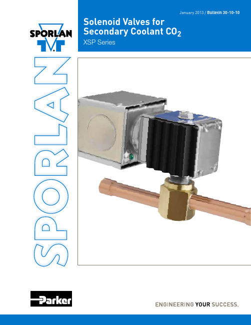
Solenoid Valves for Secondary Coolant CO2
XSP Series
⚠WARNING – USER RESPONSIBILITY
Failure or improper selection or improper use of the products described herein or related items can cause death, personal injury and property damage.
When ordering complete valves, specify Valve Type, Connections, Voltage and Cycles. When ordering Body Assembly, specify Valve Type and Connections. When ordering Coil Assembly ONLY, specify Coil Type, Voltage and Cycles. Example: MKC-1 120/50-60.
This document and other information from Parker Hannifin Corporation, its subsidiaries and authorized distributors provide product or system options for further investigation by users having technical expertise.
凯尔特尔自由寒冷储存设备说明书
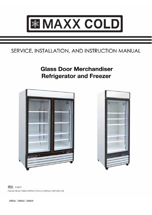
MXM1 / MXM2 / MXM3Service and Installation Manual2 RECEIVING & INSPECTING EQUIPMENT (2)SPECIFICA TIONS (3)INSTALLATION (4)OPERA TION (5)MAINTENANCE……………………………………………………………………….…………….7-9All rights reserved. Reproduction without written permission is prohibited.The serial number of all self-contained refrigerators and freezers is located inside the unit on the left hand side near the top on the wall.Always have the serial number of your unit available when calling for parts or service.Serial #:_____________________ ________________________ __________________________ This manual covers standard units only. If you have a custom unit, consult the customer service department at the number listed in the back cover.Even though most equipment is shipped crated, care should be taken during unloading so the equipment is not damaged while being moved into the building.1. Visually inspect the exterior of the package and skid or container. Any damage should be noted and reportedto the delivering carrier immediately.2. If damaged, open and inspect the contents with the carrier.3. In the event that the exterior is not damaged, yet upon opening, there is concealed damage to the equipmentnotify the carrier. Notification should be made verbally as well as in written form.4. Request an inspection by the shipping company of the damaged equipment. This should be done within 10days from receipt of the equipment.5. Be certain to check the compressor compartment housing and visually inspect the refrigeration package. Besure lines are secure and base is still intact.6. Freight carriers can supply the necessary damage forms upon request.7. Retain all crating material until an inspection has been made or waived.1 05/12 Initial release (A)2 03/17 Text Formats. Temperature Range.Service and Installation Manual3SWING GLASS DOOR REFRIGERATORSMODEL# V/Hz/Ph AMPS STORAGE CAPACITYCu-ft HP CHARGE OZ SHIP WEIGHT LBSNEMA PLUG MXM1-12R 115/60/1 6 12 3/8 12.0 254 5-15P MXM1-16R 115/60/1 6 16 3/8 12.0 282 5-15P MXM1-23R 115/60/1 6 23 3/8 12.0 331 5-15P MXM2-48R 115/60/1 7 48 1/2 18.7 540 5-15P MXM3-72R 115/60/1 10 72 3/421.2 741 5-15PSWING GLASS DOOR FREEZERSMODEL# V/Hz/Ph AMPS STORAGE CAPACITY Cu-ft HP CHARGE OZ SHIP WEIGHT LBS NEMAPLUGMXM1-12F 115/60/1 11 12 3/8 10.6 258 5-15P MXM1-16F 115/60/1 11 16 5/8 11.3 289 5-15P MXM1-23F 115/60/1 11 23 5/8 14.1 353 5-15P MXM2-48F 115/60/1 12 48 1 25.0 567 5-15P MXM3-72F115/60/11672 1-1/4 28.9 829 5-20PSLIDING GLASS DOOR REFRIGERATORMODEL# V/Hz/Ph AMPS STORAGE CAPACITYCu-ft HP CHARGE OZ SHIP WEIGHT LBSNEMA PLUG MXM2-48RS 115/60/1 7 481/218.7 540 5-15P· Read this entire manual to ensure proper usage.· Follow all safety precautions as described.· Keep this user manual for future reference. Visit for the most up to date version of this manual.· Disconnect the power cord before attempting to work on or clean equipment. Disconnect power if the appliance will be idle for a long period of time.· Do not attempt to remove any covers or parts yourself, as this can expose dangerous, high voltage wiring. Service should only be performed by an authorized or qualified technician. · Always route power cords away from areas where they can be walked on or damaged.· Never use extension cords, or plug more than one than one appliance into the same circuit. This can overload the power supply, which can result in electrical shock or fire.· Your appliance is equipped with a polarized, grounded power plug. Never attempt to remove the ground post or use a non-polarized adapter, without properly grounding the equipment.· If a replacement part is required at any point during the lifetime of this appliance, always insist on factory authorized components.Service and Installation Manual4 LocationUnits represented in this manual are intended for indoor use only . Be sure the location chosen has a floor strong enough to support the total weight of the cabinet and contents. A fully loaded unit can weigh as much as 1500 pounds. Reinforce the floor as necessary to provide for maximum loading. For the most efficient refrigeration, be sure to provide good air circulation inside and out.Inside cabinet:Do not pack the refrigerator so full that air cannot circulate. The refrigerated air is discharged at the top rear of the unit. It is important to allow for proper air flow from the top rear to the bottom of the unit. Obstructions to this air flow can cause evaporator coil freeze ups and loss of temperature or overflow of water from the evaporator drain pan. The shelves have a rear turn up on them to prevent this. However, bags and other items can still be located to the far rear of the cabinet. Air is brought into the evaporator coil with fans mounted to the front of thecoil. Prevent obstructions by locating large boxes and tall stacks of product to the bottom of the cabinet.Outside cabinet:Be sure that the unit has access to ample air. Avoid hot corners and locations near stoves and ovens. It is recommended that the unit be installed no closer than 6" from any wall with at least 12" of clear space above the unit. Should it become necessary to lay the unit on its side or back for any reason, allow at least 24 hours before start-up so as to allow compressor oil to flow back to the sump. Failure to meet this requirement can cause compressor failure and unit damage.LevelingA level cabinet looks better and will perform better because the doors will line up with the frames properly, the cabinet will not be subject to undue strain and the contents of the cabinet will not move around on the shelves. Use a level to make sure the unit is level from front to back and side to side. Because the unit is supplied with casters, no adjustments are available. Ensure the floor where the unit is to be located is level.Stabilizing Models are supplied on casters for your convenience, ease of cleaning underneath and for mobility. It is very important, however, that the cabinet be installed in a stable condition with the front wheels locked while in use.Standard warranties will be voided due to improper installation procedures.Electrical connectionRefer to the amperage data on page 3, the serial tag, your local code or the National Electrical Code to be sure the unit is connected to the proper power source. A protected circuit of the correct voltage and amperage must be run for connection of the line cord or a permanent connection to the unit.The ON/OFF switch must be turned to OFF and the unit disconnected from the power source whenever performing service, maintenance functions or cleaning the refrigerated area .Service and Installation Manual5Do not throw items into the storage area. Failure to follow theserecommendations could result in damage to the interior of the cabinet.Refrigeration cycleRefrigerators: Every 6 hours, the unit will shut off to allow the evaporator coil to defrost and the controller will display the defrost symbol. When the coil temperature reach 41ºF (5ºC) or after 20 minutes, the unit returns to the refrigeration cycle again. The suggested factory setting for temperature range is 34º to 40ºF (1ºC to 4ºC). Freezers: During the refrigeration cycle the controller supplies power to the condensing unit and evaporator fan motors. The evaporator fans will run at any time when the evaporator coil temperature is below 35ºF (2 ºC), and they will cycle off during defrost period. Every 6 hours, the unit will shut off and the defrost heater will defrost the evaporator coil and the controller will display the defrost symbol. When the coil temperature reach 45ºF (7 ºC) or after 20 minutes, the unit returns to the refrigeration cycle.1. Anti-Condensation heaters on the door frames work in conjunction with the compressor.2. The factory setting for temperature range is -7ºF to -3ºF (-22 ºC to -19 ºC).On/Off Switch:An on/off switch is located on the front of the bottom shroud. When the unit is on, the switch will glow green.Light Switch:A light switch is located next to on/off switch on the front of the bottom shroud.SOLID-STATE THERMOSTAT DESCRIPTIONSP ANEL1.1 KEY FUNCTIONT o display target set point; in programming mode it selects a parameter or confirms an operation T o start a manual defrostT o see the last temperature alarm; in programming mode it browses the parametercodes or increases the display valueT o see the last temperature alarm; in programming mode it browses the parametercodes or decreases the display valueKEY COMBINATIONTo lock & unlock the keyboardTo enter in programming modeT o return to the room temperature displayService and Installation Manual6 1.2 Function of LEDS2.1 HOW TO SEE THE SETPOINT1. Push and immediately release the SET key: the display will show the set point value.2. Push and immediately release the SET key or wait for 5 seconds to display the sensor value again. 2.2 HOW TO CHANGE THE SETPOINT1. Push the SET key for more than 2 seconds to change the set point value.2. The value of the set point will be displayed and the LED starts blinking.3. To change the set value push the or key within 10 seconds.4. To save the new set point value to memory, push the SET key again or wait 10 seconds. 2.3 HOW TO START A MANUAL DEFFROST Push the key for more than 2 seconds and a manual defrost will start. 2.4 HOW TO LOCK THE KEYBOARD 1. Press and hold both the and keys for more than 3 seconds.2. The “POF” message will be displayed and the keyboard will be locked. At this point, it will be possible only to see the set point or the MAX or Min temperature stored.3. If a key is pressed for more than 3 seconds the “POF” message will be displayed.2.5 HOW TO UNLOCK THE KEYBOARD Press and hold both the and keys together for more than 3 seconds, till the “Pon” message is displayed, then press either or key to select the item to view or program.HOW TO SEE THE ALARM AND RESET THE RECORDED ALARM 1. Push the or key, and the alarm signals will be displayed. 2. When the signal is displayed, hold the SET key until the “rst” message is displayed, and push the SET key again, the “rst” message will startblinking and the normal temperature will be displayed again.Service and Installation Manual7The power switch must be turned to OFF and the unit disconnected from the power source whenever performing service, maintenance functions or cleaning the refrigerated area.Refrigerators & FreezersThe interior and exterior can be cleaned using soap and warm water. If this isn't sufficient, try ammonia and water or a nonabrasive liquid cleaner. When cleaning the exterior, always rub with the "grain" of the stainless steel to avoid marring the finish.Do not use an abrasive cleaner because it will scratch the stainless steel and plastic and can damage the breaker strips and gaskets.Cleaning the Condenser CoilThe condenser coil requires regular cleaning, recommended is every 90 days. In some instances, you may find that there is a large amount of debris and dust or grease accumulated prior to the 90 day time frame. In these cases the condenser coil should be cleaned every 30 days.If the build up on the coil consists of only light dust and debris the condenser coil can be cleaned with a simple brush, heavier dust build up may require a vacuum or even compressed air to blow through the condenser coil.If heavy grease is present, there are de-greasing agents available for refrigeration use and specifically for the condenser coils. The condenser coil may require a spray with the de-greasing agent and then blown through with compressed air.Failure to maintain a clean condenser coil can initially cause high temperatures and excessive run times, continuous operation with dirty or clogged condenser coils can result in compressor failures. Neglecting the condenser coil cleaning procedures will void any warranties associated with the compressor or cost to replace the compressor.Never use a high pressure water wash for this cleaning procedure as water can damage the electrical components located near or at the condenser coil.In order to maintain proper refrigeration performance, the condenser fins must be cleaned of dust, dirt and grease regularly. It is recommended that this be done at least every three months. If conditions are such that the condenser is totally blocked in three months, the frequency of cleaning should be increased. Clean the condenser with a vacuum cleaner or stiff brush. If extremely dirty, a commercially available condenser cleaner may be required.Stainless Steel Care & CleaningT o prevent discoloration of rust on stainless steel several important steps need to be taken. First, we need to understand the properties of stainless steel. Stainless steel contains 70-80% iron which will rust. It alsocontains 12-30% chromium which forms an invisible passive film over the steels surface which acts as a shield against corrosion. As long as the protective layer is intact, the metal is still stainless. If the film is broken or contaminated, outside elements can begin to breakdown the steel and begin to form rust of discoloration.Service and Installation Manual8 Cleaning solutions need to be alkaline based or non-chloride cleaners. Any cleaner containing chlorides will damage the protective film of the stainless steel. Chlorides are also commonly found in hard water, salts, and household and industrial cleaners. If cleaners containing chlorides are used be sure to rinse repeatedly and dry thoroughly upon completion.Proper cleaning of stainless steel requires soft cloths or plastic scouring pads. NEVER USE STEEL PADS, WIRE BRUSHES OR SCRAPERS!Routine cleaning of stainless steel can be done with soap and water. Extreme stains or grease should be cleaned with a non-abrasive cleaner and plastic scrub pad. It is always good to rub withthe grain of the steel. There are also stainless steel cleaners available which can restore and preserve the finish of the steels protective layer.Early signs of stainless steel breakdown can consist of small pits and cracks. If this has begun, clean thoroughly and start to apply stainless steel cleaners in attempt to restore the passivity of the steel.Never use an acid based cleaning solution !Many food products have an acidic content which can deteriorate the finish. Be sure to clean the stainless steel surfaces of ALL food products. Common items include, tomatoes, peppers and other vegetables.Gasket MaintenanceGaskets require regular cleaning to prevent mold and mildew build up and also to keep the elasticity of the gasket. Gasket cleaning can be done with the use of warm soapy water. Avoid full strength cleaning products on gaskets as this can cause them to become brittle and prevent proper seals. Also, never use sharp tools or knives to scrape or clean the gasket which could possibly tear the gasket and rip the bellows.Gaskets can easily be replaced and don’t require the use of tools or authorized service persons. The gaskets are "Dart" style and can be pulled out of the groove in the door and new gaskets can be "pressed" back into place.Doors / HingesOver time and with heavy use doors the hinges may become loose. If it is noticed that the door isbeginning to sag, it may become necessary to tighten the screws that mount the hinge brackets to the frame of the unit. If the doors are loose or sagging this can cause the hinge to pull out of the frame which may damage both the doors and the door hinges. In some cases this can require qualified service agents or maintenance personnel.Drain MaintenanceEach unit has a drain located inside the unit which removes the condensation from the evaporator coil andevaporates it at an external condensate evaporator pan. Each drain can become loose or disconnected from moving or bumping the drain. If you notice excessive water accumulation on the inside of the unit, be sure the drain tube is connected from the evaporator housing to the condensate evaporator drain pan. If water iscollected underneath the unit you may want to check the condensate evaporator drain tube to be sure it is still located inside the drain pan. The leveling of the unit is important as the units are designed to drain properly when on a level surface, if your floor is not level this can also cause drain problems. Be sure all drain lines are free of obstructions typically food product is found blocking drain lines causing water to back up and overflow the drain pans.Service and Installation ManualSwing Door Replacement and Adjustment1. Open the bottom shroud and hold the door, then loosen the bottom hinge’s screws and take off the olddoor.2. Prepare the new door, insert top pin into the top hinge, get one bottom hinge to hold the door by thebottom pin, then fasten bottom hinge securely to the door frame with three screws.3. Allow the door to freely swing, make sure it swing closed by itself with no restriction.4. Plug the unit in and make sure the lock works.If not, adjust the door height by adding the plastic spacer/washer provided to the bottom hinge pin. Sliding Door Replacement and Adjustment1. Take off the hook from the counterweight of the door from the top of the door.2. Hold the door up until the bottom edge is over the bottom channel slightly, move the door out acrossthe channel, lay the door down.3. Prepare the new door, hold the door insert into top channel until bottom edge is over the bottom channel,move bottom of door across the channel wall and set it down to the channel.To Remove the Bottom Shroud1. Loosen and remove the top screws, slide the shroud up and out.Light Bulb ReplacementUpper light bulb replacement:1. Loosen the screws in the bottom of the top shroud, swing the top shroud up until it is held by the top ofthe cabinet, now light bulb can be replaced.LED light bulb replacement:1. Take the cover off, then the LED bulb can be replaced.9Service and Installation Manual 10。
1002 212 025说明书

Safety Information . . . . . . . . . . . . . . . . . . . . . . . . . . . . . . . . . . 2 Warranty . . . . . . . . . . . . . . . . . . . . . . . . . . . . . . . . . . . . . . . . . . 3 Pre-Installation . . . . . . . . . . . . . . . . . . . . . . . . . . . . . . . . . . . . . 3 Installation . . . . . . . . . . . . . . . . . . . . . . . . . . . . . . . . . . . . . . . . 6Before you begin, carefully read and understand the instructions in this manual. Please follow the instructions in the order presented inthis manual and observe all warnings and cautions.This mount has been tested to support a television with a minimum of 20 in. (51 cm) and a maximum 56 in. (142 cm)diagonal screen and a weight up to 80 lbs. (36 kgs).The manufacturer warrants that it will replace or repair this item, free of charge, at the manufacturer’s sole discretion, should it prove defective in materials or workmanship.This warranty does not apply to:□Normal wear and tear□Friction damage□Coating defects□Defects caused by loosened screws, nuts, or bolts□Improperly mounting the bracket to the wall□Improperly installing the bracket to the display□Failure to properly follow installation instructions□Modifi cation or repairs not made or authorized by the manufacturer□Loading beyond permitted load□Intentional misuseContact the Customer Service Team at 1-877-527-0313 or visit .PLANNING INSTALLATIONCompare all parts in the package with the Hardware Included and Package Contents lists in this manual. If any part is missing or damaged, do not install this wall mount system and call customer service at 1-877-527-0313 or visit .This wall mount bracket is compatible with VESA 100/200/300/400 mm mounting holes.PLANNING WALL PLACEMENTWhen selecting a wall to mount your display, keep the following in mind:□Select a place with easy access to power outlets, cable input sources, and connections for speakers and accessories.□Avoid direct sunlight, heat, and vibrations and do not place in direct fl ow of traffi c.□Select a weight-bearing wall. The wall must be able to safely support four times the combined load of the equipment and all attached hardware and components.PLANNING MOUNTING HEIGHTThe optimal viewing height is to center the display at eye level when seated. Many people consider this to be too low for a wall mount, and commonly use the following rule for placement:□Position the bottom of the display no higher than eye level when seated, and the top of the display no higher than eye level when standing. Anything within these limits should normally provide a comfortable viewing experience.ENSURING WALL STABILITYCarefully inspect the wall area you have selected. Examine the wall surface before you begin drilling.□For concrete walls, check for damaged or loose concrete and do not drill in those areas. □For brick wall, never drill into the mortar between blocks.□For wood studs, locate the wall studs and drill in the center of the stud.TOOLS REQUIRED (NOT INCLUDED IN THE PACKAGING)Power drill5-32 in. (4 mm) wood drill bit or 3/8 in. (10 mm) masonry drillbitsPhillipsscrewdriverStud finderMeasuringtapePencil HammerHARDWARE INCLUDEDAA BB CC DD EEJJFF GG HH IIPACKAGE CONTENTS7 Attaching the mounting arm to the□Align the mounting arm holes with the pre-drilled holes in the wall.□Use the level (C) to ensure that the mounting arm (A) is level on the wall.□Attach the mounting arm (A) to the wall using lag bolts(BB). Tighten the bolts (BB) securely using a Phillipsscrewdriver and a socket tool (not included).8Attaching the mounting plate to theTV (VESA 100 and 200)This procedure describes how to attach the mounting plate to VESA 100 and 200 TVs. For VESA 300 and 400, proceed to step 9. □If necessary, align spacers (EE) or (FF) over the mounting holes on the back of your TV. □Position the wall plate (A) over the TV and attach using the appropriately sized bolts (CC or DD) and washers(GG or HH).EE/FFAGG/HHDD AGG/HH100x100 / 200x200100x100 / 200x200CC9Attaching the mounting plate to the TV (VESA 300 and 400)□Attach the left and right arm extenders (B1 and B2) to the wall plate (A) using M6 x 8 bolts (II). □Align spacers (EE or FF) over the mounting holes on the back of your TV. □Position the wall plate (A) with extenders (B) over spacers (EE or FF) and attach them to the TV using the appropriate sized bolts (CC or DD) and washers (GG or HH).CC II JJB1B2B1B2GG/HHDD EE/FFGG/HH12 Adjusting the angle of the TV□Adjust the angle of the TV by loosening the handle (1) on the wall plate assembly (A). Refer to the fi gure for the various angle adjustments. Securely tighten the handle (1) when you are fi nished.Questions, problems, missing parts? Before returning to the store, call Commercial Electric Customer Service8 a.m. - 7 p.m., EST, Monday-Friday, 9 a.m. - 6 p.m., EST, Saturday1-877-527-0313Retain this manual for future use.。
ELX1227技术数据参考手册说明书

NRSEEpoxy sealed radial lead NTC thermistorProduct features• Epoxy sealed radial NTC thermistor • Temperature sensing, quick response time • 1.4 millimeter size• Wide resistance range:1 k Ω to 470 k Ω•Non-linear change in resistance vs temperaturePb HALOGENHFFREEPackaging information•Bulk: 500 parts per poly bagT able 1. Part numberingNRS E xxy a xxxx Bx b zFamily nameNRSPackaging typeE = epoxy coatedResistancexxy= x.x * 10y Ωex: 103 = 1.0 * 102 = 1000 ΩResistance tolerance codeF = ±1%, H = ±3%Beta tolerance codeF = ±1%,G = ±2%,H = ±3%Beta type codeB1 = 25/50, B2 = 25/85Beta value ex: 3465, 4215, etcLead styleDifferent leaddimensionsApplications• Industrial Process Control • Commercial appliances•Battery, supercapacitor and energy storage systems• Uninterruptible power supplies • Consumer appliances •Medical devices•Heating, ventilation and air conditioning, Refrigeration (HVACR)• Food service equipment • IoT• White goods/household appliances •Computer and peripheral productsEnvironmental compliance and general specificationsSee electrical specification table for option details2Technical Data ELX1227Effective July 2022NRSEEpoxy sealed radial lead NTC thermistor/electronicsMechanical parameters- mm1. Enameled CCS leads with terminals tinned2. Epoxy head3Technical Data ELX1227Effective July 2022NRSEEpoxy sealed radial lead NTC thermistor /electronics Electrical specificationsPart numberZero power resistance @ 25°C R 25 (kΩ)R 25Tolerance (Part number code)Beta type (Part number code)Beta value (K)Betatolerance (Part number code)Maximum power @ +25°C P max (mW)Dissipationfactor (mW/°C)Thermal time constant T (second)Operation temperature TL~TU(°C)NRSE103axxxxBxb 1±1% (F), ±3% (H)25/85 (B2)3435±2% (G), ±3% (H)50≥ 4≤ 7-30 to +105NRSE683axxxxBxb 6.8±1% (F), ±3% (H)25/85 (B2)3470±2% (G), ±3% (H)50≥ 4≤ 7-30 to +105NRSE683axxxxBxb 6.8±1% (F), ±3% (H)25/85 (B2)3975±2% (G), ±3% (H)50≥ 4≤ 7-30 to +105NRSE104axxxxBxb 10±1% (F), ±3% (H)25/85 (B2)3435±1% (F), ±3% (H)50≥ 4≤ 7-30 to +105NRSE104axxxxBxb 10±1% (F), ±3% (H)25/85 (B2)3975±1% (F), ±3% (H)50≥ 4≤ 7-30 to +105NRSE203axxxxBxb 2±1% (F), ±3% (H)25/85 (B2)3435±1% (F), ±3% (H)50≥ 4≤ 7-30 to +105NRSE224axxxxBxb 22±1% (F), ±3% (H)25/85 (B2)3740±1% (F), ±3% (H)50≥ 4≤ 7-30 to +105NRSE334axxxxBxb 33±1% (F), ±3% (H)25/85 (B2)3975±1% (F), ±3% (H)50≥ 4≤ 7-30 to +105NRSE474axxxxBxb 47±1% (F), ±3% (H)25/85 (B2)4090±1% (F), ±3% (H)50≥ 4≤ 7-30 to +105NRSE504axxxxBxb 50±1% (F), ±3% (H)25/85 (B2)3950±1% (F), ±3% (H)50≥ 4≤ 7-30 to +105NRSE504axxxxBxb 50±1% (F), ±3% (H)25/85 (B2)4050±1% (F), ±3% (H)50≥ 4≤ 7-30 to +105NRSE105axxxxBxb 100±1% (F), ±3% (H)25/85 (B2)4000±1% (F), ±3% (H)50≥ 4≤ 7-30 to +105NRSE105axxxxBxb 100±1% (F), ±3% (H)25/85 (B2)4190±2% (G), ±3% (H)50≥ 4≤ 7-30 to +105NRSE105axxxxBxb 100±1% (F), ±3% (H)25/85 (B2)4360±2% (G), ±3% (H)50≥ 4≤ 7-30 to +105NRSE475axxxxBxb 470±1% (F), ±3% (H)25/85 (B2)4570±2% (G), ±3% (H)50≥ 4≤ 7-30 to +105NRSE203axxxxBxb 2±1% (F), ±3% (H)25/50 (B1)3380±2% (G), ±3% (H)50≥ 4≤ 7-30 to +105NRSE503axxxxBxb 5±1% (F), ±3% (H)25/50 (B1)3420±2% (G), ±3% (H)50≥ 4≤ 7-30 to +105NRSE503axxxxBxb 5±1% (F), ±3% (H)25/50 (B1)3900±2% (G), ±3% (H)50≥ 4≤ 7-30 to +105NRSE104axxxxBxb 10±1% (F), ±3% (H)25/50 (B1)3380±1% (F), ±3% (H)50≥ 4≤ 7-30 to +105NRSE104axxxxBxb 10±1% (F), ±3% (H)25/50 (B1)4000±1% (F), ±3% (H)50≥ 4≤ 7-30 to +105NRSE104axxxxBxb 10±1% (F), ±3% (H)25/50 (B1)3950±1% (F), ±3% (H)50≥ 4≤ 7-30 to +105NRSE684axxxxBxb 68±1% (F), ±3% (H)25/50 (B1)3950±1% (F), ±3% (H)50≥ 4≤ 7-30 to +105NRSE224axxxxBxb 22±1% (F), ±3% (H)25/50 (B1)3700±1% (F), ±3% (H)50≥ 4≤ 7-30 to +105NRSE474axxxxBxb 47±1% (F), ±3% (H)25/50 (B1)3950±1% (F), ±3% (H)50≥ 4≤ 7-30 to +105NRSE474axxxxBxb 47±1% (F), ±3% (H)25/50 (B1)4020±1% (F), ±3% (H)50≥ 4≤ 7-30 to +105NRSE105axxxxBxb 100±1% (F), ±3% (H)25/50 (B1)3950±1% (F), ±3% (H)50≥ 4≤ 7-30 to +105NRSE105axxxxBxb 100±1% (F), ±3% (H)25/50 (B1)4120±2% (G), ±3% (H)50≥ 4≤ 7-30 to +105NRSE225axxxxBxb220±1% (F), ±3% (H)25/50 (B1)4370±2% (G), ±3% (H)50≥ 4≤ 7-30 to +105a= Enter resistance tolerance code from table above (F = ±1%, H = ±3%)Bx= Enter Beta code from table above (B1 = 25/50, B2 = 25/85)b= Enter Beta tolerance code from table above (F = ±1%, G = ±2%, H = ±3%)4Technical Data ELX1227Effective July 2022NRSEEpoxy sealed radial lead NTC thermistor/electronicsPart number NRSE1033435NRSE6833470NRSE6833975NRSE2033435NRSE1043435NRSE1043975NRSE2243740NRSE3343975NRSE4744090NRSE5043950B typeB25/85B25/85B25/85B25/85B25/85B25/85B25/85B25/85B25/85B25/85Temperature (°C)Resistance (kΩ)Resistance (kΩ)Resistance (kΩ)Resistance (kΩ)Resistance (kΩ)Resistance (kΩ)Resistance (kΩ)Resistance (kΩ)Resistance (kΩ)Resistance(kΩ)-4020.0887.5162.59532539.55751116.4217001625-3919.1483.93153.9691.71304.8337.47541.351045.231590.291522.75-3818.2480.51145.8988.53286.0135.55509.86978.991488.281427.54-3717.3877.24138.2785.46268.4533.74480.37917.341393.41338.83-3616.5674.11131.0682.51252.0632.03452.75859.931305.091256.14-3515.7871.1124.2579.66236.7630.41426.86806.461222.881179.05-3415.0468.23117.8176.9222.4728.88402.6756.621146.311107.13-3314.3365.47111.7274.25209.1127.43379.85710.151074.971040.02-3213.6662.83105.9671.69196.6326.05358.5666.811008.47977.36-3113.0160.3100.5269.22184.9524.76338.48626.37946.45918.84-3012.457.8895.3766.84174.0323.53319.68588.62888.6864.16-2911.8255.5690.4964.54163.8222.36302.02553.36834.61813.06-2811.2653.3385.8862.32154.2521.26285.44520.42784.21765.27-2710.7351.281.5260.18145.320.22269.86489.64737.13720.56-2610.2349.1677.3958.11136.9119.23255.21460.85693.14678.73-259.7547.273.4856.12129.0518.3241.44433.93652.02639.56-249.2945.3269.7754.19121.6817.41228.49408.73613.57602.88-238.8543.5266.2752.34114.7816.57216.3385.14577.61568.52-228.4441.7962.9550.54108.315.77204.83363.06543.96536.31-218.0440.1459.8148.81102.2215.02194.03342.36512.45506.11-207.6738.5556.8347.1496.5114.3183.86322.97482.95477.78-197.3137.0354.0145.5391.1513.62174.28304.79455.3451.21-18 6.9635.5751.3443.9786.1212.98165.24287.74429.4426.26-17 6.6434.1748.8142.4781.412.37156.73271.74405.11402.83-16 6.3332.8346.4141.0276.9511.79148.7256.72382.34380.83-15 6.0331.5444.1339.6272.7811.24141.13242.62360.97360.15-14 5.7530.3141.9738.2768.8510.72133.98229.37340.91340.72-13 5.4929.1239.9336.9665.1610.22127.23216.93322.08322.44-12 5.2327.9937.9935.761.689.75120.86205.23304.4305.25-11 4.9926.936.1534.4958.419.31114.85194.23287.79289.08-10 4.7625.8534.4133.3155.338.88109.16183.88272.17273.85-9 4.5424.8532.7532.1852.428.48103.79174.15257.49259.51-8 4.3323.8931.1831.0849.698.198.71164.98243.68246-7 4.1322.9629.6930.0347.117.7393.91156.35230.69233.28-6 3.9422.0828.282944.687.3989.37148.22218.46221.28-5 3.7621.2326.9428.0242.397.0685.07140.56206.95209.97-4 3.5920.4125.6627.0740.23 6.7481133.34196.11199.3-3 3.4219.6324.4526.1538.19 6.4577.15126.54185.9189.23-2 3.2718.8823.325.2636.27 6.1673.5120.12176.28179.73-1 3.1218.1522.2124.434.45 5.8970.05114.06167.21170.760 2.9817.4621.1823.5732.73 5.6466.78108.34158.65162.291 2.8516.820.1922.7731.11 5.3963.67102.94150.58154.292 2.7216.1619.262229.58 5.1660.7397.84142.96146.723 2.615.5518.3721.2628.13 4.9457.9493.02135.78139.574 2.4814.9617.5220.5426.76 4.7355.2988.47128.99132.815 2.3714.3916.7219.8425.46 4.5352.7884.17122.58126.416 2.2713.8515.9619.1724.23 4.3450.480.1116.52120.367 2.1713.3315.2318.5223.07 4.1648.1476.25110.8114.638 2.0712.8314.5417.8921.97 3.9845.9972.6105.39109.219 1.9812.3513.8917.2920.93 3.8243.9469.15100.27104.0710 1.8911.8913.2616.7119.95 3.664265.8995.4399.211 1.8111.4512.6716.1419.01 3.5140.1662.890.8594.5912 1.7311.0212.115.618.13 3.3738.4159.8786.5190.2213 1.6610.6211.5615.0717.29 3.2336.7457.0982.4186.0714 1.5910.2211.0514.5616.49 3.135.1654.4678.5282.1415 1.529.8510.5714.0715.74 2.9833.6551.9674.8478.4116 1.469.4810.113.615.02 2.8632.2149.5971.3574.8717 1.49.149.6613.1414.34 2.7430.8547.3568.0471.51181.348.89.2412.713.7 2.6429.5445.2164.968.32T emperature characteristics5Technical Data ELX1227Effective July 2022NRSEEpoxy sealed radial lead NTC thermistor /electronics T emperature characteristics, cont.Part number NRSE1033435NRSE6833470NRSE6833975NRSE2033435NRSE1043435NRSE1043975NRSE2243740NRSE3343975NRSE4744090NRSE5043950B typeB25/85B25/85B25/85B25/85B25/85B25/85B25/85B25/85B25/85B25/85Temperature (°C)Resistance (kΩ)Resistance (kΩ)Resistance (kΩ)Resistance (kΩ)Resistance (kΩ)Resistance (kΩ)Resistance (kΩ)Resistance (kΩ)Resistance (kΩ)Resistance(kΩ)191.288.488.8412.2713.09 2.5328.343.1961.9365.2920 1.238.178.4611.8612.5 2.4327.1241.2759.1162.4121 1.187.888.0911.4611.95 2.342639.4456.4359.6722 1.137.597.7511.0811.43 2.2524.9337.7153.8957.0723 1.097.327.4210.710.93 2.1623.936.0651.4754.5924 1.047.057.110.3510.45 2.0822.9334.4949.1852.24251 6.8 6.81010222334750260.9603 6.56 6.519.679.57 1.9221.1131.5844.9347.87270.9224 6.32 6.249.349.16 1.8520.2730.2342.9645.84280.88626.1 5.989.038.77 1.7819.4628.9541.0943.91290.8517 5.88 5.738.738.4 1.7218.6927.7339.3142.07300.8188 5.67 5.498.448.05 1.6517.9526.5637.6240.32310.7873 5.47 5.278.167.71 1.5917.2525.4536.0138.65320.7573 5.28 5.057.897.39 1.5416.5724.434.4837.06330.7287 5.1 4.857.627.09 1.4815.9323.3933.0235.54340.7013 4.92 4.657.37 6.8 1.4315.3222.4331.6334.09350.6752 4.75 4.467.13 6.52 1.3814.7321.5230.332.71360.6502 4.58 4.28 6.89 6.25 1.3314.1720.6429.0431.4370.6263 4.43 4.11 6.666 1.2813.6319.8127.8430.14380.6035 4.27 3.95 6.44 5.76 1.2313.1219.0226.6928.94390.5817 4.13 3.79 6.23 5.53 1.1912.6318.2625.627.8400.5608 3.99 3.64 6.03 5.31 1.1512.1517.5424.5626.7410.5409 3.85 3.5 5.83 5.1 1.1111.716.8423.5625.66420.5218 3.72 3.36 5.64 4.9 1.0711.2716.1822.6224.66430.5036 3.59 3.23 5.45 4.71 1.0410.8615.5521.7123.7440.4861 3.47 3.1 5.27 4.53110.4614.9520.8522.79450.4693 3.36 2.98 5.1 4.350.966810.0814.3720.0221.92460.4533 3.24 2.87 4.94 4.190.93459.7213.8219.2321.09470.438 3.14 2.76 4.78 4.030.90349.3713.318.4820.29480.4233 3.03 2.66 4.62 3.870.87369.0412.7917.7619.52490.4092 2.93 2.56 4.47 3.730.84498.7212.3117.0718.79500.3957 2.84 2.46 4.33 3.590.81738.4111.8516.4218.09510.3827 2.74 2.37 4.19 3.450.79088.1111.4115.7917.43520.3703 2.65 2.28 4.05 3.330.76537.8310.9915.1916.78530.3584 2.57 2.2 3.92 3.20.74087.5610.5814.6116.17540.347 2.48 2.11 3.8 3.090.71737.310.1914.0615.58550.336 2.4 2.04 3.67 2.970.69467.059.8213.5315.02560.3255 2.33 1.96 3.56 2.870.6728 6.819.4713.0314.48570.3154 2.25 1.89 3.44 2.760.6518 6.589.1312.5513.96580.3057 2.18 1.82 3.34 2.660.6315 6.358.812.0813.46590.2963 2.11 1.76 3.23 2.570.6121 6.148.4911.6412.98600.2874 2.05 1.7 3.13 2.480.5933 5.948.1911.2212.53610.2788 1.98 1.64 3.03 2.390.5753 5.747.910.8112.09620.2705 1.92 1.58 2.93 2.310.5579 5.557.6210.4211.67630.2625 1.86 1.52 2.84 2.230.5411 5.377.3610.0511.26640.2549 1.8 1.47 2.75 2.150.525 5.197.19.6910.88650.2475 1.75 1.42 2.67 2.080.5094 5.02 6.869.3410.5660.2404 1.69 1.37 2.5920.4944 4.86 6.629.0110.14670.2336 1.64 1.32 2.51 1.940.4799 4.7 6.48.79.8680.227 1.59 1.28 2.43 1.870.4659 4.55 6.188.399.47690.2207 1.55 1.23 2.35 1.810.4525 4.41 5.978.19.15700.2146 1.5 1.19 2.28 1.750.4395 4.27 5.777.828.85710.2087 1.45 1.15 2.21 1.690.4269 4.13 5.587.558.55720.203 1.41 1.11 2.14 1.630.4148 4.01 5.397.38.27730.1976 1.37 1.08 2.08 1.580.4031 3.88 5.217.058740.1923 1.33 1.04 2.02 1.530.3919 3.76 5.04 6.817.74750.1872 1.29 1.01 1.96 1.480.381 3.64 4.88 6.587.49760.1823 1.250.974 1.9 1.430.3704 3.53 4.72 6.367.24770.1776 1.220.9424 1.84 1.380.3603 3.43 4.57 6.157.016Technical Data ELX1227Effective July 2022NRSEEpoxy sealed radial lead NTC thermistor/electronicsT emperature characteristics, cont.Part number NRSE1033435NRSE6833470NRSE6833975NRSE2033435NRSE1043435NRSE1043975NRSE2243740NRSE3343975NRSE4744090NRSE5043950B typeB25/85B25/85B25/85B25/85B25/85B25/85B25/85B25/85B25/85B25/85Temperature (°C)Resistance (kΩ)Resistance (kΩ)Resistance (kΩ)Resistance (kΩ)Resistance (kΩ)Resistance (kΩ)Resistance (kΩ)Resistance (kΩ)Resistance (kΩ)Resistance(kΩ)780.1730 1.180.9120 1.79 1.340.3504 3.32 4.42 5.95 6.79790.1686 1.150.8827 1.73 1.300.3409 3.22 4.28 5.75 6.57800.1643 1.120.8545 1.68 1.260.3318 3.12 4.14 5.56 6.36810.1602 1.080.8274 1.63 1.220.3229 3.03 4.01 5.38 6.16820.1562 1.050.8013 1.59 1.180.3143 2.94 3.89 5.21 5.97830.1524 1.020.7761 1.54 1.140.3060 2.85 3.77 5.04 5.79840.14870.99520.7519 1.49 1.110.2980 2.77 3.65 4.88 5.61850.14510.96760.7286 1.45 1.070.2902 2.69 3.54 4.72 5.43860.14160.94100.7061 1.41 1.040.2827 2.61 3.43 4.57 5.27870.13830.91520.6845 1.37 1.010.2754 2.54 3.32 4.43 5.11880.13500.89030.6636 1.330.97640.2684 2.46 3.22 4.29 4.95890.13190.86610.6435 1.290.94700.2615 2.39 3.12 4.15 4.80900.12880.84280.6241 1.260.91850.2549 2.32 3.03 4.02 4.66910.12590.82030.6054 1.220.89110.2486 2.26 2.94 3.90 4.52920.12300.79840.5874 1.190.86470.2424 2.20 2.85 3.78 4.38930.12020.77730.5700 1.150.83910.2364 2.13 2.77 3.66 4.25940.11760.75680.5532 1.120.81450.2305 2.07 2.68 3.55 4.13950.11500.73700.5370 1.090.79070.2249 2.02 2.61 3.45 4.01960.11240.71790.5214 1.060.76780.2194 1.96 2.53 3.34 3.89970.11000.69930.5063 1.030.74560.2141 1.91 2.46 3.24 3.78980.10760.68130.4918 1.000.72420.2090 1.86 2.39 3.14 3.67990.10530.66390.47770.97750.70350.2040 1.81 2.32 3.05 3.571000.10310.64700.46410.95130.68350.1992 1.76 2.25 2.96 3.461010.10090.63070.45100.92600.66410.1945 1.71 2.19 2.87 3.371020.09880.61490.43840.90140.64550.1900 1.66 2.12 2.79 3.271030.09680.59950.42610.87770.62740.1856 1.62 2.07 2.71 3.181040.09480.58460.41430.85470.61000.1813 1.58 2.01 2.63 3.091050.09290.57020.40290.83240.59310.1771 1.54 1.95 2.56 3.007Technical Data ELX1227Effective July 2022NRSEEpoxy sealed radial lead NTC thermistor /electronics T emperature characteristicsPart number NRSE5044050NRSE1054000NRSE1054190NRSE1054360NRSE4754570NRSE2033380NRSE5033420NRSE5033900NRSE1043380NRSE1044000B typeB25/85B25/85B25/85B25/85B25/85B25/50B25/50B25/50B25/50B25/50Temperature (°C)Resistance (kΩ)Resistance (kΩ)Resistance (kΩ)Resistance (kΩ)Resistance (kΩ)Resistance (kΩ)Resistance (kΩ)Resistance (kΩ)Resistance (kΩ)Resistance(kΩ)-4016253100330036002500039.890160195325-391524.572910.563098.573377.1923222.2937.6985.53150.08184.63305.06-381430.872733.692910.373169.1421580.9535.7181.3140.82174.87286.45-371343.412568.52734.472974.7920064.7933.8477.3132.19165.67269.05-361261.752414.172570.022793.1918663.6232.0773.5124.13157.01252.8-351185.482269.932416.232623.4717368.1230.4169.91116.6148.84237.61-341114.212135.072272.352464.7816169.7728.8466.5109.57141.14223.4-331047.592008.932137.72316.3715060.7727.3663.28103133.89210.11-32985.31890.92011.652177.5414034.0125.9660.2296.86127.04197.67-31927.031780.431893.632047.6313082.9524.6457.3291.12120.58186.03-30872.5216771783.071926.0212201.6323.3954.5885.75114.48175.13-29821.481580.121679.481812.1611384.5722.2151.9780.72108.73164.93-28773.71489.351582.391705.5110626.7421.149.576.02103.29155.36-27728.951404.261491.361605.619923.5620.0547.1671.6198.15146.4-26687.011324.491405.991511.989270.819.0544.9367.4993.3138-25647.71249.661325.91424.228664.5818.1142.8263.6288.71130.12-24610.851179.461250.741341.938101.3517.2240.826084.38122.73-23576.281113.571180.21264.747577.8416.3838.9256.680.28115.8-22543.841051.71113.951192.337091.0415.5837.1153.4176.39109.29-21513.4993.61051.741124.386638.1914.8335.450.4272.72103.18-20484.82939.01993.291060.596216.7514.1133.7747.6169.2597.44-19457.98887.7938.351000.75824.3813.4432.2244.9865.9692.04-18432.77839.47886.71944.445458.9312.830.7542.562.8486.98-17409.07794.11838.15891.65118.4212.1929.3640.1859.8882.21-16386.79751.44792.48841.93480111.6228.0337.9957.0977.74-15365.84711.28749.5795.254505.0111.0726.7735.9354.4373.52-14346.14673.48709.06751.364228.8910.5625.573451.9269.56-13327.59637.88670.98710.083971.1910.0724.4232.1849.5365.83-12310.14604.36635.13671.253730.69.623.3430.4747.2762.32-11293.7572.77601.36634.73505.919.1622.3128.8645.1259.01-10278.23542.99569.54600.313295.968.7421.3227.3443.0855.9-9263.64514.92539.56567.933099.738.3520.3925.9241.1552.96-8249.9488.45511.29537.442916.257.9719.524.5739.3150.2-7236.94463.47484.63508.712744.637.6118.6523.337.5647.59-6224.73439.9459.49481.652584.037.2717.8422.135.945.13-5213.2417.65435.77456.142433.7 6.9517.0720.9834.3342.81-4202.33396.65413.38432.12292.93 6.6416.3419.9132.8340.62-3192.07376.81392.25409.422161.07 6.3515.6418.9131.438.56-2182.38358.06372.29388.042037.5 6.0714.9817.9630.0536.61-1173.23340.35353.45367.871921.66 5.8114.3417.0628.7634.770164.58323.6335.65348.831813.03 5.5613.7416.2227.5333.031156.41307.76318.82330.861711.12 5.3213.1615.4226.3631.382148.69292.78302.92313.91615.49 5.0912.6114.6625.2529.833141.39278.61287.88297.881525.72 4.8812.0913.9524.1928.364134.49265.2273.67282.741441.42 4.6711.5913.2723.1826.975127.96252.5260.22268.451362.23 4.4811.1112.6322.2225.666121.78240.48247.49254.931287.81 4.2910.6612.0321.324.427115.93229.09235.44242.161217.86 4.1110.2211.4620.4323.248110.39218.3224.04230.091152.08 3.949.8110.9119.5922.139105.14208.07213.25218.661090.2 3.789.4110.418.821.0710100.17198.37203.02207.861031.98 3.639.039.9118.0420.071195.47189.18193.33197.64977.17 3.488.679.4517.3219.131291180.46184.15187.96925.57 3.348.339.0216.6318.231386.77172.19175.45178.81876.96 3.2188.615.9717.381482.76164.33167.2170.13831.17 3.087.688.2115.3416.571578.95156.88159.38161.92788.01 2.967.387.8414.7315.811675.34149.81151.96154.14747.32 2.847.097.4814.1615.081771.91143.08144.92146.77708.95 2.73 6.827.1513.6114.41868.66136.7138.24139.78672.75 2.62 6.55 6.8313.0913.748Technical Data ELX1227Effective July 2022NRSEEpoxy sealed radial lead NTC thermistor/electronicsT emperature characteristics, cont.Part number NRSE5044050NRSE1054000NRSE1054190NRSE1054360NRSE4754570NRSE2033380NRSE5033420NRSE5033900NRSE1043380NRSE1044000B typeB25/85B25/85B25/85B25/85B25/85B25/50B25/50B25/50B25/50B25/50Temperature (°C)Resistance (kΩ)Resistance (kΩ)Resistance (kΩ)Resistance (kΩ)Resistance (kΩ)Resistance (kΩ)Resistance (kΩ)Resistance (kΩ)Resistance (kΩ)Resistance(kΩ)1965.57130.63131.9133.16638.59 2.52 6.3 6.5312.5813.122062.63124.87125.87126.88606.34 2.42 6.06 6.2412.112.532159.84119.38120.16120.93575.89 2.33 5.83 5.9711.6511.972257.19114.17114.73115.28547.13 2.24 5.61 5.7111.2111.442354.67109.21109.57109.92519.96 2.16 5.4 5.4610.7910.942452.28104.49104.66104.83494.28 2.08 5.19 5.2210.3810.46255010010010047025510102647.8395.7395.5795.41447.04 1.93 4.81 4.799.639.572745.7791.6691.3591.06425.33 1.85 4.64 4.589.289.152843.8187.7887.3486.92404.78 1.79 4.47 4.398.948.762941.9484.0983.5382.99385.33 1.72 4.3 4.218.628.393040.1680.5779.979.26366.92 1.66 4.15 4.038.318.033138.4777.2176.4575.71349.48 1.64 3.878.017.693236.8574.0273.1672.34332.96 1.54 3.85 3.717.727.373335.3170.9770.0269.13317.31 1.49 3.71 3.567.457.063433.8568.0667.0466.07302.47 1.44 3.58 3.417.19 6.773532.4565.2964.263.17288.41 1.39 3.46 3.27 6.94 6.493631.1262.6461.4960.41275.07 1.34 3.33 3.14 6.69 6.223729.8560.1258.9157.78262.42 1.29 3.22 3.02 6.46 5.973828.6357.7156.4555.27250.42 1.25 3.1 2.9 6.24 5.723927.4755.4154.152.89239.02 1.23 2.78 6.03 5.494026.3753.2151.8650.62228.2 1.16 2.89 2.68 5.82 5.274125.3251.1149.7348.46217.93 1.12 2.79 2.57 5.62 5.064224.3149.147.6946.4208.18 1.09 2.7 2.47 5.43 4.864323.3547.1845.7544.43198.91 1.05 2.61 2.38 5.25 4.674422.4345.3543.8942.56190.1 1.01 2.52 2.29 5.08 4.484521.5543.642.1240.78181.720.9809 2.43 2.2 4.91 4.314620.7141.9240.4339.08173.760.9487 2.35 2.12 4.75 4.144719.9140.3238.8137.45166.190.9178 2.28 2.04 4.59 3.984819.1438.7837.2735.91158.980.8881 2.2 1.96 4.44 3.834918.4137.3235.7934.43152.130.8595 2.13 1.89 4.3 3.685017.7135.9134.3833.02145.60.832 2.06 1.82 4.16 3.545117.0334.5733.0431.68139.390.8056 1.99 1.75 4.03 3.415216.3933.2831.7530.39133.470.7801 1.93 1.69 3.9 3.285315.7832.0530.5229.16127.840.7556 1.87 1.63 3.78 3.165415.1930.8629.3427.99122.470.7321 1.81 1.57 3.66 3.045514.6229.7328.2126.87117.350.7094 1.75 1.51 3.54 2.935614.0828.6527.1325.81112.480.6875 1.69 1.46 3.43 2.825713.5727.6126.124.78107.830.6665 1.64 1.41 3.33 2.725813.0726.6125.1123.81103.40.6462 1.59 1.36 3.22 2.625912.625.6524.1722.8799.170.6266 1.54 1.31 3.12 2.526012.1424.7423.2621.9895.130.6078 1.49 1.26 3.03 2.436111.723.8622.3921.1391.280.5896 1.45 1.22 2.94 2.356211.2823.0121.5620.3187.610.5721 1.4 1.18 2.85 2.266310.8822.220.7619.5384.10.5553 1.36 1.14 2.76 2.186410.521.432018.7880.750.539 1.32 1.1 2.68 2.116510.1320.6819.2718.0677.540.5233 1.28 1.06 2.6 2.03669.7719.9618.5717.3874.490.5081 1.24 1.03 2.52 1.96679.4319.2817.916.7271.560.4935 1.20.9909 2.45 1.89689.118.6117.2516.168.770.4794 1.170.9579 2.38 1.83698.7917.9816.6315.4966.10.4658 1.130.9262 2.31 1.77708.4917.3716.0414.9263.550.4526 1.10.8958 2.24 1.71718.216.7815.4714.3661.110.4399 1.070.8665 2.18 1.65727.9216.2214.9213.8458.770.4277 1.040.8384 2.12 1.59737.6515.6814.413.3356.530.4158 1.010.8113 2.06 1.54747.415.1613.8912.8454.390.40440.97890.78522 1.49757.1514.6513.4112.3752.350.39330.95110.7601 1.94 1.4476 6.9114.1712.9411.9350.390.38260.92430.736 1.89 1.3977 6.6813.7112.511.548.510.37220.89830.7128 1.84 1.359Technical Data ELX1227Effective July 2022NRSEEpoxy sealed radial lead NTC thermistor /electronics T emperature characteristics, cont.Part number NRSE5044050NRSE1054000NRSE1054190NRSE1054360NRSE4754570NRSE2033380NRSE5033420NRSE5033900NRSE1043380NRSE1044000B typeB25/85B25/85B25/85B25/85B25/85B25/50B25/50B25/50B25/50B25/50Temperature (°C)Resistance (kΩ)Resistance (kΩ)Resistance (kΩ)Resistance (kΩ)Resistance (kΩ)Resistance (kΩ)Resistance (kΩ)Resistance (kΩ)Resistance (kΩ)Resistance(kΩ)786.4613.2612.0711.0946.710.36220.87330.6904 1.79 1.379 6.2512.8311.6610.6944.990.35260.8490.6688 1.74 1.2680 6.0512.4211.2610.3143.340.34320.82560.6481 1.69 1.2281 5.8512.0210.889.9541.750.33420.80290.6281 1.64 1.1882 5.6611.6310.519.640.240.32540.7810.6088 1.6 1.1483 5.4811.2610.169.2638.780.31690.75990.5902 1.56 1.1184 5.310.919.828.9437.390.30870.73940.5723 1.51 1.0785 5.1410.579.58.6336.050.30080.71950.555 1.47 1.0486 4.9710.239.188.3334.770.29310.70030.5384 1.44 1.0187 4.829.928.888.0533.530.28560.68180.5223 1.40.974688 4.679.618.597.7732.350.27840.66380.5068 1.360.944589 4.529.318.317.5131.220.27140.64640.4919 1.330.915690 4.389.038.047.2530.130.26460.62960.4775 1.290.887791 4.258.757.787.0129.080.25810.61320.4635 1.260.860892 4.128.487.53 6.7828.080.25170.59750.4501 1.230.834993 3.998.237.29 6.5527.110.24550.58210.4371 1.190.809894 3.877.987.06 6.3326.180.23960.56730.4246 1.160.785795 3.757.74 6.84 6.1225.290.23380.5530.4125 1.140.762496 3.647.51 6.62 5.9224.440.22810.5390.4008 1.110.739997 3.537.29 6.42 5.7323.610.22270.52550.3895 1.080.718298 3.437.07 6.22 5.5422.820.21740.51250.3786 1.050.697299 3.33 6.87 6.02 5.3622.060.21230.49980.368 1.030.677100 3.23 6.67 5.84 5.1921.330.20730.48750.357810.6575101 3.13 6.47 5.66 5.0220.620.20240.47560.34790.9770.6386102 3.04 6.29 5.48 4.8619.940.19770.4640.33840.95330.6204103 2.95 6.1 5.32 4.7119.290.19320.45280.32920.93030.6027104 2.87 5.93 5.16 4.5618.660.18870.44190.32020.90790.5857105 2.79 5.765 4.4218.060.18440.43130.31160.88630.569310Technical Data ELX1227Effective July 2022NRSEEpoxy sealed radial lead NTC thermistor/electronicsT emperature characteristicsPart number NRSE1043950NRSE2243700NRSE4743950NRSE4744020NRSE6843950NRSE1053950NRSE1054120NRSE2254370B typeB25/50B25/50B25/50B25/50B25/50B25/50B25/50B25/50Temperature (°C)Resistance (kΩ)Resistance (kΩ)Resistance (kΩ)Resistance (kΩ)Resistance (kΩ)Resistance (kΩ)Resistance (kΩ)Resistance(kΩ)-403252056.3256515801600300032508728.94-39304.831932.46532.211479.561499.172819.843053.328171.87-38286.011816.68501.511386.11405.242651.42869.427652.85-37268.461708.42472.731299.091317.72493.872697.437169.11-36252.071607.15445.771218.041236.082346.482536.526718.12-35236.771512.4420.481142.521159.962208.542385.946297.51-34222.481423.7396.771072.131088.942079.412244.975905.11-33209.121340.65374.511006.481022.651958.462112.965538.92-32196.641262.86353.63945.23960.751845.161989.315197.08-31184.961189.97334.02888.07902.931738.981873.454877.85-30174.041121.66315.6834.7848.91639.441764.864579.66-29163.831057.61298.3784.84798.41546.091663.054301.03-28154.26997.53282.04738.25751.171458.531567.574040.59-27145.31941.17266.75694.69706.991376.3614783797.08-26136.92888.28252.37653.96665.641299.231393.953569.34-25129.06838.62238.84615.85626.941226.811315.063356.26-24121.69791.99226.12580.18590.691158.781240.993156.86-23114.78748.18214.13546.79556.741094.871171.432970.19-22108.3707.02202.85515.51524.921034.81106.072795.39-21102.22668.32192.22486.2495.09978.321044.662631.66-2096.52631.94182.21458.72467.11925.21986.932478.25-1991.16597.72172.77432.96440.87875.25932.662334.46-1886.13565.53163.87408.79416.24828.23881.612199.66-1781.4535.23155.47386.11393.12783.97833.582073.24-1676.96506.7147.55364.81371.4742.3788.391954.64-1572.78479.84140.08344.82351.01703.05745.851843.36-1468.86454.53133.03326.03331.84666.07705.81738.91-1365.16430.69126.36308.38313.82631.22668.081640.85-1261.69408.22120.07291.78296.88598.37632.551548.75-1158.41387.03114.13276.17280.94567.39599.061462.23-1055.33367.05108.51261.49265.94538.17567.51380.93-952.43348.19103.19247.66251.83510.59537.751304.51-849.69330.4198.17234.65238.54484.57509.691232.66-747.12313.6293.42222.4226.02460483.221165.09-644.69297.7688.92210.86214.23436.81458.241101.53-542.4282.7984.66199.98203.11414.89434.671041.71-440.23268.6480.63189.72192.63394.19412.42985.41-338.19255.2876.82180.05182.75374.62391.4932.4-236.27242.6473.2170.93173.43356.11371.56882.49-134.45230.769.78162.32164.63338.62352.81835.46032.73219.466.53154.19156.32322.07335.09791.15131.11208.7163.45146.52148.48306.41318.34749.39229.58198.5960.53139.27141.08291.59302.5710.02328.13189.0257.76132.42134.08277.56287.53672.9426.76179.9655.13125.94127.47264.28273.36637.88525.46171.3752.64119.82121.22251.69259.96604.84624.23163.2450.27114.03115.31239.77247.27573.66723.07155.5348.02108.56109.71228.48235.26544.22821.98148.2345.88103.37104.42217.77223.89516.43920.93141.3143.8598.4799.42207.61213.12490.181019.95134.7441.9393.8294.68197.98202.92465.381119.02128.5140.0989.4290.19188.84193.25441.951218.13122.638.3585.2585.93180.18184.08419.811317.2911736.6981.381.9171.95175.4398.871416.5111.6735.1177.5578.09164.13167.16379.071515.74106.6233.617474.47156.72159.35360.341615.02101.8232.1870.6371.03149.67151.94342.621714.3497.2630.8267.4367.77142.97144.9325.851813.792.9329.5264.3964.68136.61138.23309.9811Technical Data ELX1227Effective July 2022NRSEEpoxy sealed radial lead NTC thermistor /electronics T emperature characteristics, cont.Part number NRSE1043950NRSE2243700NRSE4743950NRSE4744020NRSE6843950NRSE1053950NRSE1054120NRSE2254370B typeB25/50B25/50B25/50B25/50B25/50B25/50B25/50B25/50Temperature (°C)Resistance (kΩ)Resistance (kΩ)Resistance (kΩ)Resistance (kΩ)Resistance (kΩ)Resistance (kΩ)Resistance (kΩ)Resistance(kΩ)1913.0988.8128.2961.5161.75130.56131.89294.952012.584.8927.1158.7858.97124.81125.87280.722111.9581.1725.9956.1856.32119.35120.16267.242211.4377.6324.9253.753.81114.14114.73254.462310.9374.2623.951.3651.42109.19109.57242.362410.4571.0522.9349.1249.16104.48104.66230.88251068224747100100220269.5765.0921.1144.9844.9595.7395.57209.68279.1662.3320.2743.064391.6691.35199.89288.7759.6919.4641.2341.1587.7987.34190.6298.457.1818.6939.4939.3884.183.52181.79308.0554.7917.9637.8337.780.5879.89173.42317.7152.5117.2636.2536.177.2376.44165.48327.3950.3316.5834.7434.5874.0373.14157.93337.0948.2615.9433.3133.1370.9870.01150.7734 6.846.2815.3331.9431.7468.0867.02143.9635 6.5244.414.7430.6430.4365.364.18137.4936 6.2542.614.1829.429.1762.6561.47131.3437640.8813.6428.2127.9760.1358.88125.4938 5.7639.2413.1327.0826.8357.7156.42119.9339 5.5337.6712.642625.7455.4154.07114.6440 5.3136.1712.1724.9724.753.2151.83109.6141 5.134.7411.7223.9823.7151.149.69104.8242 4.933.3811.2923.0422.7649.0947.65100.2643 4.7132.0710.8722.1421.8647.1745.7195.9244 4.5330.8210.4821.2820.9945.3443.8591.7945 4.3529.6310.120.4620.1743.5842.0887.8546 4.1928.499.7319.6819.3841.940.3884.147 4.0327.49.3918.9318.6340.338.7780.5348 3.8726.359.0518.2117.9138.7637.2277.1349 3.7325.368.7317.5217.2237.2935.7473.8850 3.5924.48.4216.8616.5635.8834.3370.7951 3.4523.488.1316.2315.9334.5332.9867.8452 3.3322.617.8415.6315.3333.2431.6965.0353 3.221.777.5715.0614.7532.0130.4662.3454 3.0920.967.3114.514.230.8229.2859.7855 2.9720.197.0613.9713.6729.6928.1557.3356 2.8719.45 6.8213.4713.1628.627.075557 2.7618.75 6.5912.9812.6827.5626.0452.7758 2.6618.07 6.3712.5212.2126.5625.0550.6559 2.5717.42 6.1512.0711.7725.624.148.6160 2.4816.79 5.9511.6411.3424.6823.246.6761 2.3916.19 5.7511.2310.9323.822.3344.8262 2.3115.62 5.5610.8410.5422.9621.543.0463 2.2315.07 5.3810.4610.1722.1520.741.3564 2.1514.54 5.210.099.821.3719.9439.7365 2.0814.03 5.039.759.4620.6219.2138.1866213.54 4.879.419.1319.918.536.767 1.9413.08 4.719.098.8119.2117.8335.2868 1.8712.63 4.568.788.518.5517.1933.9269 1.8112.19 4.428.488.2117.9116.5732.6270 1.7511.78 4.288.27.9317.315.9731.3871 1.6911.38 4.147.927.6616.7115.430.1972 1.6311 4.017.667.416.1514.8629.0573 1.5810.63 3.897.417.1415.6114.3327.9674 1.5310.27 3.777.16 6.915.0913.8326.9175 1.489.93 3.65 6.93 6.6714.5813.3425.9176 1.439.6 3.54 6.7 6.4514.112.8824.9577 1.389.29 3.43 6.49 6.2413.6412.4324.03。
TESZ1102双重保险丝电源开关数据手册说明书
DataOrdering dataProduct type descriptionTESZ1102Article number (order number)101028407EAN (European Article Number)4250116201662eCl@ss number, Version 9.027-27-06-09CertificationsCertificates DGUVcULusCCC EACGeneral dataProduct nameTESZ StandardsIEC/EN 60947-5-1 BG-GS-ET-15 Enclosure material Plastic, glass-fibre reinforced thermoplastic, self-extinguishing Material of the contacts, electrical SilverMaterial of the hingeAluminium Gross weight 420 gGeneral data - Featuresmounting hingeYes Additional hingeYes Number of auxiliary contacts1Number of safety contacts 2TESZ1102Double-insulatedThermoplastic enclosure111,5 mm x 92 mm x 36 mm 2 cable entries M 20 x 1.5Good resistance to oil and petroleum spiritSimple fitting, especially on 40mm profilesSafety appraisalStandards ISO 13849-1Mission Time20 Year(s)Safety appraisal - Safety outputsB10d Normally-closed contact2,000,000 Operations(NC)B10d Normally open contact (NO)1,000,000 OperationsMechanical dataMechanical life, minimum1,000,000 OperationsPositive break angle14 °Positive break force, minimum 1 NMechanical data - Connection techniqueTerminal Connector Screw connectionCable section, minimum0.5 mm²Cable section, maximum 1 mm²Note (Cable section)All indications about the cable section are including the conductor ferrules. Mechanical data - DimensionsLength x Width x Height Suitable for mounting to profile systems: 40 mmHeight of sensor92 mmLength of sensor36 mmWidth of sensor111.5 mmAmbient conditionsProtection class IP65Ambient temperature, minimum-25 °CAmbient temperature, maximum+65 °CAmbient conditions - Insulation valueRated impulse withstand voltage 2.5 kVElectrical dataThermal test current 2.5 AUtilisation category AC-15230 VACUtilisation category AC-15 2 AUtilisation category DC-1324 VDCUtilisation category DC-13 1 ASwitching element NO contact, NC contact Switching principle Creep circuit element Switching frequency120 /hNotesNote (General)The opening angle has been set to 4° in factory.The additional hinge including mounting accessories is also available separately, part number TES/SOrdering codeProduct type description:TESZ(1)(2)(3)(4)/(5)(6)/(7)(1)without Material of the hinge AluminiumX Material of the hinge Stainless steel(2)R mechanische Wiederanlaufsperre(3)10 1 NC contact102 1 NC contacts / 1 NO contact110 2 NC contact1102 2 NC contacts / 1 NO contacts1110 3 NC contact(4)without Screw connectionST1Connector bottom (M12, 8 pole)ST2Connector top (M12, 8 pole)(5)without with additional hingeS without additional hinge(6)30Suitable for mounting to profile systems 30 mm 35Suitable for mounting to profile systems 35 mmwithout Suitable for mounting to profile systems 40 mm45Suitable for mounting to profile systems 45 mm(7)without Switching angle NC contact at 4 degrees5°Switching angle NC contact at 5 degrees8°Switching angle NC contact at 8 degreesPicturesProduct picture (catalogue individual photo)ID: ktez-f06| 598,2 kB | .jpg | 352.778 x 314.678 mm - 1000 x 892Pixel - 72 dpi| 47,3 kB | .png | 74.083 x 65.969 mm - 210 x 187Pixel - 72 dpi| 70,6 kB | .jpg | 27.093 x 24.13 mm - 320 x 285 Pixel -300 dpiDimensional drawing basic componentID: 5tez-g03| 6,1 kB | .png | 74.083 x 61.031 mm - 210 x 173 Pixel- 72 dpi| 194,2 kB | .jpg | 352.778 x 291.042 mm - 1000 x 825Pixel - 72 dpi| 43,9 kB | .cdr || 43,4 kB | .jpg | 112.889 x 93.133 mm - 320 x 264Pixel - 72 dpiSwitch travel diagramID: ktes-s04| 1,9 kB | .png | 74.083 x 29.633 mm - 210 x 84 Pixel -72 dpi| 17,1 kB | .jpg | 112.889 x 45.156 mm - 320 x 128Pixel - 72 dpi| 19,7 kB | .cdr |DiagramID: ktes-k04| 18,2 kB | .cdr || 25,0 kB | .jpg | 112.889 x 49.389 mm - 320 x 140Pixel - 72 dpiK.A. Schmersal GmbH & Co. KG, Möddinghofe 3, D-42279 WuppertalThe details and data referred to have been carefully checked. Images may diverge from original. Further technical data can be found in the manual. Technical amendments and errors possible.Generated on 08.07.2020 17:23:38。
1.5MW联合动力风电机组运行维护手册(国考必备)介绍
Pepperl+Fuchs NJ4-12GK-SN-15M产品说明书
16-11-08 08:30D a t e o f i s s u e : 2016-11-08250928_e n g .x m lInstructionManual electrical apparatus for hazardous areas Device category 1Gfor use in hazardous areas with gas, vapour and mist EC-T ype Examination CertificateCE marking ATEX marking ¬ II 1G Ex ia IIC T6…T1 G aThe Ex-related marking can also be printed on the enclosed label.Standards EN 60079-0:2012+A11:2013 EN 60079-11:2012 Ignition protection "Intrinsic safety"Use is restricted to the following stated conditions Appropriate typeNJ 4-12GK-SN...Effective internal inductivity C i ≤ 70 nF ; a cable length of 10 m is considered.Effective internal inductance L i≤ 150 µH ; a cable length of 10 m is considered.G eneralThe apparatus has to be operated according to the appropriate data in the data sheet and in this instruction manual. The EU-type examination certificate has to beobserved. The special conditions must be adhered to! The ATEX directive and there-fore the EU-type-examination certificates generally apply only to the use of electrical apparatus under atmospheric conditions.The device has been checked for suitability for use at ambient temperatures of > 60 °C by the named certification authority. The surface temperature of the device remains within the required limits.For the use of apparatus outside of atmospheric conditions, a reduction of the per-missible minimum ignition energies may need to be considered.Ambient temperatureDetails of the correlation between the type of circuit connected, the maximum per-missible ambient temperature, the temperature class, and the effective internal reac-tance values can be found on the EC-type examination certificate. Note: Use the temperature table for category 1 The 20 % reduction in accordance with EN 1127-1 has already been applied to the temperature table for category 1.Installation, commissioningLaws and/or regulations and standards governing the use or intended usage goal must be observed. The intrinsic safety is only assured in connection with an appro-priate related apparatus and according to the proof of intrinsic safety. The associated apparatus must satisfy the requirements of category ia. Because of the risk of igni-tion, which can occur due to faults and/or transient currents in the equipotential bonding system, galvanic isolation is preferable in the supply and signal circuits. Associated apparatus without electrical isolation can only be used if the correspond-ing requirements of IEC 60079-14 are satisfied. If the Ex-related marking is printed only on the supplied label, then this must be attached in the immediate vicinity of the sensor. The sticking surface for the label must be clean and free from grease. The attached label must be legible and indelible, including in the event of possible chem-ical corrosion.Maintenance No changes can be made to apparatus, which are operated in hazardous areas.Repairs to these apparatus are not possible.Special conditionsProtection from mechanical dangerWhen using the device in a temperature range of -60 °C to -20 °C, protect the sensor against the effects of impact by installing an additional enclosure. The information regarding the minimum ambient temperature for the sensor as provided in the datasheet must also be observed.Degree of protection required when installing connecting componentsThe connecting parts of the sensor must be set up in such a way that degree of pro-tection IP20, in accordance with lEC 60529, is achieved as a minimum.R e l e a s e d a t e : 2016-11-08 08:30D a t e o f i s s u e : 2016-11-08250928_e n g .x m lInstructionManual electrical apparatus for hazardous areas Device category 2Gfor use in hazardous areas with gas, vapour and mist EC-T ype Examination CertificateCE marking ATEX marking ¬ II 1G Ex ia IIC T6…T1 G aThe Ex-related marking can also be printed on the enclosed label.Standards EN 60079-0:2012+A11:2013 EN 60079-11:2012 Ignition protection "Intrinsic safety"Use is restricted to the following stated conditions Appropriate typeNJ 4-12GK-SN...Effective internal inductivity C i≤ 70 nF ; a cable length of 10 m is considered.Effective internal inductance L i ≤ 150 µH ; a cable length of 10 m is considered.G eneralThe apparatus has to be operated according to the appropriate data in the data sheet and in this instruction manual. The EU-type examination certificate has to beobserved. The special conditions must be adhered to! The ATEX directive and there-fore the EU-type-examination certificates generally apply only to the use of electrical apparatus under atmospheric conditions.The device has been checked for suitability for use at ambient temperatures of > 60 °C by the named certification authority. The surface temperature of the device remains within the required limits.For the use of apparatus outside of atmospheric conditions, a reduction of the per-missible minimum ignition energies may need to be considered.Maximum permissible ambient temperature T amb Details of the correlation between the type of circuit connected, the maximum per-missible ambient temperature, the temperature class, and the effective internal reac-tance values can be found on the EC-type examination certificate.Installation, commissioningLaws and/or regulations and standards governing the use or intended usage goal must be observed. The intrinsic safety is only assured in connection with an appro-priate related apparatus and according to the proof of intrinsic safety. If the Ex-related marking is printed only on the supplied label, then this must be attached in the imme-diate vicinity of the sensor. The sticking surface for the label must be clean and free from grease. The attached label must be legible and indelible, including in the event of possible chemical corrosion.Maintenance No changes can be made to apparatus, which are operated in hazardous areas.Repairs to these apparatus are not possible.Special conditionsProtection from mechanical dangerWhen using the device in a temperature range of -60 °C to -20 °C, protect the sensor against the effects of impact by installing an additional enclosure. The information regarding the minimum ambient temperature for the sensor as provided in the datasheet must also be observed.Degree of protection required when installing connecting componentsThe connecting parts of the sensor must be set up in such a way that degree of pro-tection IP20, in accordance with lEC 60529, is achieved as a minimum.16-11-08 08:30D a t e o f i s s u e : 2016-11-08250928_e n g .x m lInstructionManual electrical apparatus for hazardous areas Device category 3G (nA) for use in hazardous areas with gas, vapour and mist Certificate of ComplianceCE marking ATEX marking ¬ II 3G Ex nA IIC T6 GcThe Ex-related marking can also be printed on the enclosed label.Standards EN 60079-0:2012+A11:2013, EN 60079-15:2010 Ignition protection category "n"Use is restricted to the following stated conditionsG eneralThe apparatus has to be operated according to the appropriate data in the data sheet and in this instruction manual. The data stated in the data sheet are restricted by this operating instruction! The special conditions must be observed!Installation, commissioningLaws and/or regulations and standards governing the use or intended usage goal must be observed. If the Ex-related marking is printed only on the supplied label, then this must be attached in the immediate vicinity of the sensor. The sticking surface for the label must be clean and free from grease. The attached label must be legible and indel-ible, including in the event of possible chemical corrosion.MaintenanceNo changes can be made to apparatus, which are operated in hazardous areas.Repairs to these apparatus are not possible.Special conditionsMinimum series resistance R V A minimum series resistance R V is to be provided between the power supply voltage and the proximity switch in accordance with the following list. This can also be assured by using a switch amplifier.Maximum operating voltage U BmaxThe maximum permissible operating voltage UB max is restricted to the values in the following list. T olerances are not permissible.Maximum permissible ambient temperature T Umax Values can be obtained from the following list, depending on the max. operating voltage Ub max and the minimum series resistance Rv. at U Bmax =9 V , R V =562 Ω58 °C (136.4 °F) using an amplifier in accordance with EN 60947-5-6 58 °C (136.4 °F)Protection from mechanical danger The sensor must not be exposed to ANY FORM of mechanical danger.Protection from UV lightThe sensor and the connection cable must be protected from damaging UV-radiation. This can be achieved when the sensor is used in internal areas.Protection of the connection cable The connection cable must be prevented from being subjected to tension and torsional loading.Protection against transients Ensure transient protection is provided and that the maximum value of the transient pro-tection (140% of 85 V) is not exceeded.Material selection accessoriesWhen selecting accessories, ensure that the material allows the temperature of the enclosure to rise to up to 70 °C.R e l e a s e d a t e : 2016-11-08 08:30D a t e o f i s s u e : 2016-11-08250928_e n g .x m lInstructionManual electrical apparatus for hazardous areas Device category 3G (ic) for use in hazardous areas with gas, vapour and mist Certificate of ComplianceCE marking ATEX marking ¬ II 3G Ex ic IIC T6…T1 GcThe Ex-related marking can also be printed on the enclosed label.StandardsEN 60079-0:2012+A11:2013 EN 60079-11:2012 Ignition protection category "ic"Use is restricted to the following stated conditions Effective internal inductivity C i≤ 70 nF ; a cable length of 10 m is considered.Effective internal inductance L i≤ 150 µH ; A cable length of 10 m is considered.G eneralThe apparatus has to be operated according to the appropriate data in the data sheet and in this instruction manual. The data stated in the data sheet are restricted by this operating instruction! The special conditions must be observed! The ATEX Directive applies only to the use of apparatus under atmospheric conditions.If you use the device outside atmospheric conditions, consider that the permissible safety parameters should be reduced.Installation, commissioningLaws and/or regulations and standards governing the use or intended usage goal must be observed. The sensor must only be operated with energy-limited circuits, which satisfy the requirements of IEC 60079-11. The explosion group complies with the connected, supplying, power limiting circuit. If the Ex-relevant identification is printed exclusively on the adhesive label provided, this label must be affixed in the immediate vicinity of the sensor! The background surface to which the adhesivelabel is to be applied must be clean and free from grease! The applied label must be dura-ble and remain legible, with due consideration of the possibility of chemical corro-sion!Maintenance No changes can be made to apparatus, which are operated in hazardous areas.Repairs to these apparatus are not possible.Special conditionsfor Pi=34 mW, Ii=25 mA, T6 55 °C (131 °F) for Pi=34 mW, Ii=25 mA, T5 55 °C (131 °F) for Pi=34 mW, Ii=25 mA, T4-T1 55 °C (131 °F) for Pi=64 mW, Ii=25 mA, T6 55 °C (131 °F) for Pi=64 mW, Ii=25 mA, T5 55 °C (131 °F) for Pi=64 mW, Ii=25 mA, T4-T1 55 °C (131 °F) for Pi=169 mW, Ii=52 mA, T6 41 °C (105.8 °F) for Pi=169 mW, Ii=52 mA, T5 41 °C (105.8 °F) for Pi=169 mW, Ii=52 mA, T4-T1 41 °C (105.8 °F) for Pi=242 mW, Ii=76 mA, T6 29 °C (84.2 °F) for Pi=242 mW, Ii=76 mA, T5 29 °C (84.2 °F) for Pi=242 mW, Ii=76 mA, T4-T1 29 °C (84.2 °F)Protection from mechanical danger The sensor must not be mechanically damaged.When used in the temperature range below -20 °C the sensor should be protected from knocks by the provision of an additional housing.Connection partsThe connection parts are to be installed, such that a minimum protection class of IP20 is achieved, in accordance with IEC 60529.16-11-08 08:30D a t e o f i s s u e : 2016-11-08250928_e n g .x m lInstructionManual electrical apparatus for hazardous areas Device category 1Dfor use in hazardous areas with combustible dust EC-T ype Examination CertificateCE marking ATEX marking ¬ II 1D Ex ia IIIC T135°C DaThe Ex-related marking can also be printed on the enclosed label.Standards EN 60079-0:2012+A11:2013 EN 60079-11:2012Ignition protection "Intrinsic safety" Use is restricted to the following stated condi-tionsAppropriate typeNJ 4-12GK-SN...Effective internal inductivity C i ≤ 70 nF ; a cable length of 10 m is considered.Effective internal inductance L i≤ 150 µHA cable length of 10 m is considered.G eneralThe apparatus has to be operated according to the appropriate data in the data sheet and in this instruction manual. The EU-type examination certificate has to beobserved. The ATEX directive and therefore the EU-type-examination certificates generally apply only to the use of electrical apparatus under atmospheric conditions.The device has been checked for suitability for use at ambient temperatures of > 60 °C by the named certification authority. The surface temperature of the device remains within the required limits.For the use of apparatus outside of atmospheric conditions, a reduction of the per-missible minimum ignition energies may need to be considered.Permissible ambient temperature rangeDetails of the correlation between the type of circuit connected, the maximum per-missible ambient temperature, the surface temperature, and the effective internal reactance values can be found on the EC-type-examination certificate. The maxi-mum permissible ambient temperature of the data sheet must be noted, in addition, the lower of the two values must be maintained.Installation, commissioningLaws and/or regulations and standards governing the use or intended usage goal must be observed. The intrinsic safety is only assured in connection with an appro-priate related apparatus and according to the proof of intrinsic safety. If the Ex-related marking is printed only on the supplied label, then this must be attached in the imme-diate vicinity of the sensor. The sticking surface for the label must be clean and free from grease. The attached label must be legible and indelible, including in the event of possible chemical corrosion.Maintenance No changes can be made to apparatus, which are operated in hazardous areas.Repairs to these apparatus are not possible.Special conditionsProtection from mechanical dangerWhen using the device in a temperature range of -60 °C to -20 °C, protect the sensor against the effects of impact by installing an additional enclosure. The information regarding the minimum ambient temperature for the sensor as provided in the datasheet must also be observed.Electrostatic chargeDo not attach the nameplate provided in areas where electrostatic charge can build up.Degree of protection required when installing connecting componentsThe connecting parts of the sensor must be set up in such a way that degree of pro-tection IP20, in accordance with lEC 60529, is achieved as a minimum.R e l e a s e d a t e : 2016-11-08 08:30D a t e o f i s s u e : 2016-11-08250928_e n g .x m lInstructionManual electrical apparatus for hazardous areas Device category 3D for use in hazardous areas with combustible dust Certificate of ComplianceCE marking ATEX marking ¬ II 3D Ex tc IIIC T80°C DcThe Ex-related marking can also be printed on the enclosed label.Standards EN 60079-0:2012+A11:2013, EN 60079-31:2014Protection by enclosure "tc" Some of the information in this instruction manual is more specific than the information provided in the datasheet.G eneralThe corresponding datasheets, declarations of conformity, EC-type examination certifi-cates, certifications, and control drawings, where applicable (see datasheets), form an integral part of this document. These documents can be found at . The maximum surface temperature of the device was determined without a layer of dust on the apparatus. Some of the information in this instruction manual is more specific than the information provided in the datasheet.Installation, commissioningLaws and/or regulations and standards governing the use or intended usage goal must be observed. The adhesive label provided must be affixed in the immediate vicinity of the sensor! The surface to which the label is applied must be clean, flat and free from grease! The affixed adhesive label must be readable and durable, taking account of the possibility of chemical corrosion!MaintenanceNo changes can be made to apparatus, which are operated in hazardous areas.Repairs to these apparatus are not possible.Special conditionsMinimum series resistance R V A minimum series resistance RV is to be provided between the power supply voltage and the proximity switch in accordance with the following list. This can also be assured by using a switch amplifier.Maximum operating voltage U BmaxThe maximum permissible operating voltage UBmax must be restricted to the values given in the following list. T olerances are not permitted.Maximum permissible ambient temperature T Umax Values can be obtained from the following list, depending on the max. operating voltage Ub max and the minimum series resistance Rv. at U Bmax =9 V, R V =562 Ω58 °C (136.4 °F) using an amplifier in accordance with EN 60947-5-6 331 KProtection from mechanical danger The sensor must not be exposed to ANY FORM of mechanical danger.Protection from UV lightThe sensor and the connection cable must be protected from damaging UV-radiation. This can be achieved when the sensor is used in internal areas.Protection of the connection cable The connection cable must be prevented from being subjected to tension and torsional loading.Electrostatic chargeDo not attach the nameplate provided in areas where electrostatic charge can build up.。
Thermo King UT-Series 单机和多温度自主电源下槽冷藏系统说明书
The Thermo King UT-800, UT-1200 and UT Spectrum have been designed with both you and the environment in mind.These units are not only kind to the environment, but also kind to your pocket. Specifically developed for undermount applications on trucks and draw-bar trailers. The UT Spectrum provides total protection for both fresh and frozen goods in a range of two and three compartment configurations and multi-temperature flexibility for distribution operations where low noise is critical.The units have undergone intensive testing at our state-of-the-art global research and development centres, so it goes without saying that when you deal with Thermo King you are dealing with the industry benchmark in reliability, performance, durability and efficiency.UT-SeriesLower fuel consumptionThrough extensive development and field experience, Thermo King has found the right balance between system efficiency, fuel consumption and performance in all ambient conditions for both fresh and frozen produce• Advanced fuel-saving control technology with thenew TSR-3 Controller means greater fuel efficiency.• An innovative microchannel condenser coil helps toreduce fuel consumption by over 10% compared to a conventional tube and fin condenser coil.Lower life cycle costs• The new TSR-3 Controller allows optimummanagement of all functions within the unit, helping you to lower costs with each load.• The extended maintenance interval EMI 2000, meansthat there is now up to 2000 hour intervals between engine oil and filter changes. This will help to lower maintenance costs significantly.• Compact and light design reduce overall vehicleweight, thus increasing vehicle payload and enhancing fuel efficiency.• All new UT-Series units come with a full 2-yearwarranty*.*2nd year warranty coverage subject to mid-term inspection.Easy to use and service• The new and intuitive TSR-3 Controller, meanserror- free operation, is now simpler than ever. By simply using the symbolic display, errors can become a thing of the past.• Low level alerts for oil and coolant.• Easily programmable service intervals and scheduledmaintenance reminders.• Easy service accessibility to electrical and enginecomponents.Reduced emissions & waste• With the introduction of the GreenTech™ engineyou can be assured that the UT-Series is playing its part in keeping the environment safe. These engines are by far the cleanest on the market, significantly exceeding all EU requirements. (NRMM: Stage V)• Large reduction of oil, filter and coolant wastethrough EMI 2000.• 99.7% of the unit material is recyclable.• The UT-Series range is manufactured atThermo King’s state-of-the-art facility in Galway, Ireland, which has held ISO 14001 certification for Environmental Management since 2000.Capacities for every requirement• Whatever your capacity requirements,we have a solution that suits your usage.• Cut down on energy waste and save operating costs.• All units are thoroughly tested up to 50°C ambienttemperatures.Why choose the UT Spectrum?• Designed for the toughest urban distribution cycles.• Proven to protect fresh and frozen loads duringmulti-drop operations.• Adaptable multi-temperature capability to maximizefleet utilization.• Faster pull-down to ensure cargo quality ismaintained during and after door openings.• Proven reliability through extensive field trial andlaboratory test hours.Why choose the UT-Series?There is more than one reason why the UT-Series is the solution for you:Benefits to you• Lower fuel consumption • Smaller and lighter • Low-cost installation • Easy service accessibility • Advanced TSR-3 Controller•The flexibility of carrying products at different temperatures in one vehicle• Full 2-year warranty• Fast pull-down and temperature recoveryBenefits for the environment• Low fuel consumption• Reduced engine exhaust emissions with GreenTech TMengine (NRMM Stage V compliant)• EMI 2000 hours extended maintenance interval • Whisper-quiet operation for urban access• R-452A refrigerant delivers reduced Global WarmingPotential (GWP ) for a 45% reduction in environmental impact.• Multi-temperature configuration means greater vehicleutilization and therefore fewer vehicles on the road.State of the art GreenTech ™ engine• Low emissions • High performance • Increased lifespan •Reduced maintenanceExtended Maintenance Interval: EMI 2000• 2000 hours/24 months oil change intervals• Reduced environmental impact with less spillageand less waste.• Lower maintenance costs versus competitor models.Intuitive interfaceMake operator errors a thing of the past with the TSR-3 in-cab display. This easy to use interface is the perfect solution, regardless of what language you speak. All information is displayed with easy to understand symbols and is effortless to navigate. For those who need that little bit extra, the graphic TSR-3 Premium in-cab display is also available. With 21 languages, misunderstandings are eliminated.Fuel savingsThe TSR-3 Controller includes features that significally reduce fuel consumption:• Cycle-Sentry TM mode • Economy mode• Electronic door switch inputImproved diagnostics with ServiceWatch TMClearer diagnostics with ServiceWatch™ make it a pleasure to use for service technicians. Potentialproblems become easier to understand and response times are shortened. The built-in preventativemaintenance logger is a recorder that provides improved diagnostics and keeps track of all system performanceand functionality. By recording all operational parameters, service diagnostics are significantly improved, ensuring service technicians have reliable and valuable information to hand at all times.Install confidence amongst your fleet and your drivers with the easy to use TSR-3 Controller. This innovative symbolic display means the operator can make adjustments and settings with confidence.Easy-to-read LED displayThe LED display is bright and clear, providing better visibility in all light conditions and at all ambient temperatures.Enhanced safety and securityTotal load protection is a priority for you and your end customers. The TSR-3 Controller offers numerous features to ensure goods arrive in prime condition:• Keypad with lock-out • Phase correction• Diesel/electric auto switching • Set-point warning • Oil and coolant level alerts•Tiered security access levels for appropriate personnel.• Diesel engine and electric standby hour meter display • DAS (Data Acquisition System) and TracKingTMcompatibility.TSR-3 Standard in-cab displayTSR-3 Premium in-cab displayThe new TSR-3 Controller - simple and intuitiveQuality you can rely onScroll compressorTechnological advantages• High efficiency means high capacity.• Greater capacity means fasterpulldown and temperature recovery.• 87% fewer moving parts means highreliability and longer life.• Lower fuel consumptionmeans more operating profit.• The scroll set to optimise the high ambientperformance is cooled through liquid injection.Environmental advantages• Less fuel required means less fuel consumed.• Less fuel consumed means lower diesel emissions.• Whisper-quiet operation means lower noiseemissions.Condenser coils• A larger condenser enables high temperaturecapability, further capacity and more efficiency, all with whisper-quiet operation.• The microchannel condenser coils providea number of additional performance benefits which will ensure operating profits and reliability are enhanced.These features include:• Reduced fuel consumption• Reduced engine and compressor temperatures • Reduced refrigerant charge • Reduced weight •Increased recyclability.Corrosion preventionDue to the extreme environments in which the UT-Series will operate, corrosion prevention was a key priority in the designing of these units. Some of these world-class leading features include:• An automotive grade electrocoated (e-coated) frame.• An all aluminum microchannel coil to eliminategalvanic corrosion.• Extensive use of painted aluminum and galvanisedsteel for skins and other components.Number one for efficiency, reliability and durability – The UT-Series from Thermo King was born from years of extensive research, testing and experience; imitated by many, perfected only by Thermo King.At every stage of the development, the UT-Series units have undergone rigorous testing procedures in cutting-edge R&D centres worldwide. This includes nonstop endurance tests, accelerated life tests and exposure to extreme operating environments. All of these measures ensure that you can rely on your UT-Series refrigeration unit for any type of application, in all conditions, and without compromise.Whisper quiet operationWhisper quiet operationThe belt drive system and fan are positioned at the back of the unit, resulting in a significant decrease in noise levels over other layouts trialled. This, combined with sound-abating technology around critical components, make the UT-Series significantly quieter than any competitor systems.In times where noise pollution is a growing concern, whisper quiet operation has never been more important. Those distributing to urban and noise sensitive areas will welcome this introduction, particularly for nighttime deliveries.It is with this in mind that the UT-800, UT-1200 and UT Spectrum were designed. We realised, that not only did we have to pay attention to containing noise emissions; we also had to look at reducing noise from the source. A considerable amount of components in both units were designed to operate at minimum noise levels while still maintaining the integrity of all operations.Percentage contribution to noise reduction• Noise absorption materials• Tuned intake, muffler and exhaust systemCyclonic air filterThe UT-Series truck refrigeration units are equipped with the class-leading range of GreenTech™ engines from Thermo King. These engines drastically reduce emissions, waste, and noise pollution, exceeding all known requirements,including the most stringent EU standards.When you see the GreenTech™ name and symbol, you know at a glance that you are looking at refrigeration units that contain the cleanest engines on the market today. Performance has also been enhanced; GreenTech™ engines are more powerful and cause less stress to components. It is the easy choice for you and the best choice for the environment. Make sure you are doing your bit for the environment and do not take less than GreenTech™.Engine lifeThe engine used for the UT-Series is more powerful, than any other on the market; even running at no more than 80% of its maximum output. This means, both oil and coolant temperatures are reduced greatly, resulting in less component stress and engine wear. Longer engine life = higher savings.Bio-fuel compatibilityAll new GreenTech™ engines are approved for use with B7 fuel (7% bio/93% petroleum diesel) with no change in maintenance schedules. Fuels with higher bio-diesel content (B8 up to B100) require shorter intervals between oil changes and injector servicing. Contact your Thermo King representative for more information.Extended maintenance interval: EMI 2000• 2000 hours/24 months oil filter change intervals. • Reduced environmental impact with less spillage andless waste.• Lower maintenance costs compared with competitormodels.Exclusive driver training softwareAvail of Thermo King’s Tutor Series with “Professor Kool TM ”.This software provides rapid and effective interactive training to reduce driver error and will ensure you get the best results from the operation of your equipment.Features and OptionsDAS (Data Acquisition System)This high performance data recorder system records temperatures, set-point, operating modes and external events. An invaluable option for your unit.• Data can be output to a computer or a printer • Operates independently of unit controller• Memory storage for over one year’s worth of data • Assures customer of total quality control • Provides evidence of correct practice• Approved to EN-12830, CE mark and IP-65 standards • Up to 6 independent sensors• Automatic power-up and shut-off to protect unit battery.TracKingComplete load monitoring and fleet tracking at your fingertips.• Monitors sensitive loads via the web, increases truck asset utilisation, reduces operating costs, enhances customer satisfaction, increases security andreduces insurance risk. TracKing can be sold with a ThermoKare service contract. TracKing is compatible with all Thermo King dataloggers and controllers.• More information at Wintrac (data analysis software)User-friendly software offers fleet managers automatic and customised reporting of temperature and operational data, logged by DAS or transmitted by TracKing.TouchPrint Data Logger• Thermo King’s TouchPrint data logger is compact,easy to use, flexible to download and quick to generate printouts.Auto phase correction• Avoids reverse fan rotation while on electric standby.• Protects your load.Diesel/electric auto switching• Automatically starts diesel engine if electric standby fails.• Manual override for ferry operation.•Protects the load automatically (without manual intervention).ThermoKareThermoKare offers a comprehensive range of service contract options, helping to manage your maintenance costs and the total life cost of your unit.Warranty coverage2-year warranty coverage on unit and options**2nd year warranty coverage subject to mid-term inspectionCycle-SentryThis feature stops the engine when refrigeration is not needed and restarts it when refrigeration or battery charge is required• Fuel and CO 2 savings of up to 80%• Increased component life • Reduced maintenance costsExtended maintenance interval: EMI 2000Thermo King EMI 2000 will extend your maintenance interval and reduce your operating costs by:• Reducing clean-up and disposal costs.• Reducing environmental impact with less spillage and less oil, filter and coolant waste.• Extending engine life with improved, highly efficient filtration.Thermo King EnergyOne Silver battery 640CCA• Incorporates silver-calcium technology to extendservice life to over 20% more than conventional batteries.Thermo King EnergyOne Gold battery 760CCA• For customers operating in colder climates,this 760CCA upgraded EnergyOne Gold battery delivers greater power than the standard battery.Thermo King EnergyOne Platinum battery 880CCA• Uses Absorbed Glass Mat (AGM) technology withdeep-cycle capability and enormous cranking power. • Maintains capacity at extremely low temperatures better than a wet cell battery.•Saves you the time and money of batteryreplacements through an expected five to eight year service life also backed by our 2-year warranty.Door switches• Reduces the load temperature riseand saves fuel when doors are opened.TSR-3 standard in-cab display• Simplified keypad to reduce the risk of incorrect operation of the system, cutting down on errors.• Visible set-point confirmation for load protection.•Programmable features allow tailoring of operating conditions to each load.TSR-3 premium in-cab display• Enables greater control of every aspectof a UT-Series unit.• Allows access to all programmable features on the TSR-3 Controller.•Simple and logical menus, easy to read screen and choice of 21 languages.TherMax system• Faster defrosts.Evaporator guard• Maximum protection against evaporatordamage during loading and unloading.• Easy to install.•Exceptional quality.TSR-3 rear remote control• Allows easy control of the refrigeration unitfrom inside the rear of the truck.•Enables energy efficient and safe loading.Body mount enclosure• Allows external mounting of in-cab displayson drawbar truck bodies, allowing for easy access.● Not Available ● Standard Feature △ Option: Factory Supplied ▲ Option: Dealer Supplied90L Fuel tank• Approved for diesel and bio-diesel.• Vibration resistant as per Thermo King standards.• Mechanical fuel gauge with option to upgrade to electrical.• Galvanised drain plug as standard.•Corrosion resistant installation kit (e-coated).Specifications Product segmentation*The above recommendations are for average running conditions and will be affected by operational factors such asclimate temperature and door openings.To ensure the best selection for your application please contact your Thermo King representative.Dimensions (mm)Multi-temperature configurationsUT SPECTRUMSpecifications are subject to change without notice.Airflow volume and weight will be cumulative. Capacity will depend on unit configuration.Specific terms of the Ingersoll Rand Ltd. 24 month full warranty areavailable on request (refer to operator’s manual). Thermo Kingexcludes liability in contract and tort (including strict liability andnegligence) for any special, indirect or consequential damages byreason of the installation or use of any covered product or itsmechanical failureWARRANTY SUMMARYE-type Evaporator100020011006281797713。
- 1、下载文档前请自行甄别文档内容的完整性,平台不提供额外的编辑、内容补充、找答案等附加服务。
- 2、"仅部分预览"的文档,不可在线预览部分如存在完整性等问题,可反馈申请退款(可完整预览的文档不适用该条件!)。
- 3、如文档侵犯您的权益,请联系客服反馈,我们会尽快为您处理(人工客服工作时间:9:00-18:30)。
双冷源新风深度除湿,即是利用冷冻除湿原理,先由高温冷 源通过高温表冷器对新风进行预冷除湿,以承担新风热湿负 荷,然后再由低温冷源通过低温表冷器进一步进行冷却除 湿,以承担室内湿负荷。 在双冷源空调系统中,新风的夏季处理过程是由高低温两 组冷源组合完成的。如图所示,该过程可以分为两段,第一 段为通过高温冷水盘管实现的对新风的冷却除湿过程,即图 中的W-L1段,其中L1称为第一设计机器露点,简称“第一露点”;第二段为通过直接蒸发盘管实现的对新风的深度冷 却除湿过程,即图中的L1-L2段,其中L2称为第二设计机器露点,简称“第二露点”。对于供回水温度为15/20℃的双 冷源系统,第一露点工况为DB18℃/RH95%,第二露点则取为DB12℃/RH95%。当室内相对湿度有精确控制要求时, 也可以按室内湿负荷情况对第二露点进行精确设计。 为防止新风送入房间时温度过低导致风口结露,深度除湿后的新风须加热至16~18℃再送入室内。 双冷源新风机组的高温冷源通常采用供水温度为13~19℃的集中冷水,低温冷源则一般采用分散设置的直接蒸发制冷系 统,即每一台双冷源新风机组均自带一组用于辅助除湿的低温冷源,也可采用供回水温度为7~12℃的集中冷源。根据 新风机组自带低温冷源的冷凝模式不同,双冷源新风机组又可分为集中式、内冷式、水冷式等三种基本形式。
1
双冷源温湿分控空调系统 技术手册
系统原理
双冷源系统
温湿分控空调系统
高温冷源
承担室内显热
干式空调末端
双冷源空调机组中的调温盘管
控制室内温度
低温冷源
承担新风负荷 承担室内潜热
双冷源新风机组
双冷源空调机组中的调湿盘管
控制室内湿度 和CO2 浓度
关键词意
冷源系统
负荷分配
末端设备
高温冷水机组
高能效高温冷水机组是温湿分控空调系统的重要组成部分,也是决定双冷源空调系统节能效果的关键。在温湿分控空调 系统中,作为高温冷源的高温冷水机组主要承担新风负荷和室内显热负荷,约占空调总负荷的80%。
真正的高温冷水机组,是特指针对高温供水(额定供水温度12~20℃)工况设计的专用型冷水机组,其制冷效率(COP) 均 显著高于同类型常规冷水机组。在目前高温型机组可选范围有限的情况下,采用常规冷水机组按高温供水工况设计和运 行,也是一种选择,虽然机组蒸发温度提高,机组的供冷能力也会提高,但其制冷效率相对高温型机组仍有相当差距。
如工房中控制温度相对湿度较高的场合,及露点温度较高的工况,可采用高温机组,避免现存的采用板换或混水升温 的方式,节能显著。
[中元国际 李著萱总工] 从应用和技术发展趋势而言,“双冷源”的确从节能效益和系统的三性上有实际意义,可推广
至适宜的项目建筑,公建、医院等
[西南院 戎向阳总工] 应用前景良好,适宜范围有待进一步扩展。“双冷源”系统作为温湿度独立控制系统的一种,
双冷源(热泵)温湿分控空调系统全面支持绿色建筑理念!在建筑全寿命周期内,最大限度地节能、节资、 节水、节地、环保、无污染,为人们提供健康适用和高效的使用空间,与自然和谐共生。适用于各类民用建筑、 公共建筑和工业建筑,尤其适合对空调品质和舒适度要求较高的公共建筑,如医院、酒店、写字楼等。
技术保障
双冷源(热泵)空调系统已引起强烈关注,获得国家多个部委产业化和示范项目的政策支持 清华同方已完整配套全线系列产品,由国家可再生能源建筑应用产业化基地荣誉出品 清华同方成套设备研究测试平台均经过国家权威部门鉴定 清华同方拥有自主知识产权,拥有成套设备产业化能力,拥有全程服务支持能力 清华同方秉承科技诚信之理念,拥有数个经过国家权威部门鉴定的研究测试平台,获得质量、环境、 职业健康安全三大体系认证、CRAA等权威机构认证 清华同方作为全国冷冻空调设备标准化技术委员会成员,积极参与国标编制工作 清华同方愿与志同道合者,积极探索,共同推动中国人自己的节能空调
双冷源(热泵)温湿分控空调系统设备构成:空调冷源由两种不同蒸发温度的冷源组成,即高温型冷水机组和普通 型冷水机组(或低温直接蒸发冷源);空气处理系统由双冷源新风机组、双冷源空调机组、干式风机盘管机组、 干式空调机组等专用空调末端设备组成。其中,高温冷水机组是双冷源空调系统的重要组成部分,也是决定 双冷源空调系统节能效果的关键。
温湿分控空调系统,又称温湿度独立调节空调系统
空调系统承担着排除室内余热、余湿,保障室内洁净度并改善室内空气品质的任务。 常规空调系统有一套设备系统(室内循环末端)同时承担室内热湿负荷,是为温湿度联合调节的空调系统。 温湿分控空调系统,就是采用两套各自独立的设备系统、分别控制室内的温度与湿度。即,一套温度独立控制系统,采 用室内循环末端系统排除室内余热;另一套湿度独立调节系统,采用新风系统排除室内余湿并改善室内空气品质。
制冷空调节能应用解决之道
双冷源温湿分控空调系统
技术手册
双冷源温湿分控空调系统 技术手册
温湿度独立调节空调技术(简称温湿分控)具有环保 节能、空气品质高等综合优势,“这可能是近百年来 延续至今的空调方式在整体思路上的突破”[引自《温 湿度独立控制空调》前言],这一革命性的中央空调
技术,是未来中央空调发展的大势所趋。在江亿
清华同方所倡导的双冷源空调技术, 集夏季制冷与冬季采暖之大成, 集节能减排与健康舒适于一身, 凝聚着我们暖通空调行业的理想与梦想。我们期待与您携手, 一起创建安全、舒适、卫生的生活环境, 共同打造绿色、环保、可持续的美好未来。
技术综述
双冷源空调系统,全称双冷源(热泵)温湿分控空调系统,是新一代节能空调系统技术。双冷源空调系统,通过在 空调末端中采用温湿分控技术,同时在冷源中最大限度地使用高温冷水机组或各种自然冷源,可以使空调系统 的夏季综合能效得到显著提高,室内空气品质和环境舒适度得到显著改善。
高温冷源一般利用自然冷源或采用高温型冷水机组集中设置;低温冷源通常采用常规冷水机组(热泵)集中设置,也可 采用新风机组自带独立冷源分散设置。
在基于双冷源的温湿分控空调系统中,高/低温冷源各自承担不同的空调负荷。其中,高温冷源主要承担新风负荷和室 内显热负荷,约占空调总负荷的80%;低温冷源主要承担室内潜热负荷,约占空调总负荷的20%。
双冷源温湿分控空调系统原理图
控制目标
双冷源
双冷源,即高温冷源和低温冷源共同组成的冷源系统。是指在一个空调系统中同时采用两个蒸发温度不同的冷源,共同 承担空调系统的夏季负荷。通常我们把蒸发温度为2~5℃范围的冷源(冷冻水供水温度为7℃左右)称之为低温冷源, 将蒸发温度显著高于此温度范围的冷源和各种自然冷源统称为高温冷源。
4大综合优势集一身
高温冷源 低温冷源
节能 舒适 安全 经济
冷却塔
干式风盘 双冷源新风机组
干式空调机组 双冷源新风机组
双冷源空调机组
37℃
内冷式•双冷源温湿分控空调系统 32℃
技术特征:
高温冷水机组集中设置,低温冷源分散设置
新风机组为热回收型内冷式双冷源机组,由高温冷水 冷
预冷新风,自带低温冷源深度却除湿(室内排风冷凝) 水
要与其他形式协调发展,促进我国空调行业良性发展。
[清华大学 李先庭教授] 双冷源作为一种新型温湿分控系统,相比其他同类系统,在初投资和可靠性方面有优势。Βιβλιοθήκη 双冷源(热泵)温湿分控空调系统
当前, 建筑能耗占到我国社会总能耗近四成, 其中建筑采暖与空调系统能耗又占到建筑能耗约 60%, 因此, 采暖空调系统的节能必将是建筑节能之关键。在现有的节能技术手段中, 以 “热泵” 为代表的 冬季节能技术, 已很好地解决了冬季采暖保障及燃煤环境污染问题, 并从一次能源利用率的角度实现 了节能 30% ; 但在夏季空调系统节能方面, 至今还没有太好的解决方案。
新风深度除湿技术
在温湿分控空调系统中,新风系统承担着夏季空调系统的全部湿负荷,其中包括室外新风带入的湿负荷(新风湿负荷) 及室内人体散湿等产生的湿负荷(室内湿负荷)。 新风深度除湿是相比常规新风系统而言的。常规新风系统一般不承担室内湿负荷,因此其送风含湿量一般均高于室内设 计工况对应的含湿量。在温湿度分控空调系统中,需要将新风的含湿量处理到足够低,使新风含湿量(dl)显著低于室内 设计工况对应的含湿量(dn),用以承担室内湿负荷。新风的送风含湿量差(dn-dl)越大,则新风的载湿能力越强。 冷冻除湿是应用最为广泛的除湿方法,其基本原理就是让空气接触一个低于其露点温度的表面或物体,使空气中部分水 蒸汽凝结为液态水而被除去。空调设备中的表冷器(冷水盘管或蒸发器)是最典型的空气除湿装置。
院士多年倡导下,倍受行业学会、协会的推崇,并积 极推进系统的完善和工程化应用,一批有影响力的建 环研究院和暖通设计院正在积极探索新技术的应用, 许多开发商“敢为天下先”,在一批新建和改造的建 筑中开展了有益的尝试。
在2010年11月中国暖通年会上,清华同方正式向 行业完整提出了一个新技术系统——“双冷源(热 泵)温湿分控节能空调系统”,得到与会专家的高
干式空调末端(干式风机盘管机组、干式空调机组)
干式风机盘管机组,是指专门针对采用高温冷水的干式冷却过程而设计的专用型机组,与常规风机盘管机组是相互不可 替代的。 在双冷源空调系统中,包括干式风机盘管、干式空调机组在内的干式末端设备,主要承担室内的显热负荷。与传统的空 调末端相比,干式末端受介质间传热温差减小、干式表面换热特性改变等因素的影响,设备中的换热器设计有很大不 同,必须采用按照特定干工况设计的专用型产品。
双冷源温湿分控空调系统正是针对夏季工况,从温湿分控技术入手,提出不同能源品位区别应用的概 念,通过对高效能高温冷水机组及各种自然冷源的应用,大幅度降低空调冷源能耗,进而切实降低空 调系统综合能耗。与常规系统相比, 双冷源空调的冷源能效可提高约 50%, 空调系统综合能耗可降低 25%, 甚至更多。双冷源空调这样一种针对夏季空调节能的全新解决方案, 对于大型公共建筑和政府 机构建筑节能, 对于夏季供冷期较长和湿热地区的建筑节能, 都具有十分积极的意义!是简单、易行、 可靠的 “中国人自己的节能空调”。