WM8978声卡同时录音与播放的STM32程序
使用STM32F4DISCOVERY来播放音频与录音
October 2011Doc ID 022390 Rev 11/15AN3997Application noteAudio playback and recording using the STM32F4DISCOVERY1 IntroductionThis application note describes the audio (wave) playback and recording application based on the STM32F4xx microcontroller and the STM32F4-DISCOVERY board.The audio data (wave) can be read from the internal Flash memory of the STM32F4xx microcontroller or on an external USB key (through USB FS core in Host mode). The recorded wave can be stored only in the external USB key.The recording process is based on ST MP45DT02 MEMS microphone hardware with a PDM audio software decoding Library (converting PDM data produced by the microphone to PCM data stored in the USB key).The document is structured as follows:● A description of the principles of the audio playback and recording firmware and how to run the firmware demonstration are provided in Section 2: Application overview .●Section 3 describes how to get started with the software and hardware.The source code of this application is provided in the "STM32F4-DISCOVERY board firmware package" (V1.1.0 and later) under the following path 'Project\Audio_playback_and_record.1.1 Reference documents●STM32F4DISCOVERY high-performance Discovery board data brief ●Getting started with software and firmware environments for theSTM32F4DISCOVERY Kit (UM1467)●PDM audio software decoding on STM32 microcontrollers (AN3998)●STM32F40x reference manual (RM0090)●STM32F405xx STM32F407xx datasheetThe above documents are available at /stm32f4-discovery.Contents AN3997Contents1Introduction . . . . . . . . . . . . . . . . . . . . . . . . . . . . . . . . . . . . . . . . . . . . . . . . 11.1Reference documents . . . . . . . . . . . . . . . . . . . . . . . . . . . . . . . . . . . . . . . . 12Application overview . . . . . . . . . . . . . . . . . . . . . . . . . . . . . . . . . . . . . . . . 42.1Application description . . . . . . . . . . . . . . . . . . . . . . . . . . . . . . . . . . . . . . . . 42.2Firmware driver description . . . . . . . . . . . . . . . . . . . . . . . . . . . . . . . . . . . . 62.3Audio playback application . . . . . . . . . . . . . . . . . . . . . . . . . . . . . . . . . . . . . 72.3.1Playback from USB key . . . . . . . . . . . . . . . . . . . . . . . . . . . . . . . . . . . . . . 82.3.2Playback from internal Flash . . . . . . . . . . . . . . . . . . . . . . . . . . . . . . . . . . 92.4Audio record application . . . . . . . . . . . . . . . . . . . . . . . . . . . . . . . . . . . . . . . 93How to use the audio playback and recording application . . . . . . . . . 123.1System requirements . . . . . . . . . . . . . . . . . . . . . . . . . . . . . . . . . . . . . . . . 123.2Running the application . . . . . . . . . . . . . . . . . . . . . . . . . . . . . . . . . . . . . . 12 4Revision history . . . . . . . . . . . . . . . . . . . . . . . . . . . . . . . . . . . . . . . . . . . 142/15Doc ID 022390 Rev 1AN3997List of figures List of figuresFigure 1.Audio playback and record architecture. . . . . . . . . . . . . . . . . . . . . . . . . . . . . . . . . . . . . . . . 4 Figure 2.Audio playback and record modules. . . . . . . . . . . . . . . . . . . . . . . . . . . . . . . . . . . . . . . . . . . 5 Figure 3.Audio playback/record firmware driver flowchart . . . . . . . . . . . . . . . . . . . . . . . . . . . . . . . . . 7 Figure 4.Wave player procedures. . . . . . . . . . . . . . . . . . . . . . . . . . . . . . . . . . . . . . . . . . . . . . . . . . . . 8 Figure 5.Recording application procedure . . . . . . . . . . . . . . . . . . . . . . . . . . . . . . . . . . . . . . . . . . . . 10 Figure 6.Microphone connection. . . . . . . . . . . . . . . . . . . . . . . . . . . . . . . . . . . . . . . . . . . . . . . . . . . . 11 Figure 7.Hardware environment. . . . . . . . . . . . . . . . . . . . . . . . . . . . . . . . . . . . . . . . . . . . . . . . . . . . 12Doc ID 022390 Rev 13/15Application overview AN39974/15Doc ID 022390 Rev 12 Application overview2.1 Application descriptionThe audio playback and record applications support two types of mass storage media. Theycan play audio data in the internal Flash of the microcontroller or on an external USB key, and record data only to an external USB key. This is selected by defines in the main.h file. In the workspace toolbar, select the project configuration:●MEDIA_IntFLASH ●MEDIA_USB_KEYThe firmware driver can:●Play a stored wave from an external USB key or internal Flash ●Record a wave in an external USB key ●Switch from play to recordThis application is based on a STM32F4xx device and an STM32F4-DISCOVERY board.The main features of the application are:●MEMS microphone ●Audio Codec DAC ●Headphone●USB key (if this the storage media used) ●MEMS accelerometerI2SUSB hostAN3997Application overviewDoc ID 022390 Rev 15/15The main STM32 modules used by this application are:●USB peripheral: configured in Host mode. Mass Storage Class (MSC) is implemented to transmit and receive audio data from/to USB key.●I2S peripheral: configured in Master Transmitter mode and used to transmit audio data to the external audio codec (DAC). It is also used as a Master Receiver as an input clock for the MEMS microphone.●DMA: is used to transmit data from the buffers to the I2S peripheral. This significantly reduces the CPU load.●I2C peripheral: is used to control several external devices like the audio Codec and to obtain data from this device.●SPI peripheral: used to control the MEMS accelerometer.●User button: is used to monitor the applications (playback or record).Note:This application note is based on the STM32 USB On-The-Go (OTG) host and device library. For more details about the USB Host stack and a mass storage demonstration,please refer to the “STM32F105/7, STM32F2xx and STM32F4xx USB On-The-Go host and device library” user manual (UM1021).Application overview AN39976/15Doc ID 022390 Rev 12.2 Firmware driver descriptionThis application contains the following set of source files:●main.c: contains the initialization code and starts the application depending on the selected 'MEDIA_IntFLASH' or 'MEDIA_USB_KEY' configuration.●stm32f4xx_it.c: contains the interrupt handlers for the application.●waveplayer.c: implements the functions used for playback.●waverecorder.c: implements the functions used for record.●usb_bsp.c: implements the board support package for the USB host library.●usbh_usr.c: includes the USB host library user callbacks.After each board reset,the wave player application runs from the selected mass storage media.●If the selected media is USB key, if the user button is pressed, the playback application is stopped and the application switches to recording. Each time the user button is pressed, it stops the running application and switches to executing the other one.●If the selected media is internal Flash, pressing the user button has no effect.AN3997Application overview1.If internal Flash is selected as mass storage media, pressing the user button has no effect.2.3 Audio playback applicationThe flowchart in Figure4 describes the playback application. It implements several controlfeatures like Pause/Resume, Repeat On/Repeat Off.The MEMS accelerometer is used to support Pause/Resume. When the wave player isrunning, the first click on the board stops playing and the second click on it resume playing.The Repeat On/Repeat Off feature is managed with DEFINEs in the main.h file.Doc ID 022390 Rev 17/15Application overview AN3997At any time (if USB key is selected as mass storage media), if the user button is pressed,playback is stopped and the record application is executed.2.3.1 Playback from USB keyIn this demonstration, any wave file stored on the USB Key can be opened using the FatFsfile system and transferred to the internal SRAM block by block (1024 bytes) using the DMAand the I2S interface.The voice sampling period is read from the Wave File Header. An audio DAC is connected tothe I2S interface to play the stored wave files.The name of the wave file loaded in the USB Key can be changed by modifying the"WAVE_NAME" definition in the main.h file. The wave file name must have elevencharacters.8/15Doc ID 022390 Rev 1AN3997Application overviewDoc ID 022390 Rev 19/15This application reads all wave files from the USB Key and displays only the .WAV files that have the following format:●Audio format: PCM (an uncompressed wave data format in which each value represents the amplitude of the signal at the time of sampling)●Sample rate: such 8000, 11025, 16000, 22050, 44100 Hz or 48000 Hz.●Bits per sample: 16 bits (audio sample data values are in the range [0-1024])●Number of channels: 2 (stereo)The wave from the USB Key is parsed to detect the sample rate in order to configure the I2S accordingly. When the play back begins the blue LED starts toggling.The playback is managed with double buffering. A first buffer is used to store the wave data retrieved from the USB Key, using the FatFs file system.Once this buffer is filled:●The DMA sends its content to the I2S peripheral which transfers it to the external audio codec DAC●The data from the USB key is stored in a second bufferThen these two buffers are swapped indefinitely, till end of the playback process.At any time, if the USB Key is disconnected from the DISCOVERY board, the blue LED is off, the audio DAC is stopped and red LED goes on.When the USB Key is reconnected again to the DISCOVERY board, the red LED goes off and the last running application starts again.2.3.2 Playback from internal FlashIn this demonstration, the wave file is stored in the internal Flash as a const array declared in the audio_sample.c file.After a reset, the playback application starts playing the wave stored in the internal Flash after initializing the Audio DAC.2.4 Audio record applicationThe flowchart in Figure 5 describes the recording application. It is based on a MEMS microphone. Audio record is available only when USB key is selected as mass storage media.Application overview AN3997The I2S peripheral is configured as master in order to generate the correct clock (1,024MHz) for the digital microphone. The 1,024 MHz clock is calculated from the output audiostreaming (16 KHz) and the decimation factor (64) chosen for the demo (16000 Hz x 64 =1.024 MHz). (Refer to AN3998 for PDM audio software decoding).The I2S peripheral is configured to generate an interrupt each time 16 bit samples havebeen acquired.10/15Doc ID 022390 Rev 1AN3997Application overviewThe filtering process uses the PDM audio software decoding library. This library implementsseveral filters for the 1-bit PDM high frequency signal output from a digital microphone andtransforms it into a 16-bit PCM at a proper audio frequency.The filtering process and the write into the USB key are managed with double buffering.When the PDM Library is filtering microphone data, the filtered data is stored in the USBkey.When a USB key is used for mass storage, if the USB key is disconnected, the recording isstopped and a red LED goes on. When it is connected again, the red LED goes off and therecording is started again.Doc ID 022390 Rev 111/153 How to use the audio playback and recordingapplicationrequirements3.1 SystemBefore running your application, you should establish the connection with theSTM32F4DISCOVERY board as shown in Figure7.Figure 7.Hardware environmentTo run the audio playback and record applications on your STM32F4DISCOVERY board,the minimum requirements are as follows:●Windows PC (2000, XP, Vista, 7)●'USB type A to Mini-B' cable, used to power the board (through USB connector CN1)from a host PC and to connect to the embedded ST-LINK/V2 for debugging andprogramming.●USB ‘micro A male to B female' cable, used to connect the USB key (through USBconnector CN5) as a USB Device to the STM32F4xx's Host.●Headphone with male jack connector.3.2 Running the applicationTo run the Audio playback and recording application, you should proceed as follows:12/15Doc ID 022390 Rev 11.Program the firmware upgrade application in the internal Flash memory2. Open the project (under Project\Audio_playback_and_record) with a toolchain of yourchoice3. Select "MEDIA_IntFLASH" or "MEDIA_USB_KEY" workspace depending on the massstorage media memory used.4. Compile, load it into target memory and run it.Another option is to use the embedded Bootloader or any in-system programming tool to reprogram this application easily.●Use STM32F4-Discovery_Audio_USB_V1.0.0.hex or STM32F4-Discovery_Audio_IntFLASH_V1.0.0.hex with any "in-system programming tool" such as STM32 ST-LINK Utility●Use STM32F4-Discovery_Audio_USB_V1.0.0.dfu or STM32F4-Discovery_Audio_IntFLASH_V1.0.0.dfu with "DFUse\DFUse Demonstration" toolFor more details please refer to section 4 of UM1467.If you select "MEDIA_USB_KEY" configuration, you should proceed as follows:1.Load a wave file to the root of a USB key, this file should have the format described inSection2.3.1: Playback from USB key.2. Plug the USB key into the STM32F4DISCOVERY board through 'USB micro A-Male toA-Female' cable (connector CN5)3. Then follow the description provided in Section2.2: Firmware driver descriptionDoc ID 022390 Rev 113/15Revision history AN399714/15Doc ID 022390 Rev 14 Revision historyTable 1.Document revision history DateRevision Changes27-Oct-20111Initial release.AN3997Please Read Carefully:Information in this document is provided solely in connection with ST products. STMicroelectronics NV and its subsidiaries (“ST”) reserve the right to make changes, corrections, modifications or improvements, to this document, and the products and services described herein at any time, without notice.All ST products are sold pursuant to ST’s terms and conditions of sale.Purchasers are solely responsible for the choice, selection and use of the ST products and services described herein, and ST assumes no liability whatsoever relating to the choice, selection or use of the ST products and services described herein.No license, express or implied, by estoppel or otherwise, to any intellectual property rights is granted under this document. If any part of this document refers to any third party products or services it shall not be deemed a license grant by ST for the use of such third party products or services, or any intellectual property contained therein or considered as a warranty covering the use in any manner whatsoever of such third party products or services or any intellectual property contained therein.UNLESS O THERWISE SET FO RTH IN ST’S TERMS AND CO NDITIO NS O F SALE ST DISCLAIMS ANY EXPRESS O R IMPLIED WARRANTY WITH RESPECT TO THE USE AND/O R SALE O F ST PRO DUCTS INCLUDING WITHO UT LIMITATIO N IMPLIED WARRANTIES OF MERCHANTABILITY, FITNESS FOR A PARTICULAR PURPOSE (AND THEIR EQUIVALENTS UNDER THE LAWS OF ANY JURISDICTION), OR INFRINGEMENT OF ANY PATENT, COPYRIGHT OR OTHER INTELLECTUAL PROPERTY RIGHT. UNLESS EXPRESSLY APPRO VED IN WRITING BY TWO AUTHO RIZED ST REPRESENTATIVES, ST PRO DUCTS ARE NO T RECOMMENDED, AUTHORIZED OR WARRANTED FOR USE IN MILITARY, AIR CRAFT, SPACE, LIFE SAVING, OR LIFE SUSTAINING APPLICATIONS, NOR IN PRODUCTS OR SYSTEMS WHERE FAILURE OR MALFUNCTION MAY RESULT IN PERSONAL INJURY, DEATH, OR SEVERE PROPERTY OR ENVIRONMENTAL DAMAGE. ST PRODUCTS WHICH ARE NOT SPECIFIED AS "AUTOMOTIVE GRADE" MAY ONLY BE USED IN AUTOMOTIVE APPLICATIONS AT USER’S OWN RISK.Resale of ST products with provisions different from the statements and/or technical features set forth in this document shall immediately void any warranty granted by ST for the ST product or service described herein and shall not create or extend in any manner whatsoever, any liability of ST.ST and the ST logo are trademarks or registered trademarks of ST in various countries.Information in this document supersedes and replaces all information previously supplied.The ST logo is a registered trademark of STMicroelectronics. All other names are the property of their respective owners.© 2011 STMicroelectronics - All rights reservedSTMicroelectronics group of companiesAustralia - Belgium - Brazil - Canada - China - Czech Republic - Finland - France - Germany - Hong Kong - India - Israel - Italy - Japan - Malaysia - Malta - Morocco - Philippines - Singapore - Spain - Sweden - Switzerland - United Kingdom - United States of AmericaDoc ID 022390 Rev 115/15。
WM8978中文资料
描述 ........................................................................ 3 产品特征 .................................................................... 3
1
输入限幅器/电平自动控制(ALC)..................................... 25 ALC 芯片保护 .......................................................29 噪声门............................................................. 29 输出信号线路....................................................... 30 数字重放(DAC)线路................................................ 30 数字 Hi-Fi DAC 音量(增益)控制.....................................31 DAC 5 路均衡器 .....................................................32 DAC 3D 放大 ........................................................32 音量推动........................................................... 32 5 路图表均衡器 .....................................................34 3D 立体声放大 ......................................................36 模拟输出........................................................... 36 左和右通道混合器................................................... 36 耳机输出(LOUT1 和 ROUT1)..........................................39 扬声器输出(LOUT2 和 ROUT2)........................................41 零交叉间歇时间..................................................... 44 OUT3/OUT4 混合和输出 ...............................................44 输出使能........................................................... 48 过热保护........................................................... 48 未使用的模拟输入/输出.............................................. 48 数字音频接口....................................................... 51 主属和从属操作模式................................................. 51 音频数据模式....................................................... 51 音频接口控制....................................................... 54 环回............................................................... 54 压缩............................................................... 54 音频采样率......................................................... 55 主时钟和锁相环(PLL).............................................. 56 通用的输入/输出.................................................... 57 输出开关选择(插座检测)........................................... 58 控制接口........................................................... 59 控制模式选择和 2 线模式地址.........................................59 3 线串行控制模式 ...................................................59 2 线串行控制模式 ...................................................59 芯片复位........................................................... 60 电源............................................................... 60 推荐的上电/断电顺序................................................ 60 电源管理........................................................... 61 通过减少过采样率节省电能........................................... 61 VMID............................................................... 61 BIASEN............................................................. 61 源电流估算......................................................... 61
基于STM32MP3播放器设计
基于STM32MP3播放器设计STM32MP3播放器是一种基于STM32单片机搭建的MP3音频播放设备,具有播放音频文件、调节音量、选择曲目等功能。
其基本原理是通过STM32单片机的内部ADC/DAC模块与外部音频解码器进行数据传输和处理,实现音频播放的功能。
首先,STM32MP3播放器的硬件设计主要包括以下几个部分:STM32单片机、音频解码芯片、外部存储器、显示屏、按键和音频输出设备。
STM32单片机作为控制中心,负责控制整个播放器的各个元件以及与用户的交互。
音频解码芯片负责解码音频文件,将数字信号转换为模拟声音输出。
外部存储器用于存储音频文件,通常是SD卡或者闪存。
显示屏用于显示播放器的状态和当前播放的曲目信息。
按键用于控制播放器的各项功能,如暂停/播放、切换上一首/下一首等。
音频输出设备可以是耳机、扬声器等。
其次,STM32MP3播放器的软件设计主要包括存储设备读写控制、音频解码控制、用户交互控制等功能。
首先,存储设备读写控制部分负责从外部存储器读取音频文件,并将音频数据传输给音频解码芯片进行解码。
其次,音频解码控制部分负责控制音频解码芯片的工作,包括选择解码算法、设置音频参数、调节音量等。
最后,用户交互控制部分负责响应用户的操作,如按键事件处理、显示屏信息更新等。
对于STM32MP3播放器的设计流程,可以分为硬件设计和软件设计两个阶段。
首先,根据实际需求确定硬件设计方案,包括选择STM32单片机型号、音频解码芯片、外部存储器、显示屏、按键和音频输出设备等,并进行硬件电路的设计与布局。
随后,进行软件设计,包括编写驱动程序、实现音频解码算法、处理用户交互操作等。
在实际的设计过程中,需要根据硬件平台和技术条件进行优化,以保证播放器的音质和性能。
例如,可以通过选择合适的音频解码算法,优化解码性能,提高音频质量。
同时,还可以通过采用高性能的存储设备和使用缓存技术来提高音频文件的读取速度,减少卡顿现象。
WM8978声卡同时录音与播放的MSP430代码

WM8978声卡同时录音与播放的MSP430代码引言本文档介绍了使用MSP430微控制器编写的WM8978声卡同时录音和播放的代码。
WM8978声卡是一款集成了音频编解码、放大和控制功能的芯片,适用于各种音频应用场景。
硬件准备在编写代码之前,需要准备以下硬件设备:- MSP430微控制器开发板- WM8978声卡模块- 麦克风- 扬声器- 适配器和连接线代码设计初始化设置首先,需要在代码中进行WM8978声卡模块的初始化设置。
初始化设置包括以下几个步骤:1. 设置MSP430的GPIO引脚,将其连接到WM8978的相应引脚。
2. 配置MSP430的I2C通信模块,用于与WM8978进行通信。
3. 设置WM8978的寄存器,包括音频输入输出的增益、音量控制等参数。
录音功能录音功能需要按照以下步骤来实现:1. 打开WM8978的音频输入通道,使其准备好接收来自麦克风的音频信号。
2. 配置MSP430的ADC模块,用于将模拟音频信号转换为数字信号。
3. 启动ADC模块开始数据转换,并将转换后的音频数据保存到缓冲区中。
4. 将缓冲区中的音频数据通过I2S接口发送给WM8978,以实现音频的输出。
播放功能播放功能需要按照以下步骤来实现:1. 打开WM8978的音频输出通道,使其准备好接收来自MSP430的音频数据。
2. 配置MSP430的DAC模块,用于将数字音频数据转换为模拟信号。
3. 将待播放的音频数据从存储器中读取到缓冲区中。
4. 将缓冲区中的音频数据通过I2S接口发送给WM8978,以实现音频的输出。
延时处理在进行录音和播放功能时,可能需要进行一些延时处理。
延时处理可以使用MSP430的定时器功能来实现。
总结以上是使用MSP430微控制器编写的WM8978声卡同时录音和播放的代码的设计思路。
在实际应用中,还需要根据具体的项目需求进行进一步的优化和调整。
通过该代码,可以实现音频的录制和播放功能,为各种音频应用提供了一种简便而有效的解决方案。
使用STM32F4DISCOVERY来播放音频与录音
AN3997应用笔记使用 STM32F4DISCOVERY 进行音频播放和录音1 简介本应用笔记将介绍基于 STM32F4xx 微控制器和 STM32F4-DISCOVERY 板的音频 (wave) 播放和录音应用。
从 STM32F4xx 微控制器的内部 Flash 或在外部 U 盘上(通过主机模式中的 USB FS 内核)均可读取音频数据 (wave)。
记录的波形文件只能存储在外部 U 盘中。
录音流程基于使用 PDM 音频软件解码库的 ST MP45DT02 MEMS 麦克风硬件(将麦克风生成的 PDM 数据转换为存储在 U 盘中的 PCM 数据)。
本文档的内容编排如下:●第 2 节:应用概述中介绍音频播放和录音固件的原理说明及固件运行演示。
●第 3 节说明如何开始使用相关软件和硬件。
可在“STM32F4-DISCOVERY 板固件包”(v1.1.0 及更高版本)的“Project\Audio_playback_and_record”路径下找到此应用的源代码。
1.1 参考文档●STM32F4DISCOVERY 高性能 Discovery 板数据简要●开始使用 STM32F4DISCOVERY 套件软件和固件环境(UM1467)●STM32 微控制器上的 PDM 音频软件解码 (AN3998)●STM32F40x 参考手册 (RM0090)●STM32F405xx STM32F407xx 数据手册如需上述文档,请访问 /stm32f4-discovery。
2011 年 10 月文档 ID 022390 第 1 版1/14目录AN3997目录1简介 . . . . . . . . . . . . . . . . . . . . . . . . . . . . . . . . . . . . . . . . . . . . . . . . . . . . . . . 11.1参考文档 . . . . . . . . . . . . . . . . . . . . . . . . . . . . . . . . . . . . . . . . . . . . . . . . . . . 12应用概述 . . . . . . . . . . . . . . . . . . . . . . . . . . . . . . . . . . . . . . . . . . . . . . . . . . . 42.1应用说明 . . . . . . . . . . . . . . . . . . . . . . . . . . . . . . . . . . . . . . . . . . . . . . . . . . . 42.2固件驱动程序说明 . . . . . . . . . . . . . . . . . . . . . . . . . . . . . . . . . . . . . . . . . . . 52.3音频播放应用 . . . . . . . . . . . . . . . . . . . . . . . . . . . . . . . . . . . . . . . . . . . . . . . 72.3.1从 U 盘播放 . . . . . . . . . . . . . . . . . . . . . . . . . . . . . . . . . . . . . . . . . . . . . . . 82.3.2从内部 Flash 回放 . . . . . . . . . . . . . . . . . . . . . . . . . . . . . . . . . . . . . . . . . . 82.4音频记录应用 . . . . . . . . . . . . . . . . . . . . . . . . . . . . . . . . . . . . . . . . . . . . . . . 83如何使用音频回放和录音应用 . . . . . . . . . . . . . . . . . . . . . . . . . . . . . . . . . . 113.1系统要求 . . . . . . . . . . . . . . . . . . . . . . . . . . . . . . . . . . . . . . . . . . . . . . . . . . 113.2运行应用 . . . . . . . . . . . . . . . . . . . . . . . . . . . . . . . . . . . . . . . . . . . . . . . . . . 12 4版本历史 . . . . . . . . . . . . . . . . . . . . . . . . . . . . . . . . . . . . . . . . . . . . . . . . . . 132/14文档 ID 022390 第 1 版AN3997图片索引图片索引图 1.音频回放和录音架构. . . . . . . . . . . . . . . . . . . . . . . . . . . . . . . . . . . . . . . . . . . . . . . . . . . . . . . 4图 2.音频回放和录音模块. . . . . . . . . . . . . . . . . . . . . . . . . . . . . . . . . . . . . . . . . . . . . . . . . . . . . . . 5图 3.音频回放/录音固件驱动程序流程图 . . . . . . . . . . . . . . . . . . . . . . . . . . . . . . . . . . . . . . . . . . . 6图 4.波形播放器流程. . . . . . . . . . . . . . . . . . . . . . . . . . . . . . . . . . . . . . . . . . . . . . . . . . . . . . . . . . . 7图 5.录音应用流程 . . . . . . . . . . . . . . . . . . . . . . . . . . . . . . . . . . . . . . . . . . . . . . . . . . . . . . . . . . . . 9图 6.麦克风连接 . . . . . . . . . . . . . . . . . . . . . . . . . . . . . . . . . . . . . . . . . . . . . . . . . . . . . . . . . . . . . 10图 7.硬件环境. . . . . . . . . . . . . . . . . . . . . . . . . . . . . . . . . . . . . . . . . . . . . . . . . . . . . . . . . . . . . . . 11文档 ID 022390 第 1 版3/14应用概述AN3997 2 应用概述2.1 应用说明音频播放和录音应用支持两种大容量存储介质。
STM32使用声卡WM8978遇到的问题总结
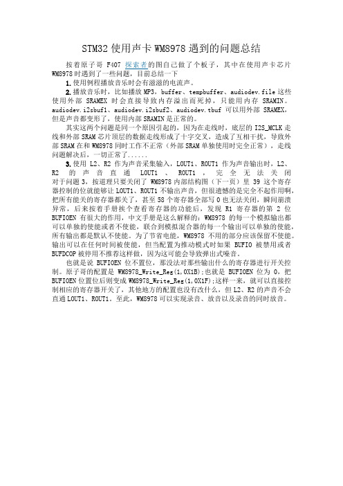
STM32使用声卡WM8978遇到的问题总结按着原子哥F407探索者的图自己做了个板子,其中在使用声卡芯片WM8978时遇到了一些问题,目前总结一下1.使用例程播放音乐时会有滋滋的电流声。
2.播放音乐时,比如播放MP3,buffer、tempbuffer、audiodev.file这些使用外部SRAMEX时会直接导致内存溢出而死掉,只能用内存SRAMIN。
audiodev.i2sbuf1、audiodev.i2sbuf2、audiodev.tbuf可以用外部SRAMEX,但是声音都变形了,使用内部SRAMIN是正常的。
其实这两个问题是同一个原因引起的,因为在走线时,底层的I2S_MCLK走线和外部SRAM芯片顶层的数据走线形成了十字交叉,造成了互相干扰,导致外部SRAM在和WM8978同时工作不正常(外部SRAM单独使用时完全正常),走线问题解决后,一切正常了......3.使用L2、R2作为声音采集输入,LOUT1、ROUT1作为声音输出时,L2、R2的声音直通LOUT1、ROUT1,完全无法关闭对于问题3,按道理只要关闭了 WM8978内部结构图(下一页)里 39 这个寄存器控制的位就能够让LOUT1、ROUT1不输出声音,但很遗憾的是完全不起作用啊,把所有能关的寄存器都关了,甚至58个寄存器全部写0也无法关闭,瞬间崩溃异常,后来按着手册挨个查看寄存器的功能后,发现R1寄存器的第2位BUFIOEN有很大的作用,中文手册是这么解释的:WM8978的每一个模拟输出都可以单独的使能或者不使能,联合到模拟混合器的每一个输出可以单独的使能,所有输出都是默认不使能。
为了节省电能,WM8978不用的部分应该保留不使能。
输出可以在任何时间被使能,但当配置为推动模式时如果BUFIO被禁用或者BUFDCOP被停用不推荐这样做,因为这可能会导致弹出式噪音。
也就是说BUFIOEN位不置位,那没法对那些输出什么的寄存器进行开关控制。
WM8978声卡同时录制与播放的ESP32代码
WM8978声卡同时录制与播放的ESP32代码本文档介绍了如何在ESP32上使用WM8978声卡实现同时录制和播放的功能。
硬件准备首先,确保你已经准备好以下硬件:- ESP32开发板- WM8978声卡模块- 适配器和电源线引脚连接将ESP32开发板与WM8978声卡模块进行正确的引脚连接。
以下是连接示意图:ESP32 WM8978--------------------GND GND5V VCCGPIO_NUM_X LRCKGPIO_NUM_Y BCKGPIO_NUM_Z DIN确保引脚连接正确,并确认WM8978声卡模块正常工作。
代码实现include "WM8978.h"void setup() {WM8978.begin();WM8978.setInputVolume(40, 40); // 设置输入音量WM8978.setOutputVolume(40); // 设置输出音量WM8978.micBiasEnable(); // 打开MIC偏置电压WM8978.inputRoute(WM8978.MICIN, WM8978.LINPUT); // 将MIC输入到左声道WM8978.inputRoute(WM8978.MICIN, WM8978.RINPUT); // 将MIC输入到右声道WM8978.outputRoute(WM8978.LINPUT, WM8978.LDAC); // 将左声道输出到LDACWM8978.outputRoute(WM8978.RINPUT, WM8978.RDAC); //将右声道输出到RDAC}void loop() {WM8978.recordStart(); // 开始录制delay(5000); // 持续录制5秒钟WM8978.recordStop(); // 停止录制WM8978.playStart(); // 播放录制的声音delay(5000); // 持续播放5秒钟WM8978.playStop(); // 停止播放}以上代码将通过WM8978库实现同时录制和播放功能。
WM8978声卡同时录音与播放的STM32程序
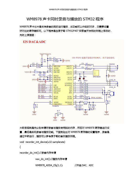
WM8978声卡同时录音与播放的STM32程序WM8978声卡芯片是支持录音的同时进行播放,该功能可以作实时对讲,只需要设置好对应的寄存器即可。
以下程序是在原子哥STM32F407探索者开发板的例程上修改的,先附上原理图:大致思路就是先分别申请好录音与播放使用到的内存,然后对WM8978寄存器进行设置,最后是实现录音与播放功能。
下面就贴出对WM8978寄存器的设置程序,录音是通过中断进行,播放可以参考原子哥的音乐播放例程。
void recorder_init_device(u32 samplerate){recorder_do_init();//录音内存申请wav_do_init();//播放内存申请WM8978_ADDA_Cfg(1,1); //开启DAC、ADCWM8978_Input_Cfg(1,0,0); //开启输入通道(MIC&LINE IN)WM8978_MIC_Gain(46); //MIC增益设置WM8978_Output_Cfg(1,0); //开启DAC输出 ,关闭BYPASS输出app_wm8978_volset(wm8978set.mvol);//输出声音WM8978_I2S_Cfg(2,0); //飞利浦标准,16位数据长度I2S2_Init(I2S_Standard_Phillips,I2S_Mode_MasterTx,I2S_CPOL_Low,I2S_DataFormat_16b); //飞利浦标准,主机发送,时钟低电平有效,16位帧长度I2S2ext_Init(I2S_Standard_Phillips,I2S_Mode_SlaveRx,I2S_CPOL_Low,I2S_D ataFormat_16b); //飞利浦标准,从机接收,时钟低电平有效,16位帧长度I2S2ext_RX_DMA_Init(i2srecbuf1,i2srecbuf2,I2S_RX_DMA_BUF_SIZE/2); //配置RX DMAI2S2_TX_DMA_Init(audiodev.i2sbuf1,audiodev.i2sbuf2,WAV_I2S_TX_DMA_B UFSIZE/2);//配置TX DMAi2s_tx_callback=wav_i2s_dma_tx_callback; //回调函数指向wav_i2s_dma_tx_callbacki2s_rx_callback=rec_i2s_dma_rx_callback;//回调函数指rec_i2s_dma_rx_callback//设置采样率等I2S_Play_Stop();I2S_Rec_Stop();I2S2_SampleRate_Set(samplerate);//录音采样率选择,默认选择22Khz录音I2S_Play_Start(); //开始I2S数据发送(主机)I2S_Rec_Start(); //开始I2S数据接收(从机)}。
- 1、下载文档前请自行甄别文档内容的完整性,平台不提供额外的编辑、内容补充、找答案等附加服务。
- 2、"仅部分预览"的文档,不可在线预览部分如存在完整性等问题,可反馈申请退款(可完整预览的文档不适用该条件!)。
- 3、如文档侵犯您的权益,请联系客服反馈,我们会尽快为您处理(人工客服工作时间:9:00-18:30)。
WM8978声卡同时录音与播放的STM32程序
WM8978声卡芯片是支持录音的同时进行播放,该功能可以作实时对讲,只需要设置
好对应的寄存器即可。
以下程序是在原子哥STM32F407探索者开发板的例程上修改的,先附上原理图:
大致思路就是先分别申请好录音与播放使用到的内存,然后对WM8978寄存器进行设置,最后是实现录音与播放功能。
下面就贴出对WM8978寄存器的设置程序,录音是通过中断进行,播放可以参考原子哥的音乐播放例程。
void recorder_init_device(u32 samplerate)
{
recorder_do_init();//录音内存申请
wav_do_init();//播放内存申请
WM8978_ADDA_Cfg(1,1); //开启DAC、ADC
WM8978_Input_Cfg(1,0,0); //开启输入通道(MIC&LINE IN)
WM8978_MIC_Gain(46); //MIC增益设置
WM8978_Output_Cfg(1,0); //开启DAC输出 ,关闭BYPASS输出
app_wm8978_volset(wm8978set.mvol);//输出声音
WM8978_I2S_Cfg(2,0); //飞利浦标准,16位数据长度I2S2_Init(I2S_Standard_Phillips,I2S_Mode_MasterTx,I2S_CPOL_Low,I2S_Dat
aFormat_16b); //飞利浦标准,主机发送,时钟低电平有效,16位帧长度
I2S2ext_Init(I2S_Standard_Phillips,I2S_Mode_SlaveRx,I2S_CPOL_Low,I2S_D ataFormat_16b); //飞利浦标准,从机接收,时钟低电平有效,16位帧长度I2S2ext_RX_DMA_Init(i2srecbuf1,i2srecbuf2,I2S_RX_DMA_BUF_SIZE/2); //配置RX DMA
I2S2_TX_DMA_Init(audiodev.i2sbuf1,audiodev.i2sbuf2,WAV_I2S_TX_DMA_B UFSIZE/2);//配置TX DMA
i2s_tx_callback=wav_i2s_dma_tx_callback; //回调函数指向wav_i2s_dma_tx_callback
i2s_rx_callback=rec_i2s_dma_rx_callback;//回调函数指
rec_i2s_dma_rx_callback
//设置采样率等
I2S_Play_Stop();
I2S_Rec_Stop();
I2S2_SampleRate_Set(samplerate);//录音采样率选择,默认选择22Khz录音
I2S_Play_Start(); //开始I2S数据发送(主机)
I2S_Rec_Start(); //开始I2S数据接收(从机)
}。