普通压力开关设置说明
压力开关设置方法

压力开关设置方法
压力开关是一种能根据压力变化切换电路的开关装置。
它常用于控制液体或气体管路中的压力,当压力超过或低于设定值时,开关会自动切换电路,从而控制相关设备的运行。
以下是一种常见的压力开关设置方法:
1. 确定设定值:根据管路中液体或气体的工作压力范围,确定需要设置的开关压力的设定值。
2. 将压力开关安装在管路中:根据管路的实际情况,选择合适的安装位置,并通过管道接头将压力开关连接到管路中。
3. 调整压力开关设定值:根据设定值确定的压力范围,使用压力调整螺钉或旋钮,逐步调整压力开关的设定值。
通常,顺时针旋转可增加设定值,逆时针旋转可减小设定值。
4. 进行测试和调整:在设定值调整完成后,进行实际测试。
通过增加或减小压力,观察开关的切换情况,确保开关在设定的压力范围内正常工作。
5. 固定和封闭:确认调整完毕后,将压力开关固定在安装位置,并进行密封处理,以防止液体或气体泄漏。
需要注意的是,压力开关的安装和调整应根据具体的设备和压力要求进行操作,以确保其正常、稳定的工作。
如果不熟悉操作或存在风险,建议请专业人士进行安装和调整。
压力开关调节方法
压力开关调节方法
在以下内容中,我们将讨论压力开关的调节方法,以实现准确和可靠的压力控制。
首先,确认压力开关所用于的应用。
不同的应用可能需要不同的压力范围和精度。
确定所需的压力范围将有助于我们进行正确的调节。
然后,准备一个压降器和一个压力表。
这些工具将帮助我们进行准确的调节。
接下来,将压降器连接到压力开关上。
通过调节压降器的设置,可以限制进入压力开关的压力。
将压力表连接到压降器的出口,以便监测并记录压力值。
现在,我们可以开始调节压力开关了。
首先,将压力开关的微调旋钮调到最低压力位置,以确保开关处于关闭状态。
然后,逐步增加压降器的设置,直到达到所需的最低工作压力。
此时,压力开关应该被打开,允许流体通过。
测试开关是否可靠。
通过增加或减小所施加到压力开关上的压力,观察开关的行为。
确保它能够准确地在所需的压力范围内打开和关闭。
如果发现开关的动作没有按预期进行,可以使用微调旋钮进行微小的调整,以改变开关的敏感度和动作点。
重复以上步骤,直到压力开关在所需的压力范围内稳定地运行。
最后,将压力表和压降器从系统中移除,并重新检查一次压力开关的功能。
确保其仍然能够正确地响应压力的变化。
这些是调节压力开关的一般步骤。
请注意,不同的压力开关可能有不同的调节方法和要求。
因此,在进行调节之前,请参考所使用的压力开关的操作手册或厂家说明书,并按照其指导进行操作。
压力开关设定标准版资料
按下S2就显示出压力单位BAR,再按下S1就显示出压力单位PSI,然后按S1可以 进行压力单位的选择,选择完之后按一下S2就退回到单位初始界面.
பைடு நூலகம்
在显示UNIT界面时按两下S1就到了SET界面,按一下S2进入数值设置界面,PSI单位整数位为四位,BAR单位的整数位为三位数,小数 点后有一位。
如果要设置密码按一下S2选择YES. 首先在单位里设定bar,在s1里设定大于120bar(不能太大根据实际需求,压力开关也有量程范围限定)。 由设置高低电平界面按两下S1到r1界面,和上面设置一样方法调到需要的数值。 如3400T冲压模具需要120bar压力保护,低于120bar报警(机器中检测到有输入信号ok,没输入信号报警)。 这里不对密码保护介绍,想做密码保护的请参考说明书. 如3400T冲压模具需要120bar压力保护,低于120bar报警(机器中检测到有输入信号ok,没输入信号报警)。 如果要设置密码按一下S2选择YES. 按S2可以在不同的位数更改,当停在要更改的位数时按S1进行数值大小的变更,更改后按S2会返回S1界面
如果要设置密码按按下一下SS12到选择图Y中ES.第一个界面,这里设置输出信号高低电平的,PNP 按下两次S1就与到单N位P界N面
由设置高低电平界面按两下S1到r1界面,和上面设置一样方法调到需要的数 值。
设置好r1后按数次S1键就到了储存界面,选择YES保存进去就可以了。
如3400T冲压模具需要120bar压力保护,低于120bar报警 (机器中检测到有输入信号ok,没输入信号报警)。
首先在单位里设定bar,在s1里设定大于120bar(不能太大根 据实际需求,压力开关也有量程范围限定)。
在r1里设定为120bar.输出为常开点,PNP。
压力开关调节方法

压力开关调节方法压力开关是一种用于控制压缩机启停的重要设备,它能够根据系统压力的变化来控制压缩机的运行,从而保证系统的正常运行并避免过载。
正确的调节压力开关对于系统的稳定运行至关重要。
下面将介绍一些常见的压力开关调节方法,希望能对大家有所帮助。
首先,调节压力开关之前需要确保系统处于安全状态,压缩机已经停机并且系统压力已经完全释放。
接下来,可以按照以下步骤进行调节:1. 确定压力开关的工作范围,根据压力开关的规格和系统的工作要求,确定压力开关的工作范围。
通常情况下,压力开关会有一个最小压力和最大压力范围,需要根据实际情况来进行调节。
2. 调节压力开关的切换压力,使用专用的调节工具,可以逐步调节压力开关的切换压力。
在调节过程中,需要不断地监测系统的压力变化,并根据需要进行微调,直到达到所需的切换压力为止。
3. 调节差动压力,有些压力开关还具有差动压力的调节功能,可以通过调节差动压力来控制压缩机的启停频率。
在调节差动压力时,需要根据系统的实际工作情况来确定最佳的差动压力数值。
4. 测试和确认,在完成压力开关的调节之后,需要对系统进行测试,确保压力开关能够准确地控制压缩机的启停,并且系统的压力稳定在设定的范围内。
如果测试结果不理想,需要重新进行调节,直到达到预期的效果为止。
需要注意的是,在进行压力开关的调节过程中,一定要小心谨慎,避免造成系统的损坏或者安全事故。
另外,建议定期对压力开关进行检查和维护,确保其工作正常可靠。
总之,正确的调节压力开关对于系统的稳定运行至关重要。
通过以上介绍的调节方法,相信大家能够更好地掌握压力开关的调节技巧,保证系统的正常运行和安全性。
希望本文对大家有所帮助,谢谢阅读!。
压力开关设置方法

压力开关设置方法压力开关是一种用于控制和保护压力设备的电气开关设备,广泛应用于空压机、泵浦、供水设备、制冷和空调设备等工业和家用设备中。
通过对压力开关进行设置,可以实现设备的安全工作和自动控制。
下面将详细介绍压力开关的设置方法。
一、压力开关的工作原理压力开关主要由调节弹簧、压力调节螺母和开关机构组成。
当被控制的设备运行时,设备内部产生压力,当压力达到预设值时,压力作用在压力开关的调节弹簧上,使其产生形变。
当形变超过设定值时,调节弹簧会推动开关机构,从而实现开关的闭合或断开。
这样就能够控制设备的运行状态。
二、压力开关的设置步骤1. 确定设备的工作压力范围:在设置压力开关之前,首先需要了解设备的工作压力范围。
可以通过设备的工作手册或技术规格表来了解设备的额定工作压力和最大工作压力。
2. 选择合适的压力开关型号:根据设备的工作压力范围选择合适的压力开关型号。
一般来说,压力开关的额定工作压力应该大于设备的最大工作压力,以保证设备正常运行。
3. 调节开关压力:将压力开关安装在设备上,通过调节压力调节螺母将开关的压力调节到设备所需的工作压力。
调节时可以使用专用的调节工具,逐渐调节螺母,直到达到所需的工作压力。
4. 调节压力差:压力差是指压力开关在开启和关闭状态之间的压力差值。
通过调节压力调节螺母,可以调节压力开关的压力差。
一般情况下,设备需要在达到最小工作压力和最大工作压力之间切换,此时需要调节压力差。
5. 检查压力开关的工作状态:设置完成后,需要对压力开关进行检查,确保其能够正常工作。
可以通过手动加压或减压来观察开关的闭合和断开状态,并在调整过程中进行必要的调整。
6. 定期检查和维护:一旦完成设置,就需要定期检查和维护压力开关。
这包括清洁压力开关的外部和内部,检查调节弹簧和开关机构的正常运行,以及根据设备的使用情况进行必要的调整。
三、注意事项1. 安全操作:在设置压力开关时,必须注意安全操作,关闭设备电源,并使用绝缘手套和工具进行操作,以避免电击和其他安全事故的发生。
SMC IS10-SMW02EN 普通开关型压力开关说明书
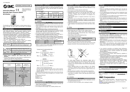
IS10-SMW02ENPage 1 of 1Instruction ManualNormally Open Pressure Switch IS10 SeriesThe intended use of the Pressure Switch is to detect pressure above or below a set value. The user is able to set the value in the specified range.1 Safety InstructionsThese safety instructions are intended to prevent hazardous situations and/or equipment damage. These instructions indicate the level of potential hazard with the labels of “Caution,” “Warning” or “Danger.”They are all important notes for safety and must be followed in addition to International Standards (ISO/IEC) *1), and other safety regulations. *1)ISO 4414: Pneumatic fluid power - General rules relating to systems. ISO 4413: Hydraulic fluid power - General rules relating to systems.IEC 60204-1: Safety of machinery - Electrical equipment of machines. (Part 1: General requirements)ISO 10218-1: Manipulating industrial robots -Safety. etc.∙ Refer to product catalogue, Operation Manual and Handling Precautions for SMC Products for additional information.not avoided, will result in death or serious injury.Warning∙ Always ensure compliance with relevant safety laws and standards.∙ All work must be carried out in a safe manner by a qualified person in compliance with applicable national regulations∙ System reaction time is to be determined by the machine builder2 Specificationsthe valve occurred (pulse shape: sine wave). Pulse time 11 ms.2 Specifications - continuedNOTE 2) No malfunction occurred in a sweep cycle test between 10 to 150 Hz at vibration sweep 0.35mm. The test was performed in the three axes and two directions, 7 min per cycle (20 cycles). For further test details contact SMC.3 Installation3.1 InstallationWarning∙ Do not install the product unless the safety instructions have been read and understood.∙ When handling the product, hold the body and do not apply tensile stress to the power supply cable. Otherwise, damage may occur to the product.∙ Avoid repeatedly bending or stretching the lead wire.Wiring which applies repeated bending and tensile stress to the lead wire can break the circuit. If the lead wire is damaged, causing operation failure, replace the product with a new one.∙ Do not drop or subject the product to impacts when handling.∙ Connect load before connecting with power source. The switch is instantaneously damaged when the load is not connected.∙ Make the wiring length as short as possible. When the load which is operated by the pressure switch is an inductive load, or the lead wire is 5 m or longer, use the contact protection box NOTE1 shown in the table below. Otherwise, damage to the switch can result. NOTE 1: In case of use in safety related application do not use the contact protection box CD-P11 or CD-P12• Internal circuit of contact protection box• How to connect contact protection boxConnect the lead wires from the body and the contact protective box side indicated “SWITCH.” Make the lead wire as short as possible, within 1 m.∙ Check the wiring for possible short circuits. If some of the wires are short circuited, the switch may be damaged due to excessive current flow.∙ Dimensions of lead wire Enclosure: ø 3.4 Insulator: ø 1.1 Conductor: ø 0.643.2 EnvironmentWarning∙ Do not use in an environment where corrosive gases, chemicals, salt water or steam are present.∙ Do not use in an explosive atmosphere.∙ Do not expose to direct sunlight. Use a suitable protective cover.3 Installation - continued∙ Do not install in a location subject to vibration or impact in excess of the specification. Excessive vibration may cause malfunction or may incorrect setting.∙ Do not mount in a location exposed to radiant heat.∙ Do not apply vacuum. If this occurs this may result in breakage.∙ Applicable fluid is limited to air and inert gas. Other fluids are not acceptable. Especially, never use flammable fluid and gas, which may result in explosion since the product is not designed to be explosion-proof.∙ Avoid using the switch in a magnetic environment. It may cause a malfunction.∙ Do not use in such an environment, where water or oil is splashed. Since it is the open type construction, if water or oil enters into the internal parts, the electric circuit will be corroded and may result in a malfunction or damage.∙ Supply the pressure for the product continuously to operate a switch. If the increasing or decreasing pressure is slow, there will be “stick -slip”. 3.3 PipingCaution∙ Before piping make sure to clean up chips, cutting oil, dust etc.∙ When installing piping or fittings, ensure sealant material does not enter inside the port. When using seal tape, leave 1 thread exposed on the end of the pipe/fitting.∙ Tighten fittings to the specified tightening torque. Recommended tightening torque:∙ Apply a wrench to the bottom of the product when screwing.Turning it by applying a wrench on the top of the main body may cause damage to the product. Recommended tightening torque: 7 to 9 N·m∙ To screw piping materials into components, tighten with a recommended tightening torque while holding the female thread side. If the minimum tightening torque is not observed, this can cause clearance in the connection between male and female fittings leading to seal leakage.∙ Excess tightening torque can cause damage to the threads. Furthermore, tightening without holding the female thread side can cause damage due to the excess force that is applied directly to the bracket.∙ Mounting direction is available in either horizontal or perpendicular. ∙ This product (IS10 series) uses a reed switch. If the chattering of the output signal is a problem, choose a solid state type pressure switch or adjust by PLC.3.4 LubricationCaution∙ SMC products have been lubricated for life at manufacture, and do not require lubrication in service.∙ If a lubricant is used in the system, refer to catalogue for details.4 Settings∙ Please set the product within the range of the display pressure in the scale plate.∙ There is a possibility that defective operation and a set gap are generated when outside of the range of the display pressure and setting pressure.∙ Turn the adjusting screw and place the red line of adjustment screw in line with the marking on the scale plate. Turn clockwise to adjust for high pressure.∙ Use a screwdriver of a size suitable for the head of adjustment screw. ∙ The scale displays the value for the off pressure.∙ When detecting the ON-pressure signal, note that set pressure on scale plate plus ON-OFF differential (Hysteresis) will be ON-pressure signal.∙ Pressure display on the scale plate is just as a reference guide. For an accurate setting, measure it by pressure gauge.5 How to Order∙ Please refer to the catalogue.6 Outline Dimensions (mm)∙ Please refer to the catalogue.7 Maintenance7.1 General MaintenanceCaution∙ Not following proper maintenance procedures could cause the product to malfunction and lead to equipment damage. ∙ If handled improperly, compressed air can be dangerous.Maintenance of pneumatic systems should be performed only by qualified personnel.∙ Before performing maintenance, turn off the power supply and be sure to cut off the supply pressure. Confirm that the air is released to atmosphere.∙ After installation and maintenance, apply operating pressure and power to the equipment and perform appropriate functional and leakage tests to make sure the equipment is installed correctly.∙ If any electrical connections are disturbed during maintenance, ensure they are reconnected correctly and safety checks are carried out as required to ensure continued compliance with applicable national regulations.∙ Do not make any modification to the product.∙ Do not disassemble the product, unless required by installation or maintenance instructions.∙ Perform periodic inspections to ensure proper operation of the switch. Verifying the operation of the switch on a regular basis can minimize unexpected problems with a machine or equipment.∙ Wear safety glasses when conducting periodic inspections.∙ Take precautions when using a switch for an interlock circuit. When a pressure switch is used for an interlock circuit, devise a multiple interlock system to prevent trouble or malfunction. Verify the operation of the switch and interlock function on a regular basis.∙ Ensure there is enough space around the product to carry out maintenance.8 Limitations of Use8.1 Limited warranty and Disclaimer/Compliance Requirements Refer to Handling Precautions for SMC Products.9 ContactsRefer to Declaration of Conformity and for contacts.URL : http// (Global) http// (Europe) 'SMC Corporation, Akihabara UDX15F, 4-14-1, Sotokanda, Chiyoda-ku, Tokyo 101 0021Specifications are subject to change without prior notice from the manufacturer. © 2018 SMC Corporation All Rights Reserved. Template DKP50047-F-085HORIGINAL INSTRUCTIONSRefer to Declaration of Conformity for relevant Directives。
压力开关的调试方法
压力开关的调试方法压力开关是工业自动化控制系统中常用的一种开关装置,它可以根据管路中液体或气体的压力变化来实现电路的开闭。
在实际应用中,压力开关的调试显得尤为重要,因为它直接影响到整个控制系统的稳定性和可靠性。
本文将从以下几个方面详细介绍压力开关的调试方法。
一、检查电源和线路在进行压力开关调试之前,需要先检查电源和线路是否正常。
首先要检查电源是否接通,并且电压是否稳定;其次要检查线路是否连接正确,是否有松动或接触不良等问题。
如果发现电源或线路存在问题,需要及时排除故障。
二、设置合适的压力值在进行压力开关调试时,需要先设置合适的压力值。
这个值应该根据具体情况来确定,一般可以参考设备说明书或者咨询生产厂家。
如果没有相关资料可供参考,可以根据实际需求来设置一个合理的值。
三、检查机械部分在进行压力开关调试之前,还需要对机械部分进行检查。
首先要检查机械部分是否安装正确,是否有松动或变形等问题;其次要检查机械部分的灵敏度是否符合要求,可以通过手动操作来测试。
四、调整电气参数在完成上述步骤之后,就可以开始进行电气参数的调整了。
首先要确定压力开关的触发点和复位点,这个可以通过手动操作来测试;其次要调整触发点和复位点的误差范围,使其达到最佳状态。
五、测试压力开关在完成以上步骤之后,需要对压力开关进行全面测试。
首先要测试压力开关的响应速度和稳定性,可以通过改变压力值来进行测试;其次要测试压力开关的重复性和精度,可以通过多次测试来验证。
六、记录数据和问题在完成所有测试之后,需要将数据记录下来,并且对存在的问题进行总结。
如果发现存在问题,需要及时采取措施进行修复或更换。
七、定期维护在完成以上步骤之后,还需要定期对压力开关进行维护。
这个包括清洗机械部分、检查线路连接、校准电气参数等方面。
只有定期维护才能保证设备长期稳定运行。
总结:以上就是压力开关的调试方法,通过以上步骤可以保证压力开关的稳定性和可靠性。
在实际应用中,还需要结合具体情况进行调整和优化。
压力开关怎么调
压力开关怎么调
要调节压力开关,首先要先确定所需的压力范围。
然后根据调节要求,按照以下步骤操作:
1. 断开电源:首先断开电源,确保操作的安全性。
2. 打开调节螺丝:使用合适的工具,如螺丝刀,打开压力开关上的调节螺丝,逆时针旋转螺丝,直到螺丝松开。
3. 调节压力:根据所需的压力范围,顺时针旋转调节螺丝,增加压力;逆时针旋转调节螺丝,减小压力。
可以根据压力表的读数来进行调节。
4. 固定调节螺丝:调节到所需的压力后,使用螺丝刀顺时针旋转调节螺丝,锁定螺丝,固定在设定的位置。
5. 检查:确保调节完毕后,进行功能检查,确保压力开关能够正常工作。
6. 重新上电:最后,重新连接电源,确认压力开关能够正常运作。
请注意,压力开关的调节可能因厂家和型号而有所不同,以上步骤仅供参考,请根据具体的压力开关说明书进行调节。
如果不熟悉操作或有安全疑虑,请寻求专
业人士的帮助。
压力开关调节方法
数控机气路压力开关调节方法目前,我公司共使用四种型号的压力保护开关,分别是SMC的IS1000机械压力开关、GP46机械压力表带压力开关、ISE30型数显压力表压力开关和CKD的PPX型数显压力表压力开关。
一、各种压力开关的设定方法1、IS1000机械压力开关出线的一侧有一个小的旋钮,使用小一字螺丝刀通过调节此旋钮即可改变开关动作的压力值。
在压力开关一侧有一个红色的指示器,可以指示当前的压力设定值。
2、GP46压力表带压力开关设定动作压力是需要逆时针旋转取下压力表的透明保护罩,在压力表盘的下方有一个小的旋钮,使用小一字螺丝刀调节此旋钮即可调节压力开关的动作压力。
压力表上有一个绿色指针,此指针指示设定的动作压力。
注意在调好动作压力之后将压力表的保护罩再装上去。
说明:由于IS1000和GP46属于机械式压力开关,所以他们的动作压力指示器会存在0.05MPa以下的指示误差,还会存在0.08MPa的动作迟滞。
3、ISE30型数显压力表压力开关共有三个按键和一个显示窗口,三个按键分别为“△”、“SET”、“▽”,通过这三个按键可实现压力开关的设置。
持续按“SET”三秒以上即可进入主程序设置,第一个界面是选择压力单位,一般设置为“bar”,如果需要改变单位,通过“△”或 “▽”来改变。
设置到需要的单位后按“SET”进入下一级显示颜色设置。
显示颜色一般设置为“SOG”(ON时为绿色),如果要改变显示颜色同样是通过△”或 “▽”来改变。
显示颜色设置完成后按“SET”进入动作模式设定,一般设置为“HYS”(迟滞模式),继续按“SET”进入输出状态设定,一般设置为“NO”(常开状态)。
继续按“SET”进入响应时间设定,这里设置气压达到设置压力和输出动作信号之间的延时,单位为毫秒。
继续按“SET”进入自动预置设定,一般设置为“MAN”(手动模式,不能设置为“AUT”)。
再继续按“SET”退出主程序设置。
按一下“SET”会出现“P_1”和一个数字的交替闪烁,此数字即为压力开关的动作压力,按“△”或 “▽”可进入动作压力P值的设置界面,显示区显示压力值,且最后一位闪烁,此时通过“△”或 “▽”可以改变最后一位置,通过“SET”可以在不同数字位之间切换,再通过“△”或 “▽”改变当前闪烁的数字位的值。
压力开关调节方法
压力开关调节方法压力开关是一种用于控制液压系统中压力的重要元件,它的调节对于系统的正常运行至关重要。
在使用压力开关时,正确的调节方法能够确保系统的稳定性和安全性,提高设备的工作效率。
下面将介绍几种常见的压力开关调节方法。
首先,调节压力开关的步骤如下:1. 确定调节范围,在调节压力开关之前,首先需要确定系统所需的工作压力范围。
这可以通过查阅设备的技术资料或者咨询厂家来确定。
在调节压力开关时,应该将其调节在设备所需的工作压力范围内。
2. 使用专用工具,在调节压力开关时,需要使用专用的调压工具,如压力表、扳手等。
这些工具能够帮助我们准确地调节压力开关,确保其达到设定的工作压力。
3. 小心调节,在调节压力开关时,需要小心操作,避免过度调节或者调节不足。
过度调节会导致系统压力过高,从而影响设备的正常运行,而调节不足则会导致系统无法达到所需的工作压力。
其次,根据不同类型的压力开关,其调节方法也会有所不同:1. 调节螺栓,对于一些手动调节的压力开关,通常可以通过旋转螺栓来调节其工作压力。
在调节时,需要先松开锁紧螺母,然后通过旋转螺栓来调节压力开关的工作压力,最后再将锁紧螺母固定住。
2. 调节旋钮,对于一些电子调节的压力开关,通常会配有旋钮来进行调节。
在调节时,需要根据设备的工作压力范围,通过旋转旋钮来调节压力开关的工作压力,直到达到所需的数值。
最后,调节完压力开关后,需要进行一些必要的检查和测试:1. 检查压力表,在调节完压力开关后,需要使用压力表来检查系统的工作压力是否达到设定值。
如果工作压力不正常,需要重新调节压力开关,直到达到设定的工作压力范围。
2. 进行测试,在调节完压力开关后,需要进行一些系统的测试,以确保系统的稳定性和安全性。
通过对系统进行负载测试和过载测试,可以验证压力开关的调节效果。
综上所述,正确的压力开关调节方法能够确保系统的正常运行和设备的安全性。
在调节压力开关时,需要根据设备的工作压力范围,使用专用工具进行小心调节,最后进行必要的检查和测试。
- 1、下载文档前请自行甄别文档内容的完整性,平台不提供额外的编辑、内容补充、找答案等附加服务。
- 2、"仅部分预览"的文档,不可在线预览部分如存在完整性等问题,可反馈申请退款(可完整预览的文档不适用该条件!)。
- 3、如文档侵犯您的权益,请联系客服反馈,我们会尽快为您处理(人工客服工作时间:9:00-18:30)。
PK系列压力开关设置说明
接线图如图所示:
出厂压力如图所示:
左边指针所示刻度为压差(0.2 Mpa)
右边指针所示刻度为定点压力(0.3 Mpa)
工作原理:当工作压力≤0.1 Mpa 时触点1和5 接通
当工作压力≥0.3 Mpa 时触点1和3接通
客户使用情况分析:
定点压力:0.35 mpa; 压差0.05mpa
需要压力范围:0.3 mpa-0.35mpa
开关接线方式:2根导线分别接在1、5 触点
压力开关作用:油路压力低于0.3mpa 报警。
压力开关所装在系统工作原理:油箱1→油泵1→减压阀(过滤器)→压力开关→压力调节阀→所需润滑工件→油泵2→油箱1。
工作环境为闭环,油泵最高工作压力0.5mpa。
情况分析:
1:工作压力低于0.3mpa 不报警。
建议压力开关设置:PK506定点压力设定0.4 Mpa,压差0.1mpa,当工作压力≤0.3mpa时1-5触点接通。
PK510定点压力设定0.5 Mpa,压差0.2mpa,当工作压力≤0.3mpa时1-5触点接通。