海上超深水采油技术
世界深水油气田水下技术应用研究

统开发, 平静的海底为水下生产设施提供了良好的
相泵组, 电力由 Gullfaks C 平台提供。
响, 而且节约了大量投资, 对高纬度寒冷地区油气
井口回压, Statoil 公司预计能够把采收率从 49%提
低温海底输送湿天然气, 通过井口加注防冻液降低
1 2 北极地区水下井口回接距离最长的深水气田
度传感器和湿气流量计等。
Fig 1 Subsea production system of Tordis Oilfield
除砂器, 与回注水一起注入地层, 特殊情况下也可
上设有远程控制阀门, 阀门直径较大, 可保证天然
该海域受大西洋暖流影响常年不结冰, 但是海
以与油气一起混输到 Gullfaks C 平台进一步处理。
shore oil and gas fields In⁃depth analysis has been conducted on eight typical oil and gas fields for application of
subsea technologies, including Tordis, Snohvit, BC - 10 ( Parque das Conchas ) , Cascade⁃Chinook, Perdido,
1 深水油气田水下技术进展及应用
1 个采用全水下系统开发的海上气田。 该气田没有
1 1 世界 第 1 座 采 用 水 下 分 离 增 压 技 术 的 油 田
———Tordis
[3]
Tordis 油 田 位 于 北 海 挪 威 一 侧 Tampen 区 的
34 / 7 区块内, Statoil 公司拥有 28 22% 权益并担任
油气工程技术发展到今天, 已经形成了很多分支,
海洋石油深水钻完井技术措施
海洋石油深水钻完井技术措施随着全球能源需求的不断增长,海洋石油的开发已成为人们关注的热点之一。
而深水油田的开发更是海洋石油开发中的一大挑战,因为深水条件下的石油开采和完井技术要求更高,成本更大。
本文将重点介绍海洋石油深水钻井完井技术措施。
一、深水钻井完井技术要求1.水深要求深水钻井一般指水深超过500米的区域,500-1500米为中水深钻井,超过1500米为深水钻井。
由于深水区域的水深较大,风浪和洋流的影响较小,因此深水钻井完井的技术要求较高。
2.环境条件要求深水区域的环境条件十分恶劣,海底水深,海流湍急,海底温度低,而且还存在着飓风、沙尘暴等极端天气,对钻井作业的安全性和可靠性提出了更高的要求。
3.技术难度要求深水区域的地质情况复杂,地下石油资源分布不均,水平分布广泛,开采难度大,深水钻井完井技术的难度也就更大。
二、深水钻井完井技术措施1.钻井平台选择深水区域的钻井平台要求比较苛刻,一般有浮式钻井平台、半潜式钻井平台和固定式钻井平台等,根据实际情况选择合适的钻井平台模式,以满足深水钻井作业的需求。
2.井眼稳定措施深水钻井井眼稳定是深水钻井完井中的一项关键技术,包括对井眼的泥浆配方、井眼的支撑和防护等技术措施,以确保井眼在钻井和完井过程中保持稳定。
3.井眼冲洗技术深水钻井完井中,井眼冲洗技术是必不可少的一项工艺,通过冲洗井眼可以清除井底碎屑、减轻井眼摩阻,提高钻井速度和井眼质量。
4.钻头选择深水钻井中,选择合适的钻头是十分重要的,在深水区域,一般使用可控方向钻头和导向钻头等,以满足深水井眼质量和完井效果的要求。
5.完井工艺技术深水完井技术主要关注几个方面:封隔技术、井筒治理技术、水泥浆配方、井眼净化技术等,这些技术对于深水油田的开发至关重要。
6.安全与环保技术深水油田开发中,要严格把控环境保护和安全生产,尤其是深水油田的开发,更要注重安全和环保,加强对海洋环境的保护。
7.智能化技术在深水钻井完井中,智能化技术是未来的发展方向,包括智能化钻井井下设备、智能化井筒监测系统等,提高深水钻井的效率和安全性。
超深水油气田开发中的海上天然气开采技术探索

超深水油气田开发中的海上天然气开采技术探索在全球能源需求快速增长的背景下,海上石油与天然气资源的开采已成为当今能源行业的重要课题之一。
随着陆地油气资源的逐渐枯竭,人们开始转向海洋深处寻找新的能源来源。
超深水油气田开发中的海上天然气开采技术正是应对这一挑战的重要手段之一。
超深水油气田开发中的海上天然气开采技术探索旨在解决海底水深数千米甚至上万米的情况下,如何高效、安全地开采天然气的问题。
这对于海洋工程师和石油公司来说是一项巨大的挑战,需要他们借助先进的技术和设备来实现。
首先,海上天然气开采技术探索中,深水开发技术是关键。
深水开采是指在水深超过500米的海域进行油气开采。
为了实现深水开采,石油公司需要应用先进的技术来处理深水环境带来的各种问题,如海底流体温度和压力的改变,以及海洋环境对设备和管道的影响。
在深水开采过程中,需要使用钻井设备、生产平台、管道输送等技术,以确保油气能够从海底成功开采上来。
其次,探明天然气储量是超深水油气田开发中的一项重要任务。
海上天然气开采需要事先确定合适的开采区域,这需要进行大量的地质勘探和海洋地质调查。
石油公司通过使用船舶、潜水器等工具进行勘探,结合地质数据和测量结果,确定潜在的天然气矿藏。
在深水开采中,由于水深较大,地质勘探和采样变得更加困难,然而探明储量的准确性对于后续的开采工作至关重要。
此外,超深水油气田开发中的海上天然气开采技术探索还需要解决海底设备的可靠性和安全性问题。
由于离岸环境的恶劣性质,海底设备需要经受高压、低温、海洋腐蚀等多重挑战。
因此,研发和应用高强度、耐腐蚀的材料,设计可靠的设备结构和工艺,以及建立健全的安全管理体系,都是确保海上天然气开采的关键要素之一。
同时,加强风险评估和应急响应能力,以防范潜在的事故和灾害,也是十分重要的。
最后,超深水油气田开发中的海上天然气开采技术探索需要在环保和可持续发展的基础上进行。
石油公司和海洋工程师在开采过程中必须遵守环保法规,努力减少环境污染。
海洋油气开采原理与技术
海洋油气开采原理与技术
海洋油气开采原理与技术是指利用各种技术手段和设备,在海洋中开采石油和天然气资源的过程。
其原理和技术主要包括以下几个方面:
1. 勘探与开发:海洋油气开采首先需要进行勘探工作,通过地质勘探、地球物理勘探和地球化学勘探等手段,确定油气资源的存在性和分布规律。
然后根据勘探结果,选择合适的开发方式,如常规油气田开发、深水油气田开发、深海油气田开发等。
2. 钻井:钻井是油气开采的关键技术之一,通过钻井设备将钻头钻入地下油气层,获取油气资源。
海洋油气钻井主要包括海上钻井平台、定向钻井、水平井等技术。
3. 采油与采气:采油和采气是指通过各种技术手段将地下油气资源提取到地面的过程。
海洋油气开采中常用的方法包括自然流动开采、人工提高注水开采、压裂等技术。
4. 输送与储存:海洋油气开采后,需要将油气输送到陆地加工厂进行处理。
海洋油气输送主要依靠海底管道、船舶运输等方式。
另外,还需要设计建设储存设施,如油气储罐、储存船等。
5. 安全与环保:海洋油气开采过程中,需严格控制安全风险,防止事故发生。
同时,还需重视环境保护,避免油气开采对海洋生态环境造成不可逆转的影响,采取相应的环境监测和治理措施。
海洋油气开采涉及多个学科领域,如地质学、地球物理学、石油工程学、海洋工程学等。
随着技术的不断发展和创新,海洋油气开采技术也在不断进步,为海洋石油和天然气资源的有效开发和利用提供了技术支持。
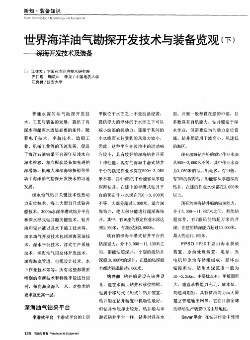
世界海洋油气勘探开发技术与装备览观(下)——深海开发技术及装备
间,都能钻超深井 ,个别的能钻井
深超1,0米的深井;在建的钻深能 000 力都达到或超过900 ,0米。 钻 井船 钻 井船是 设有钻井 设 备 ,能在水面上钻井和移位的船 ,
也属于移动式 ( 船式 )钻井装置 。 钻井船在钻井装置中机动性最好 ,
平 台的额定作业水深在5 0 , 5 0  ̄3 0 0
面 。井架一般都设在船 的中部 ,且
多数具有 自航能力。钻井船适 于深
水作业 ,但需要适当的动力定位设 施 。钻井船适用于波高小、风速低
的海区 。
着 电子 技术 、 宇航 技 术 、造 船 工 业 、机械工业等 的飞速发展 ,促进 了海洋石 油钻采平 台逐年从浅水 向
加严格 ;工艺流程在确保顺畅 的同
时 ,重要模块 的布局要顺应船体运
技术 。现 已研究 出一些 防疲劳技术
( 图2 ) 。 如 7
动要求并 留足维修空间 ;具有 比陆 上集成化更高、配置更完备的 自动
化控制系统。
多相位 系统 的抑 制剂 注射
化学剂注入要保证流量的稳定, 优 化化 学 剂 注 入方 法 显 得额 外 重
下供热 中心和水下增 压气 站 ,最后 到路上终端。
3 68W(,0h ),而20年交付 ,7k 5O0 p 05
的钻井绞车功率最高达到了50 5W ,7k
(,0 h ),十几年的时间增加了 6 90 p
电缆防疲劳技术
海洋油气开发中,平台上以及海 水里的勘探开发设施 的导线 ,电缆
会 因为时间和 海水的原因 ,出现疲
3 倍多,可见其发展速度之快。
油气处理系统 Fபைடு நூலகம்S的油气处理 PO
深水勘探探索深水油气资源开发的挑战与机遇
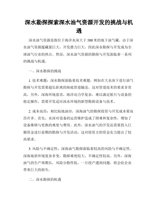
深水勘探探索深水油气资源开发的挑战与机遇深水油气资源是指位于海洋水深大于500米的地下油气藏。
由于深水油气资源蕴藏量巨大,开发潜力巨大,因此深水勘探与开发成为全球油气行业的热点。
然而,深水油气资源的勘探与开发面临着一系列的挑战与机遇。
一、深水勘探的挑战1. 技术难题:深水勘探面临着技术难题,例如在大水深下进行油气勘探与开发需要超长距离的海底管道输送,这对管道技术的要求非常高。
另外,深海环境恶劣,海洋动力学复杂,难以满足船只与设备的稳定操作,需要开发适应深水环境的新型勘探设备与技术。
2. 成本高昂:相比陆地油田,深海油气的勘探投资与开发成本要高昂许多。
首先,水深对设备的运营维护造成了困难和复杂性,增加了设备维修与更换的难度与费用。
此外,深水油气的开发还需要投入巨额资金进行前期的勘探与开发活动,这对投资方的资金实力提出了较高要求。
3. 风险与不确定性:深海油气勘探面临着较高的风险与不确定性。
深海地质环境复杂多变,勘探难度较大,不确定性较高。
另外,深海油气的生产周期长,风险分散性低,一旦投产遇到问题,将会给企业带来巨大的损失。
二、深水勘探的机遇1. 蕴藏量丰富:深水油气资源蕴藏量巨大。
根据国际能源署的数据显示,目前全球已发现的深海油气资源占全球未被开发的油气资源的70%以上,具有巨大的市场价值与开发潜力。
深水油气资源的丰富给勘探与开发企业提供了巨大的发展机会。
2. 技术创新:深水勘探的挑战催生了技术创新与突破。
为了突破深水油气资源开发的技术难题,石油行业积极进行技术研发与创新,开发出一系列适应深水环境的新型设备与技术。
这不仅为石油行业带来了技术突破,也为其他相关行业的技术创新提供了契机。
3. 发展海工装备制造业:深水勘探的发展为海工装备制造业带来了机遇。
深水油气资源的勘探与开发需要各种船只、海底设备以及管道输送等海工装备的配套。
通过发展海工装备制造业,不仅可以提升我国的制造业水平与技术实力,还能够推动相关产业的发展,带动经济增长。
深海石油勘探与开采技术

深海石油勘探与开采技术第一部分深海石油勘探的背景与意义 (2)第二部分深海石油资源的分布特征 (4)第三部分深海石油勘探技术的发展历程 (6)第四部分高科技在深海石油勘探中的应用 (8)第五部分深海石油开采面临的技术挑战 (11)第六部分深海石油开采的主要方法和技术 (13)第七部分环保与可持续发展在深海石油开采中的考量 (16)第八部分深海石油勘探与开采的未来发展趋势 (18)第一部分深海石油勘探的背景与意义深海石油勘探的背景与意义随着全球经济的快速发展和能源需求的不断增加,石油作为全球最重要的能源之一,其供给安全问题日益凸显。
同时,浅海地区的石油资源逐渐枯竭,导致石油公司开始关注海洋深处的潜在储量。
因此,深海石油勘探成为近年来备受瞩目的研究领域。
一、深海石油勘探的背景1.浅海石油资源逐渐减少:随着人类对石油的需求不断增长,浅海地区已经开采了大部分石油资源。
据国际能源署(IEA)数据显示,截至 2019 年,全球已探明的石油储量中约有 75%来自海上,其中近一半分布在浅海区域。
然而,浅海地区的剩余可采储量逐年下降,导致全球石油供应面临严重压力。
2.深海石油储量巨大:尽管深海石油勘探难度较大,但深海区域蕴藏着丰富的石油资源。
根据美国地质调查局(USGS)的数据,全球深海石油储量估计在 3,000 亿桶以上,约占全球总储量的 20%,这些储量主要分布在大西洋、太平洋、印度洋以及北极海域。
3.技术进步推动深海石油勘探:过去几十年来,科技进步为深海石油勘探提供了强有力的技术支持。
现代地震探测技术、远程操控潜水器(ROV)、水下钻井平台等设备和技术的应用使得人们能够深入到海底更深层次进行石油勘探。
二、深海石油勘探的意义1.保障全球能源供应:深海石油资源是全球能源供应的重要补充。
由于浅海地区的石油资源逐渐枯竭,开发深海石油资源对于满足全球能源需求具有重要意义。
通过深海石油勘探,可以进一步扩大全球石油供给来源,确保全球能源供应的安全性和稳定性。
超深水海洋双梯度钻井技术

收稿日期:!"""#$!#$%;修回日期:!""$#"&#!’作者简介:卢春阳($(’)#),助理工程师,$((%年毕业于石油大学石油工程专业,现在江苏油田工程技术研究院工作。
地址:(!!%""()江苏扬州文汇西路$号。
超深水海洋双梯度钻井技术卢春阳,狄敏燕,朱炳兰,张宗林(江苏油田工程技术研究院)摘要:在海洋超深水钻井过程中遇到了一系列问题,为解决这些难题,石油工业提出了双梯度钻井技术的概念,并研制了海底钻井液举升系统。
文中介绍深水海洋钻井所遇到的困难,双梯度钻井技术的概念和优点,海洋钻井液举升系统的组成。
关键词:海上钻井;压力梯度;钻井液中图分类号:*+!&!文献标识码:,世界油气储量迅速递减,陆上未勘探的领域越来越少,而占地球面积’"-以上的海洋,估计油气储量相当可观,海洋钻井已逐年增多,$((%.$(((年每年平均完成$!!口,估计!""".!""&年能达!$"口。
水域也趋向更深,$(/(年平均为$!%0,$(((年超过)(%0。
近!"年来,由于技术水平及装备的限制,深水区域的勘探成功率仍处于非常低的水准。
现在,石油工业正努力朝该区域进军,研究可行的技术方法来开发深水区域的油气。
人们对超深水区域(超过$"""0水深)钻井的认识,已逐步加深。
深水海洋钻井面临的困难在未成熟、快速沉积的盆地如墨西哥湾和西非的部分地区,孔隙压力很高而破裂压力却很低,因此不得不下多层技术套管来封隔上部地层。
采用此方法要受装备、井眼尺寸的限制,在超深水中只能钻约!&)/1&0左右,更深的地质目标根本无法钻达,见图$。
超深水钻井还有其他一系列钻井问题,如浅层水的流动、大量的漏失层和井控事故,然而由于没有那么多层技术套管可供选择,石油工业已失去了克服这些困难的最有效工具。
- 1、下载文档前请自行甄别文档内容的完整性,平台不提供额外的编辑、内容补充、找答案等附加服务。
- 2、"仅部分预览"的文档,不可在线预览部分如存在完整性等问题,可反馈申请退款(可完整预览的文档不适用该条件!)。
- 3、如文档侵犯您的权益,请联系客服反馈,我们会尽快为您处理(人工客服工作时间:9:00-18:30)。
海上超深水采油技术(英)简介:随着未来超深水在海上采油中的采油量所占比例越来越大,世界上的油气供应商不断开发新技术,以使超深水采油更加经济,风险更低。
With an increasing percentage of future subsea production expected to occur in ultra-deep water, suppliers to the world’s oil and gas operators continue to push development of te chnology to make ultra-deepwater production more economic with less risk.In May, 2005, two members of the Atwater Valley Producers Group (Anadarko Petroleum and Dominion Oil and Gas) awarded a US $110 million contract for umbilical design and manufacture for the Independence project in the Gulf of Mexico (GoM). A year later, Hydro Gulf of Mexico LLC ? also a member of the Atwater group ? awarded a contract for the design and manufacture of its deepwater umbilicals for the same project. For the first time ever, the new technologies of stainless-steel tubes and carbon-fiber rods were combined in an umbilical design.All 15 umbilicals tie back from gas production wells to the Independence Hub, a deep-draft semisubmersible platform installed in 8,000 ft (2,500 m) of water in Mississippi Canyon Block 920, approximately 123 miles (193 km) southeast of Biloxi, Miss. At full production, Independence Hub can deliver 1 bcf/d of natural gas, which represents approximately 12% of the total volume of gas produced from the GoM.The Independence project consists of three main components: the hub, a massive $385 millionplatform with a two-level stainless steel production deck; a 24-in. diameter, 134-mile (216 km) pipeline that transports gas processed on the hub to an interconnect with a Tennessee Gas Pipeline located in West Delta Block 68; and a subsea component that includes production wellsets, umbilicals, flow lines, connectors, and manifolds for 15 initial wells. The project is operated by Anadarko Petroleum Co. and owned by Enterprise Products Partners LP and the Atwater Valley Producers Group, a consortium of independent operators.In 2004, project owners determined that by sharing the $2 billion cost of design, manufacture, installation, and operation of the hub and pipeline, they could make production of natural gas from reservoirs previously deemed uneconomic a winning proposition. First gas flowed to the platform on July 19, 2007.The subsea componentUmbilicals connect subsea wells from 10 anchor gas fields ? San Jacinto, Spiderman, Q, Merganser, Mondo NW, Atlas NW, Atlas, Vortex, Jubilee, and Cheyenne ? to the hub. The Cheyenne gas field contains the world’s deepest subsea production tree, which lies in 10,233 ft (3,198 m) of water. Other production trees lie in water depths ranging from 7,900 to 8,800 ft (2,469 to 2,750 m). To reach these depths, umbilical design for this project had to resolve issues exacerbated by water temperature, pressure, and depth.Leo Caffrey, technical manager at Aker Solutions’ umbilical manufacturing facility in Mobile, Ala., explained the design approach. “We use carbon-fiber rods in umbilicals deployed at 7,580 ft (2,453 m) or more of water to provide greater axial stiffness to keep the umbilical from experiencing excessive strain (e.g., elongation), which otherwise would cause the steel tubes to yield and damage electrical cables inside the umbilicals during installation and operation. Carbon-fiber rods add significant axial stiffness, but just a fraction of the weight that would be incurred by adding armoring.”This approach is innovative. “Before carbon-fiber rods, if you made umbilical tubes of thicker steel to give them greater strength, the added weigh t offsets the added strength,” Caffrey said. “Eventually, you get to a point of diminishing returns.”Arild Figenschou, senior specialist engineer based in Aker Solutions’ corporate headquarters in Oslo, Norway, envisioned and led research and development that culminated in successful commercial application of carbon-fiber rods and stainless-steel tubes for umbilicals.“Traditional thinking for umbilical design is to have one system to take the force of the load (a steel umbilical tube) and to have inside i t cables bundled together,” Figenschou explained, “but in water depths of 6,400 to 9,600 ft (2,000 to 3,000 m), where greater axial strength is required by the umbilical, carbon-fiber rods are a superior solution because they add stiffness without adding w eight.”Innovative thinkingAker Solutions has also pioneered the use of PVC in its umbilicals. Instead of bundling the internal components of an umbilical together and then surrounding them with steel tubes of greater diameter, Figenschou and his R&D colleagues put each element in a separate conduit within a smaller-diameter PVC core inside the umbilical tube. In this patented design, the squeeze load an umbilical experiences in ultra-deep water is distributed to all elements equally.According to Figenschou, these design enhancements mean there is no need for additional armoring because the stainless steel tube acts like an armor system. “In special cases ? like extremely deep water ? there is greater load on the umbilical from its own suspended weight. The umbilical becomes so heavy, steel tubes alone cannot carry the load,” he explained. “Traditionally, steel armoring was added to the exterior of the umbilical. This created major installation problems. Then we discovered that carbon-fiber rods added to components of the umbilical provided all the axial strength needed. The density of carbon-fiber rods is 1.6 compared to the 7.8 of steel.”The umbilical for Merganser was the first to incorporate carbon-fiber rods. “We knew the Merganser umbilical would lie in about 8,100 ft (2,531 m) of water,” Caffrey said. “Our clients knew this was an ultra-deep location, so they anticipated a new design approach would be required for the umbilicals. They knew traditional design wouldn’t do, but of course they also requir ed that any new design be tested and qualified to ensure a successful project. Subsea production equipment is never cheap, but subsea production in ultra-deep water is a high-dollar, high-risk endeavor. We knew the more risk we could eliminate by building, testing, redesigning, and retesting prototypes, the greater the margin of safety we would build into the final product.”Under Figenschou’s oversight, Aker Solutions’ umbilical R&D team in Oslo used the Umbilical Stress Analysis Program (USAP), an advanced analysis tool developed jointly by Aker Solutions and the Marine Technical University, to carry out its work.“USAP can simulate a whole subsea system during operation of a dynamic umbilical,” Figenschou explained. “It calculates the forces of friction i n an umbilical, which is important for determining how the design will react to fatigue. USAP also can analyze different temperatures in different tubes within the same umbilical. This is critical because the mechanical characteristics of elements within the umbilical (such as tubes and cables) can change when their temperatures change, affecting their ability to carry loads.”Another design challenge required Figenschou and his team to determine how to anchor the individual carbon-fiber rods at each end of the umbilical. Whatever anchoring method they developed would have to be tested and qualified before manufacture of umbilicals for the Independence project.Such analyses are performed only in Oslo, where the majority of the design of the umbilical layout occurred. When final umbilical cross-section design was completed in Norway, Caffrey and his colleagues in Mobile faced the challenge of translating design into an umbilical prototype.“We made a full-size, sample-length prototype, then cut it into test sections for the qualification tests described in the ISO 13628-5 standard specification for subsea umbilicals,” Caffrey said. “Awhole series of qualification tests was conducted by Tension Member Technology (TMT) at its facility in Huntington Beach, Calif. The same tests were performed on the prototype designed and manufactured for each of the umbilicals in our contracts, beginning with Merganser. As is usual, our clients had full-time inspectors witness the production and the tests.”Qualification tests validate the accuracy of design. In this case, qualification tests included tensile and fatigue tests. “The fatigue test sets up a length of the umbilical prototype in a machine that simulates 100 years of normal wave motion and 100 years of hurricane wave motion,” Caffrey explained. “The crush test determines whether an umbilical containing carbon-fiber rods could be handled by mechanical tensioners and the lay system without failing during installation. Bend tests measured the stiffness properties of the prototype design, which are critical for successful installation.”Aker Solutions’ umbilical manufacturing facility in Moss, Norway, is equipped to perform identical qualification tests, but the Mobile facility is not. Careful cost analysis determined it was more economic to transport umbilical prototypes to California for qualification tests than to ship them to the Moss plant.Following successful testing, the first umbilical containing carbon-fiber rods was delivered in March 2007. Delivery for the last Independence project umbilical took place in July 2007. All of the umbilicals manufactured by Aker Solutions were installed successfully and have operated without incident for more than a year.Pushing the envelopeSurprisingly, another “push the envelope” challenge surfaced almost immediately. In October 2007, Petrobras Americas Inc. (PAI) awarded Aker Solutions a contract for design, manufacture, and qualification of 44 miles (70 km) of high-voltage power cables as well as static and dynamic steel-tube umbilicals for the Cascade-Chinook subsea development in the Walker Ridge area of the GoM approximately 165 miles (260 km) south of the Louisiana coast. Destined to carry nine high-voltage electric cables to power subsea booster pumps at a water depth of 8,800 ft (2,750 m), each of the power umbilicals will be subjected to the same installation and environmental factors as the Independence umbilicals, but with the added challenges of high internal operating temperatures and an inability to withstand as much load.“When high-voltage cables within the umbilical are operating normally, they generate heat,” Caffrey said. As the temperature inside the umbilical rises, it becomes less stiff. This application does not require any hydraulic fluid, so the PAI power umbilicals will have no hydraulic steel tubes, an element that, if present, would add some axial strength. “Clearly, this is an umbilical that will require the use of carbon-fiber rods in its design,” he said.Another first-ever challenge for Aker Solutions’ e xperts in Oslo and Mobile is the connection of PAI umbilicals to their host. PAI will use the first FPSO ever deployed in the GoM as the host for its Cascade-Chinook production wells. The power umbilicals must be designed and qualified to connect to a buoy mounted on the bottom of the FPSO.This unique connection will allow a rapid disconnect by the FPSO from the umbilical in advance of severe tropical storms or hurricanes. The disconnected umbilical will sink about 225 ft (70 m) below the surface, and the FPSO will move out of the storm’s path. When the storm is over, the FPSO will be able to return, raise the umbilical, reconnect it to the buoy, and resume production.“When the buoy is released and the connecting end of the umbilical sinks during that oper ation, the umbilical undergoes compressive load,” Caffrey explained. “One advantage we discovered during further design and testing after completion of the Independence umbilicals is that the stiffness of the carbon-fiber rods renders the umbilical more capable of handling compressive load without being damaged. In umbilicals without carbon-fiber rods, we need to avoid incurring any compressive load. We found that umbilicals containing carbon-fiber rods can withstand a certain amount of compressive load with no damage. This is a real boon for the Cascade-Chinook power umbilicals where ? as a result of the client’s design requirements ? we know we cannot avoid some compressive load.”Caffrey noted that all of the qualification tests performed on the Independence umbilical prototypes will be reprised on the PAI umbilicals. He expects those tests to require six to nine months for completion. With this project progressing on track, the company will deliver the Cascade-Chinook power umbilicals in mid-2009.。