《工程材料科学与设计》(james p. schaffer)chapter-07.ppt
材料科学与工程基础 (阿黄的梦想作)
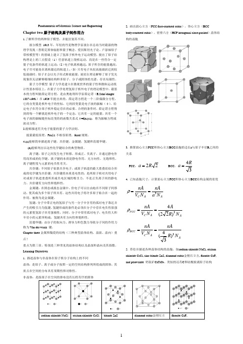
Fundamentals of Materials Science and Engineering Chapter two原子结构及原子间作用力1.了解所学的两种原子模型,并能区别其不同。
玻尔模型1913年,年轻的丹麦物理学家玻尔在总结当时最新的物理学发现(普朗克黑体辐射和量子概念、爱因斯坦光子论、卢瑟福原子带核模型等)的基础上建立了氢原子核外电子运动模型,提出了原子结构理论上的三点假设(1)任意轨道上绕核运动,而是在一些符合一定量子化条件的轨道上运动;(2)电子轨离核越远,原子所含的能量越高,电子尽可能处在离核最近的轨道上;(3)只有电子从较高能级跃迁到较低能级时,原子才会以光子形式释放能量。
玻而尔理论解释了原子发光现象但无法解释精细结构和多原子、分子或固体的光谱,存在局限性。
量子力学模型量子力学是建立在微观世界的量子性和微粒运动统计性基本特征上,在量子力学处理氢原子核外电子的理论模型中,最基本的方程叫做薛定谔方程,是由奥地利科学家薛定谔(E.Schrödinger 1887-1961)在1926年提出来的。
薛定谔方程是一个二阶偏微分方程,它的自变量是核外电子的坐标,它的因变量是电子波的振幅(ψ)。
给定电子在符合原子核外稳定存在的必要、合理的条件时,薛定谔方程得到的每一个解就是核外电子的一个定态,它具有一定的能量,具有一个电子波的振幅随坐标改变的的函数关系式ψ=f(x,y,z),称为振幅方程或波动方程。
2.能够描述有关电子能量的量子力学法则。
能量最低原理,Pauli不相容原理,Hund规则。
4.(a)能够简单描述离子键,共价键,金属键,氢键和范德华键。
(b)能够列出以这些化学键结合的典型物质。
离子键:原子之间发生电子转移,形成正、负离子,并通过静电作用而形成的化学键。
离子键的本质是静电作用,无方向性、无饱和性。
离子键程度与元素的电负性有关。
共价键:不同原子依靠共享电子,或原子轨道的最大重叠而结合形成的化学键为共价键。
工程材料基础 书

工程材料基础书
以下是一些关于工程材料基础的推荐书籍:
1. 《材料力学基础(原理与展开)》(Fundamentals of Materials Mechanics)- William F. Hosford
这本书介绍了工程材料的基本原理和力学行为,涵盖了弹性、塑性、蠕变、疲劳和断裂等方面的内容。
2. 《材料科学与工程》(Materials Science and Engineering: An Introduction)- William D. Callister Jr., David G. Rethwisch
这本书是材料科学与工程的经典教材之一,介绍了工程材料的结构、性质和应用,覆盖了金属、陶瓷、聚合物和复合材料等各类材料。
3. 《材料学导论》(Introduction to Materials Science and Engineering)- William D. Callister Jr., David G. Rethwisch
这本教材提供了关于工程材料科学与工程的基础知识,涵盖材料结构、晶体缺陷、相变、力学行为等方面内容。
4. 《材料科学工程导论》(Introduction to Materials Science for Engineers)- James F. Shackelford
这本书针对工程师介绍了材料科学的关键原理和应用,包括材料结构与性能、材料选择和设计等方面。
这些书籍都是在工程材料基础领域具有良好声誉的教材,适用于大学生、研究生以及从事相关学科研究或工程实践的人员。
值得注意的是,根据个人需求和背景,选择适合自己的教材和参考资料可能会更加有针对性。
材料学有关书籍
材料学有关书籍材料学是一门研究材料的性质、结构、制备、性能、应用以及在各个领域中的发展与应用的学科。
对材料学的学习和研究不仅是工科学生和研究人员必备的背景知识,也对从事材料相关行业和研究的人员来说是非常重要的。
下面我将介绍一些关于材料学的经典和权威的书籍,这些书籍对于对材料学感兴趣的读者来说是非常有帮助的。
1.《材料科学基础》- William D. Callister这本书是对材料科学和工程的经典教材,深入浅出地介绍了材料的总体性质、组成和结构、热力学以及材料的力学行为等方面的内容。
书中配有大量的图片和例子,帮助读者更好地理解和应用所学知识。
2.《材料科学与工程概论》- William F. Smith, Javad Hashemi这本书是指导学生了解和理解材料科学和工程领域的基本概念、原理和应用的教材。
书中详细介绍了各种材料的性质、制备、处理、性能和应用等方面,并提供了一些实际案例和实验数据,帮助学生进行学习和研究。
3.《材料科学导论》- James F. Shackelford这本书对材料科学的起源、发展和应用进行了全面的介绍。
书中不仅介绍了材料的基本性质和分类,还涵盖了材料的结构、热力学、力学、电磁性能等方面的内容,并提供了一些应用案例和实例,帮助读者更好地理解和应用所学知识。
4.《材料科学与工程:依法施工》- R. Balasubramaniam这本书主要介绍了材料科学与工程领域的基本原理和技术,包括材料的种类、制备方法、性质和应用等方面的内容。
书中结合现实案例和实验数据,讲解了材料的特性和行为,帮助读者深入理解材料科学与工程的相关知识。
5.《材料科学导论》- H. L. Geyer这本书介绍了材料科学与工程的基本概念、原理和应用。
书中讲解了各种材料的结构、性质、制备和处理等方面的内容,并提供了一些实际案例和实验数据,帮助读者更好地理解和应用所学知识。
总之,材料学在现代科学和工程中扮演着非常重要的角色,对各个领域的发展具有极大的影响力。
mit出版的材料科学书籍
mit出版的材料科学书籍MIT出版的材料科学书籍材料科学是一门研究材料的性质、结构、制备和应用的学科,涉及到物理、化学、工程等多个领域。
而MIT出版的材料科学书籍则是这个领域中的重要参考资料,为学者和工程师提供了丰富的知识和实践经验。
本文将按照类别介绍几本值得推荐的MIT出版的材料科学书籍。
1. 金属材料《金属材料的力学性能》是一本由William F. Hosford编写的经典教材,介绍了金属材料的力学性能和变形机制。
该书详细讲解了金属材料的塑性、断裂和疲劳等方面的知识,对于研究金属材料的学者和工程师来说是一本不可或缺的参考书。
2. 半导体材料《半导体材料和器件》是一本由Donald A. Neamen编写的教材,介绍了半导体材料和器件的基本原理和应用。
该书详细讲解了半导体材料的物理性质、制备方法和器件结构等方面的知识,对于研究半导体材料和器件的学者和工程师来说是一本不可或缺的参考书。
3. 高分子材料《高分子材料的结构和性能》是一本由James E. Mark编写的教材,介绍了高分子材料的结构和性能。
该书详细讲解了高分子材料的分子结构、物理性质和化学性质等方面的知识,对于研究高分子材料的学者和工程师来说是一本不可或缺的参考书。
4. 纳米材料《纳米材料的制备和应用》是一本由Gleb Yushin和Yury Gogotsi编写的教材,介绍了纳米材料的制备和应用。
该书详细讲解了纳米材料的制备方法、物理性质和应用领域等方面的知识,对于研究纳米材料的学者和工程师来说是一本不可或缺的参考书。
5. 其他材料除了以上几个类别的材料,MIT出版的材料科学书籍还包括了其他类型的材料,如陶瓷材料、复合材料、玻璃材料等。
其中,《陶瓷材料的制备和性能》是一本由M. John Matthewson编写的教材,介绍了陶瓷材料的制备和性能。
该书详细讲解了陶瓷材料的制备方法、物理性质和化学性质等方面的知识,对于研究陶瓷材料的学者和工程师来说是一本不可或缺的参考书。
国外 材料科学 英文 书籍
国外材料科学英文书籍1. "Materials Science and Engineering: An Introduction" by William D. Callister, Jr. 这本书是材料科学与工程领域的经典教材,涵盖了材料的结构、性能、制备和应用等方面。
2. "Principles of Materials Science and Engineering" by Donald R. Askeland and Pradeep P. Phulé. 本书提供了材料科学的全面概述,包括晶体结构、热力学、相图、材料的力学行为等内容。
3. "Introduction to Materials Science for Engineers" by James F. Shackelford. 这本书是为工程师编写的材料科学入门教材,强调了材料的工程应用和设计。
4. "Materials Science and Technology" by R.W. Cahn and P. Haasen. 该书是材料科学领域的权威著作,涵盖了材料的结构、性能、制备和应用等方面,内容深入且广泛。
5. "Materials Characterization: Introduction to Microscopic and Spectroscopic Methods" by Michael F. Ashby and David R. H. Jones. 这本书介绍了材料表征的各种技术和方法,包括显微镜、光谱学和衍射技术等。
这些书籍都是材料科学领域的经典著作,可以帮助读者深入了解材料的结构、性能、制备和应用等方面的知识。
你可以根据自己的需求和兴趣选择适合的书籍进行阅读。
时代教育·国外高校优秀教材精选
市场价:
贵宾会员价:
机械零件设计
M.F.Spotts,
T.E.Shoup
市场价:
贵宾会员价:
数字电子学教师手册
市场价:
贵宾会员价:
电子技术实验
(美)赫尔曼
市场价:
贵宾会员价:
工程电磁场
数学模型(英文版)
市场价:
贵宾会员价:
量子力学概论
David J.Griffiths
市场价:
贵宾会员价:
常微分方程基础
C.Henry Edwards David E.Penney
市场价:
贵宾会员价:
应用微积分:
市场价:
贵宾会员价:
土木工程概论
(印度)M SPalanichamy
市场价:
贵宾会员价:
基础设计:理论与实践
(美)Donald P.Coduto
市场价:
贵宾会员价:
市场价:
贵宾会员价:
机器与机构设计
Homer D.Eckhardt
市场价:
贵宾会员价:
工程材料科学与设计
James P.Schaffer
市场价:
贵宾会员价:
创造突破性产品--
从产品策略到项目定案的创新
Jonathan Cagan Craig M.Vogel
管理、生命科学及社会科学
S.T.Tan
市场价:
贵宾会员价:
结构理论
S.P.Timoshenko,D.H.Young
市场价:
贵宾会员价:
实分析引论
Manfred Stoll
材科基参考书目
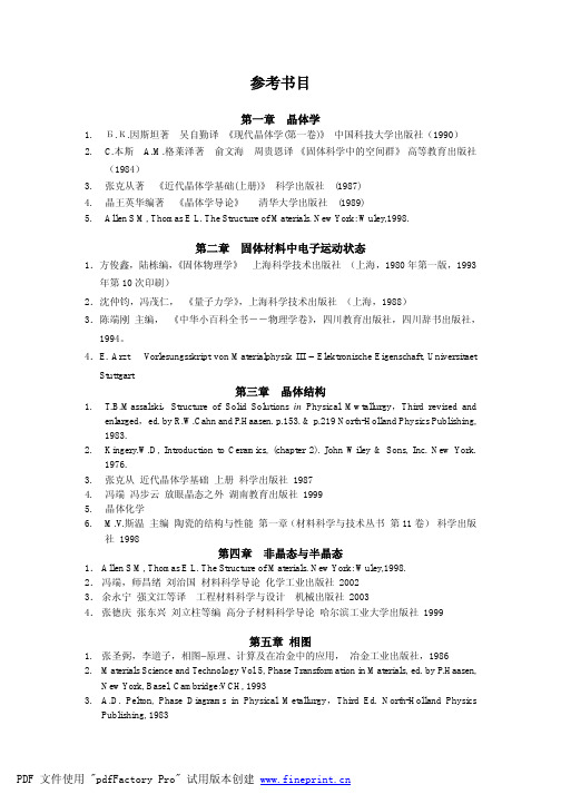
参考书目第一章晶体学1.Б.К.因斯坦著吴自勤译《现代晶体学(第一卷)》中国科技大学出版社(1990)2. C.本斯 A.M.格莱泽著俞文海周贵恩译《固体科学中的空间群》高等教育出版社(1984)3.张克从著《近代晶体学基础(上册)》科学出版社(1987)4.晶王英华编著《晶体学导论》清华大学出版社(1989)5.Allen S M, Thomas E L. The Structure of Materials. New York: Wuley,1998.第二章固体材料中电子运动状态1.方俊鑫,陆栋编,《固体物理学》上海科学技术出版社(上海,1980年第一版,1993年第10次印刷)2.沈仲钧,冯茂仁,《量子力学》,上海科学技术出版社(上海,1988)3.陈端刚主编,《中华小百科全书――物理学卷》,四川教育出版社,四川辞书出版社,1994。
4.E. Arzt V orlesungsskript von Materialphysik III – Elektronische Eigenschaft, Universitaet Stuttgart第三章晶体结构1.T.B.Massalski,Structure of Solid Solutions in Physical Mwtallurgy,Third revised andenlarged,ed. by R.W.Cahn and P.Haasen. p.153. & p.219 North-Holland Physics Publishing, 1983.2.Kingery.W.D, Introduction to Ceramics, (chapter 2). John Wiley & Sons, Inc. New York.1976.3.张克从近代晶体学基础上册科学出版社19874.冯端冯步云放眼晶态之外湖南教育出版社19995.晶体化学6.M.V.斯温主编陶瓷的结构与性能第一章(材料科学与技术丛书第11卷)科学出版社1998第四章非晶态与半晶态1.Allen S M, Thomas E L. The Structure of Materials. New York: Wuley,1998.2.冯端,师昌绪刘治国材料科学导论化学工业出版社20023.余永宁强文江等译工程材料科学与设计机械出版社20034.张德庆张东兴刘立柱等编高分子材料科学导论哈尔滨工业大学出版社1999第五章相图1.张圣弼,李道子,相图−原理、计算及在冶金中的应用,冶金工业出版社,19862.Materials Science and Technology V ol 5, Phase Transformation in Materials, ed. by P.Haasen,New York, Basel, Cambridge:VCH, 19933. A.D. Pelton, Phase Diagrams in Physical Metallurgy,Third Ed. North-Holland PhysicsPublishing, 19834.M. Hansen, K. Anderko, Constitution of Binary Alloys, Mc-Graw-Hill, 1985第六章晶体中的点缺陷和线缺陷1.S.M.Allen, E.L.Thomas, The Structure of Materials. New York: Wuley, 19982.R.W.卡恩, P.哈森, E.J.克雷默, 主编;王佩璇等译, 材料科学与技术丛书, 第1卷, 第7章, 科学出版社, 19983.J.P.Hirth,Dislocation in Physical Metallurgy 3rd edition;North-Holland Physics Publishing,19834.冯顺华, 晶体位错理论基础, 第一卷, 科学出版社, 19885.W.F. Harris, Scientific American. 1977, 237; 666.余永宁, 毛卫民, 材料的结构, 冶金工业出版社, 2001第七章面缺陷和体缺陷1.S.M.Allen, E.L.Thomas. The Structure of Materials. New York: Wuley, 19982.James M. Howe. Interfaces in Materials. Wiley, 19993. F.J.Humphreys and M.Hatherly, Recrystallization and Related Annealing Phenomena,Galliard (Printers) Ltd. 19954.Materials Science and Technology, vol 1,Structure of Solids,ed. by V.Gerold,New York,Basel,Cambridge:VCH. 19935.李恒德,肖纪美主编,材料表面与界面,清华大学出版社,19906.R.E.Smallman, R.J.Bishop, Modern Physical Metallurgy and Materials Engineering, Sixth Ed,Oxford OX2 8DP 1999第八章材料中原子扩散1.J.L.Bocquet, J.Brebec and Y.Limoge Diffusion in Metals and Alloys, in Physical Metallurgy,Third Ed. North-Holland Physics Publishing, 19832.J. S. Kirkaldy, Diffusion in the Condensed State, The Universities Press (Belfast) Ltd. 19873.李长海,余永宁译, 金属和合金中的相变, 冶金工业出版社,19884.J. Crack, The Mathematics of Diffusion, Second Edition, Oxford University Press, 19755.Materials Science and Technology, V ol 5, Phase Transformation in Materials, ed. by P.Haasen,New York, Basel, Cambridge:VCH. 19936.W.D Kingery. Introduction to Ceramics, John Wiley & Sons, Inc. New York. 1976第九章材料的形变1. 哈宽富,金属力学性质的微观理论,科学出版社,19832. Richard W. Hertzberg, Deformation and Fracture Mechanics of Engineering Materials,JohnWiley & sons. 19833. B.Bay, N.Hansen, Acta Metall.Mater., 40, 1992, 205∼2194. F.J.Humphrey & M.Hatherly, Recrystallization and Related Annealing Phenomena,Pergamon,19955. R.W.卡恩,P.哈森,E.J.克雷默主编,颜鸣皋等译,材料科学与技术丛书,第6卷第1、2、3章,科学出版社,19986. 冯端,师昌绪,刘治国主编,材料科学导论,化学工业出版社,20027. R.W.Cahn and P.Haasen. Physical Metallurgy. Fourth, revised and enhanced edition. Elsevier Science BV. 1996, V ol.3, Chapter 32: A metallurgist’s guide to polymers. By A.H.Windel8.赵品,谢辅洲,孙文山,材料科学基础,哈尔滨工业大学出版社,19999. 刘智恩, 材料科学基础,西北工业大学出版社,200010. J.W.Christian and S.Mahajan. Deformation Twinning. Progress in materials science. 1995.V ol.39. 1-15711.余永宁,强文江等译,工程材料科学与设计,机械工业出版社,200312. J.Hirsch, K.Lücke and M.Hatherly. Mechanism of deformation and development of rollingtextures in polycrystalline F.C.C. metals---III. The influence of slip inhomogeneities and twinning. Acta metall. 36, 1988, No.11. 2905-2927第十章相变的基本原理1. D.A.Port, K.E.Eastering. Phase Transformations in metals and alloys. 19922.冯端,师昌绪,刘治国主编,材料科学导论,化学工业出版社,20023. R. W. Cahn,Physical Metallurgy,4rd,revised and enlarged ED.,ed. by R.W.Cahn andP.Haasen, Elsever Publishing, 19964. G.Gottstein. Physical foundations of materials science. Springer-V erlag, 2004第十一章凝固1.弗莱明斯著,关玉龙等译,凝固过程,冶金工业出版社, 19812.戴维斯著,舒震等译,凝固与铸造,机械工业出版社, 19813. D.A.Port, K.E.Eastering. Phase Transformations in metals and alloys. 19924.H.Boloni in Physical Metallury,Ed. by R.W.Cahn and P.Haasen, North-Holland Pub. 3rdedition, 477-579, 19835.I. Minkoff, Solidfication and Cast Structures, John Wiley and Sons Ltd., 19866.冯端,师昌绪,刘治国主编,材料科学导论,化学工业出版社,2002第十二章固态转变1. R. W. Cahn,Physical Metallurgy,4rd,revised and enlarged ED.,ed. by R.W.Cahn and P.Haasen,Elsever Publishing, 19962. Hsun Hu(胡郇),物理冶金进展评论,中国金属学会编译组译,冶金工业出版社,1985 ,pp.151-1873. R.K.Ray, J.J.Jonas and R.E.Hook. Cold rolling and annealing textures in low carbon and extralow carbon steels. International Materials Review. 1994. V ol.39. No.4. 129-1724. G.Gottstein. Rekristallisation metallischer Werkstoffe. Deutsche Gesellschaft fuer MetallkundeE.V. 19845. J.Hjelen, R.rsund and E.Nes. On the origin of recrystallization textures in Aluminium. Actametal. 39, 1991. No.7. 1377-14046. A.Berger, P.-J.Wilbrandt, F.Ernst, U.Klement and P.Haasen. On the generation of neworientations during recrystallization: Recent results on the recrystallization of tensile-deformed fcc single crystals. Progress in materials science. 32, 1988. 1-957.余永宁. 金属学原理. 冶金工业出版社,20008. D.A.Port, K.E.Eastering. Phase Transformations in metals and alloys. 19929.G.Gottstein. Physical foundations of materials science. 2004, Springer-V erlag 10. 徐恒均. 材料科学基础. 北京工业大学出版社,2001。
工程材料科学与设计 答案
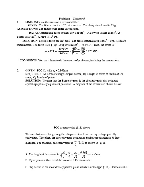
Problems - Chapter 5 1. FIND: Calculate the stress on a tensioned fiber.GIVEN: The fiber diameter is 25 micrometers. The elongational load is 25 g. ASSUMPTIONS: The engineering stress is requested.DATA: Acceleration due to gravity is 9.8 m/sec 2. A Newton is a kg-m/sec 2. A Pascal is a N/m 2. A MPa is 106 Pa.SOLUTION: Stress is force per unit area. The cross-sectional area is πR 2 = 1963.5 square micrometers. The force is 25 g (kg/1000g)(9.8 m/sec 2) = 0.245 N. Thus, the stress isσ = F/A =02451960100125262..N umum m MPa⨯☞☟☝✋ ☺=COMMENTS: You must learn to do these sorts of problems, including the conversions. 2. GIVEN: FCC Cu with a o = 0.362nmREQUIRED: A) Lowest energy Burgers vector, B) Length in terms of radius of Cu atom, C) Family of planesSOLUTION: We note that the Burgers vector is the shortest vector that connects crystallographically equivalent positions. A diagram of the structure is shown below:FCC structure with (111) shownWe note that atoms lying along face diagonals touch and are crystallographically equivalent. Therefore, the shortest vector connecting equivalent positions is ½ face diagonal. For example,one such vector is10]1[ 2a o as shown in (111).A. The length of this vector is0.256nm = 20.362= 2a= 4a+ 4a o 2o 2oB. By inspection, the size of the vector is 2 Cu atom radii.C. Slip occurs in the most densely packed plane which is of the type {111}. These are thesmoothest planes and contain the smallest Burgers vector. This means that the dislocations move easily and the energy is low.3. GIVEN:∣b∣ = 0.288nm in AgREQUIRED: Find lattice parameterSOLUTION: Recall the Ag is FCC. For FCC structures the Burgers vector is ½ a facediagonal as shown. We see that4. A. FCC structureThe (111) plane is shown in a unit cell with all atoms shown. Atoms touch along face diagonals. The (111) plane is the most closely packed, and the vectors shown connect equivalent atomic position. Thus 10]1[ 21= b etc. Then in general >110< 2a= bB. For NaC1We see that the shortest vector connecting equivalent positions is 10]1[ 2aas shown. Thisdirection lies in both the {100} and {110} planes and both are possible slip planes. However {110} are the planes most frequently observed as the slip planes. This is because repulsive interionic forces are minimized on these planes during dislocation motion. Thus we expect 1/2<110> Burgers vectors and {110} slip planes.5.GIVEN:Mo crystal0.272nm = ba o = 0.314nmREQUIRED: Determine the crystal structure.If Mo were FCC, then 0.222nm = 20.314= b __but |b| = 0.272 ⇒ Mo is not FCC.Assuming Mo is BCC, then 0.272nm.= 0.314 X 23 = b __Thus the Burgers vector isconsistent with Mo being BCC.6.FIND: Is the fracture surface in ionic solids rough or smooth?SOLUTION: Cleavages surfaces of ionic materials are generally smooth. Once a crack is started, it easily propagates in a straight line in a specific crystallographic direction on a specificcrystallographic plane. Ceramic fracture surfaces are rough when failure proceeds through the noncrystalline boundaries between small crystals.7. GIVEN: BCC Cr with |b| = 0.25nmREQUIRED: Find lattice parameter aASSUME: >111< 2a= b for BCC structureSOLUTION:2a 3= 4a+ 4a+ 4a= b 222__from the formula for the magnitude of a vector:8. GIVEN: Normal stress of 123 MPa applied to BCC Fe in [110] directionREQUIRED: Resolved shear in [101] on (010)SOLUTION: Recall that the resolved shear stress is given by:τ = σ cos θ cos φ (1)where θ = angle between slip direction and tensile axis; φ = angle between normal to slip plane and tensile axisThus MPa 43.5 = 2121 123 = ⎪⎭⎫⎝⎛⎪⎭⎫ ⎝⎛τ9. GIVEN: Stress in [123] direction of BCC crystalREQUIRED: Find the stress needed to promote slip if τcR = 800 psi. The slip plane is (11_0) and slip direction is [111]. SOLUTION: Recall τ = σ cos θ cos φ (1)θ = [123] [111][123] ⋅ [111] = ∣[123]∣ ∣[111]∣cos θφ = [123] [11_0][123] ⋅ [11_0] = ∣[123]∣ ∣[11_0]∣cos φ10.Burgers vectors lie in the closest packed directions since the distance between equivalentcrystallographic positions is shortest in the close-packed directions. This means that the energy associated with the dislocation will be minimum for such dislocations since the energy is proportional to the square of the Burgers vector.11. Close packed planes are slip planes since these are the smoothest planes (on an atomic level) and would then be expected to have the lowest critical resolved shear stress.12.GIVEN: Dislocation lies on (11_1) parallel to intersection of (11_1) and (111) with Burgers vector parallel to [1_1_0]. Structure is FCC.REQUIRED: A) Burgers vector of dislocation and, B) Character of dislocation.SOLUTION: A) Since the structure is FCC, the Burgers vector is parallel to <110> and has magnitude. 2a For a Burgers vector parallel to [1_1_0] the scalar multiplier must be a/2. Thus b _ = a/2 [1_1_0]. B) We must determine the line direction of the dislocation. From the diagramwe see that the BV and line direction are at 60o which means the dislocation is mixed.13. GIVEN: Dislocation reaction below:REQUIRED: Show it is vectorially correct and energetically proper. SOLUTION: [100] a =] 111[ 2a+[111] 2aThe sum of the x, y & z components on the LHS must be equal to the corresponding component on the right hand side.x component (LHS) = x component (RHS)y component (LHS) = y component (RHS)z component (LHS) = z component (RHS)Energy: The reaction is energetically favorable if | b 1 | 2 + | b 2 | 2 > | b 3| 3Thus the reaction is favorable since a > a 43+ a 4322214. GIVEN: Dislocation in FCCParallel to [1_01] i.e. t_ = [1_01]REQUIRED: Character and slip planeSOLUTION: Character is found by angle between b_ and t_. Note b_ t_∙ = -1 + 0 + 1 = 0. Thus b__t_. Since b__t_the dislocation is pure edge.To find the slip plane we note that the cross produce of t_ & b_gives a vector that is normal to the plane in which t_ & b_lie. This vector so formed has the same indices as the plane since we have a fundamentally cubic structure.We see from the diagram that these vectors lie on (010).Thus, we have the plane (01_0) which is the same as the (010) plane. This does not move by glide since planes of the kind {100} are not slip planes for the FCC structure.15.FCC metals are more ductile than BCC or HCP because: 1) there is no easy mechanism for nucleation of microcracks in FCC as there is for BCC and HCP; 2) the stresses for plastic deformation are lower in FCC due to the (generally) smoother planes. This means that the microcracks that form in BCC & HCP will have high stresses tending to make them propagate. 16.For a simple cubic system, the lowest energy Burgers vectors are of the type <001> since this is the shortest distance connecting equivalent atomic positions. This means that the energy is lowest since the strain energy is proportional to the square of the Burgers vector. 17.GIVEN:At. wt. 0 = 16At. wt. Mg = 24.32 Same structure as NaCl ρ = 3.65 g/cm 3REQUIRED: Find length of Burgers Vector in MgOSOLUTION: The structure of MgO is shown schematically below along with the shortestBurgers vector. To solve the problem we first note that we require the lattice parameter a o . We can take a sub-section of the unit cell (cross-hatched cube) whose edge is 2a o unitslong.We can calculate the total mass of this cube and the volume and calculate the density. Since the mass is known and the density is known, the volume may be calculated from which a o may beextracted.and ½ Mg ++ ions in our cube. Thus a10 x 3.35 x 8= 8/ a 10 x 2.02) + (1.33= 3.653o-233o-2318.GIVEN: Critical resolved shear stress (0.34MPa), slip system (111)[1_10], and tensile axis [101]REQUIRED: Applied stress at which crystal begins to deform and crystal structure. SOLUTION: (A)The situation is shown belowτcrss = σ cos θ ⋅ cos φθ = angle between tensile axis and slip directionθ = angle between tensile axis and normal to slip planeφ = [111] [101] θ = [101] [1_01][111] ⋅ [101] = ∣[111]∣ ∣[101]∣cos φ [101] ⋅ [110] = ∣[101]∣ ∣[110]∣cos θ(B): To have a {111}<110> slip system, the material must have an FCC structure.19. GIVEN:τcrss = 55.2 MPa, (111)[1_01] slip system, [112] tensile axisREQUIRED: Find the highest normal stress that can be applied before dislocation motion in the [10 1_] direction.SOLUTION: The situation is shown below. Essentially the problem reduces to finding the value of the tensile stress when the critical resolved shear is reached.τcrss = σ cosθ⋅ cosφθ = [112] [1_01] φ = [112] {111}B. Would have exactly the same stress for a BCC metal (φ & θ would be interchanged).20. GIVEN:σ at yield = 3.5 MPa; (111) [11_0] slip system [11_1] tensile axisREQUIRED: Compute τcrssSOLUTION:τcrss = σcosθcosφθ = [11_1] [11_0] φ = [11_1] [111]21. Item Edge ScrewLinear defect? Yes YesElastic Distortion? Yes YesGlide? Yes YesClimb? Yes NoCross-slip? No YesBurgers Vector (BV) ⊥ to line // to lineUnique slip plane? Yes NoOffset // to BV // to BVMotion // to BV ⊥ to BV22. GIVEN: BCC metal with τcrss = 7MPa [001] tensile axis.REQUIRED: (a) Slip system that will be activated and (b) normal stress for plasticdeformation.SOLUTION: Recall that for BCC metals the usual slip system is <111> {110}. Deformation occurs on the plane and direction for which cos θ⋅cos φ is a maximum since this will have the maximum resolved shear stress. The situation is shown below.(Note that the slip directions are shown shortened in this view)Possible slip systems are listed below:sketch (also [11_1] on (011)) (also [1_11] on (01_1)) (also [1_1_1] on (101)) similar to planes shown in sketch. Also [111] on (1_01)We see by inspection that the resolved shear due to a tensile force in [001] will all be the same. The resolved shear on all other {110}<111> systems is zero.B. To compute the normal stress at the onset of plastic deformation we will consider (011) [1_1_1]τcrss = σcos θcos φ = 7θ = [001] [1_1_1]; cos φ = [001] [011]Note if we considered (101) [1_1_1] we would haveand we would obtain exactly the same answer.23. GIVEN: Yielding occurs at normal stress of σ = 170 MPa in [100] direction. Dislocationmoves on (101) in [111_] direction.REQUIRED:τcrss and crystal structuresSOLUTION: Assume an edge dislocation. τcrss = σcos⋅cosφθ = [100] [111_] φ = [100] [101]The - sign means that the slip direction is opposite to the motion of the dislocation. Essentially, we have a negative edge dislocation on (101) as shown below:The edge dislocation moves in [111_] direction but the offset is in [1_1_1] direction.The slip plane and slip direction are representative of BCC structures.24. GIVEN: (1_10)[111] slip system. [123] tensile axisτcrss = 800 psi for BCC crystal τcrss = 80 psi for FCC crystal withσFCC = 457 psi [123] tensile axis and (111)[11_0] system.REQUIRED: Normal stress at yield for BCC metalSOLUTION: The simplest way to solve this problem is to note cos θ⋅cos φ is the same for the BCC and FCC crystal with the meaning of φ and θ interchanged. Let M = cos θ⋅cos φ. (1) (2)(3)25.Here crystallographically equivalent positions join ions at cube corners (b v = a o ), face diagonals )a 2 = b (o v , cube diagonals )a 3 = b (o vThe most densely packed plane is the (110) in which we haveThe shortest vector that will reproduce all elements of the structure is a o . Thus b = a<100> COMMENT: We note that this is not sufficient for general deformation (e.g. a tensile axis ofthe type <100> produces zero shear on the 1<100> Burgers vectors. We expect then a<110> Burgers vectors as well.26. GIVEN:σ = 1.7 MPa [100] tensile axis (111)[101] slip systemsREQUIRED:τcrss, and crystal structure. Also find flaw in problem statement.SOLUTION: Since the slip system is of the type {111}<110> the structure is FCC. Theproblem is misstated since the Burgers vector must lie on the slip plane and [101] does not lieon (111). The slip direction would more appropriately be [101_]. Thus the slip system is(111)[101_] as shown below.27.⊥ = edge dislocation x = start of Burgers circuitb = Burgers vector y = end of Burgers circuit28. FIND: Show energy/area = force/length, that is, surface energy is surface tension in liquids.DATA: The units of energy are J = W/s or N-m. The units of force are N.SOLUTION: Energy/area = J/m2 =N-m/m2 = N/m = force/length29. GIVEN: Two grain sizes, 10μm and 40μmREQUIRED: A) ASTM GS# for both processes, B) Grain boundary area.SOLUTION: Assume that the grains are in the form of cubes for ease of calculation. TheASTM GS# is defined through the equation: n = 2N-1 where n = # grains/in2 at 100X.N=ASTM GS#To solve the problem we first convert the grain size to in. where D = length of cube edge in μm.At 100X linear magnification, the sides of the smaller grains will be:The area of each grain at 100X will beSimilarly the area of the 40μm grains at 100X isFor the 10μm dia grain, the # of grains per in 2 (at box) is645.16 = 10x 1.5501= n3-100X10μgrains/in 2at 100X Similarly 40.31 = 10x 24.811= n 3-100X 40μgrains/in 2at 100X For the 10μm grain size:B. In computing the total g.s. area we will assume 1 in 3 of materials. Since there are 6 facescube and the area of each face is shared by 2 cubes, each cube has an area of 3x Area of face. G.B. Area =d / 3 = d 3 x d 123⎥⎦⎤⎢⎣⎡GB Area (10μ gs) = 3/3.937 x 10-4 = 7620in 2/in 3 GB Area (40μ gs) = 3/15.75 x 10-4 = 1905in 2/in 330.GIVEN:σys = 200MPa at GS#4 = 300MPa at GS#6REQUIRED: σys at GS#9SOLUTION: Recall σys = σo + kd -1/2(1)for low carbon steel.If d = grain size (assume cubes) load = grain diameter at 100X(2)(3)16.82 = d11/24For ASTM GS# 4:For ASTM GS#6:23.78 = d11/24(5) Substituting (4) and (5) into (1) we have200 - σo + k(16.82) (6) 300 = σo + k(23.78) (7)Subtracting (6) from (7):100 = k(23.78 - 16.82)∴k = 14.37Substituting this value of κ into (6) yields 200 = σo + 14.37 x 16.82σo = -41.70 (this is not physically realistic since σo relates to the lattice friction stress which should not be negative)For ASTM GS#9Thus σys = σo + 14.37 x 40 = 41.70 + 574 = 533MPa31.GIVEN: ∣b ∣ = 0.25μm for BCC metal tilt boundary has angular difference of 2.5o REQUIRED: Dislocation density in tilt boundary wall SOLUTION: The physical situation is shown below:If b = Burgers vector, D = spacing between edge dislocation# of dislocations in boundary for a 1cm high boundary isD1(where D is in cm)32.33.FIND: Show D = b / θ.GIVEN: b is the magnitude of the Burger's vector; D is the spacing between dislocations, and θ is the tilt angle.SKETCH: See Fig. 5.3-4.SOLUTION: We can see the geometry more clearly using the following sketch:bFrom the Figure we can immediately write that tan/θ22=b D . Since the tan of a small angle is the angle itself:θ22=b D /, so that D = b / θ, as is written in the margin.34. FIND: How can you detect a cluster of voids or a cluster of precipitates in a material?SOLUTION: This can be a difficult challenge indeed. If the total void volume is large, then the density of the sample will be lower than that of dense material. The same is true for clusters ofprecipitate; however, usually the density difference between host and precipitate is not as greatas between host and air, so the technique does not work as well. Another possible technique is microscopy. Samples can be prepared for microscopy, perhaps by polishing and etching andthe defects observed using optical or electron microscopy. X-ray diffraction can also be used. With a random spacing of void or precipitate there is then an average spacing. SometimesBragg's law can be used to calculate the spacing if an intensity maximum is observed. Note that the angle of the maximum will be very small.COMMENTS: There are many other potential techniques that can potentially be used. Theyall rely on some property difference - magnetic, electrical, optical, or whatever.35. FIND: How can you ascertain whether a material contains both crystalline and noncrystallineregions?GIVEN: Recall that the density (and other properties) of crystalline material is greater than that of noncrystalline material of the same compositionSOLUTION: There are three methods in common usage to establish crystallinity polymers.These methods apply to all materials.1. Density. Measure the density of your sample and compare it to the density of noncrystallineand crystalline samples of the same composition.2. Differential Scanning Calorimetry. Heat your sample in a calorimeter. Samples that arecrystalline will absorb heat at the melting temperature and show a "melting endotherm". Somenoncrystalline samples (such as amorphous metals) will crystallize in the calorimeter and show a huge release of heat prior to melting. This is a "crystallization exotherm".3. X-ray diffraction. Crystalline materials show well-defined peaks.COMMENTS: Knowing whether a material is crystalline or noncrystalline is a commonchallenge to polymers scientists. We often need to quantify the fraction or percent crystallinity.Can you suggest a method for each of the 3 techniques outlined?36. FIND: State examples of materials' applications that require the material to behave in a purelyelastic manner.SOLUTION: There are many such possible examples. Since plastic deformation isnonrecoverable deformation, any application that requires repeated stressing and dimensional stability is a good example. Here are some examples:1. Springs in automobiles - leaf and coil springs2. A diving board3. Trusses in a bridge4. The walls in a building5. A bicycle frame6. Piano wire7. Airplane wings37. As the dislocation density ↑, there are more dislocation/dislocation interactions and the strengthgoes up. At the same time, the degree of “damage” also increases and the ductility decreases.38. If the point defect concentration ↑, the strength will go up as well. This is because the defectsmay migrate to edge dislocations where they cause jogs on the dislocations. A joggeddislocation is much harder to move and may itself require the generation of point defects tomove. In addition the point defects may collapse to form dislocation loops which also impede the motion of other dislocations making the materials stronger. If the defects are interstitials,they may migrate to areas around the dislocations in which the system energy is reduced. For the dislocation to move away from the interstitial an increase in the system energy is requiredwhich means the stress to move the dislocation must increase. If the point defect is asubstitutional atom, similar considerations apply. However, the magnitude of the energyreduction is less because of the less severe distortion. Thus the strength increase is not as high as for intersitital.39. As d↓σys↑ since this means the path over which a dislocation moves ↓. This means that thestress will have to increase to either nucleate or unlock dislocations in adjacent grains. Therelationship quantifying this behavior is the Hall-Petch equation: σys = σo + kd-1/240. The strength may increase as a result of:1. decreasing grain size - should not be too (see previous questions) temperature dependent.2. Adding impurities (e.g. C in Fe). The impurities “lock” the dislocation by associating withthe dislocation to lower the system energy. This will be very temperature dependent for dilute concentrations of impurities as the impurities will diffuse away at high temperatures.3. Adding precipitates - blocks the motion of dislocations through either having a differentcrystal structure or a large strain field. Since the precipitates are usually large compared to the atomistic dimension, strong temperature dependence is not expected.4. Cold work - increase quantity of dislocations.41. GIVEN: = 1012/cm 2 for low C steelREQUIRED: concentration of C atoms (at %) to lock all dislocationsSOLUTION: Recalling the At. weight of Fe is 55.85 and the density is about 7.8 gm/cm 3 we may write10 x 6.02 55.857.8 = N 23Fc(assume 1C atom for every Fe atom along dislocations)42. FIND: Why can you not bend the bar of tin?GIVEN: The bar has been well annealed, so the initial dislocation density is low. You are required to re-bend the bar after cold working.SOLUTION: The deformation has increased the dislocation density and the bar now requires much more stress, or force, to deform it. You are not necessarily a weakling, but you have been taken. Re-anneal the bar and bend it back or use brute force.COMMENTS: It is often difficult to bend a metal back to its original shape and this is just one of many possible reasons that depend on the metal and its thermo-mechanical。
- 1、下载文档前请自行甄别文档内容的完整性,平台不提供额外的编辑、内容补充、找答案等附加服务。
- 2、"仅部分预览"的文档,不可在线预览部分如存在完整性等问题,可反馈申请退款(可完整预览的文档不适用该条件!)。
- 3、如文档侵犯您的权益,请联系客服反馈,我们会尽快为您处理(人工客服工作时间:9:00-18:30)。
7
《材料科学与工程导论》讲义
系统中的固体 (1)机械混合物, 有几种物质就有几相 (2)生成化合物,固态物质间每生成一个新的化合物,则形成一种新
的固态物质,即产生一个新相。 (3)形成固溶体 (4)同质多晶现象
8
《材料科学与工程导论》讲义
3.独立组元 系统中每一个能够单独分离出来并能独立存在的化学纯物质称为组元。
©2003 Brooks/Cole, a division of Thomson Learning, Inc. Thomson Learning™ is a trademark used herein under license.
图 7.3 镁的一元相图 Schematic unary phase diagram for magnesium, showing the melting and boiling temperatures at one atmosphere pressure.
相平衡与相图
《工程材料科学与设计》 (James P. Schaffer等著)
余永宁等翻译 机械工业出版社
Wisdom in the mind is better than money in the hand.
Nothing is impossible for a willing heart.
2
《材料科学与工程导论》讲义
2.相(phase) 系统中具有相同物理与化学性质的完全均匀部分的总和称为相。 (1)相与相之间有界面; (2)可用机械的方法将它们分开,越过界面时性质发生突变; (3)系统中存在的相可以是稳定的、亚稳的或不稳定的。 (4)系统在某一热力学条件下,只有当能量具有最小值的相才是最稳定的。系 统的热力学条件改变时,自由能会发生变化,相的结构也相应发生变化。
影响系统平衡状态的外界因素包括:温度、压力、电场、磁场、重力 场等。外界影响因素的数目称为影响因数数。
在一般情况下,只考虑温度和压力对系统平衡状态的影响。
10
《材料科学与工程导论》讲义
二、相图(phase diagram)
相图:描述物质的状态与温度、压力及成分之间关系的图解。
根据相图可确定不同成分的材料在不同温度下组成相的种类、各相的 相对量、成分及温度变化时可能发生的变化。仅在热力学平衡条件下成立, 不能确定结构、分布状态和具体形貌。
9
《材料科学与工程导论》讲义
4.自由度
在一定范围内,可以任意改变而不引起旧相消失或者新相产生的独立变 量称为自由度。
一个系统中有几个独立变量就有几个自由度。
对于给定的相平衡系统,在保持系统中相的数目和相的状态下不发生变 化的条件下,并不是温度、压力、组分的浓度等所有的变量都可以任意改变。
5.外界影响因素
eg 在盐水中,NaCl和水都是物种,而Na+、Cl-、H+、OH-等离子就不是物种, 因为它们不能独立存在。
只有特定条件下,独立组元和组元的含义才是相同的。若系统中不发生 化学反应,则:
独立组元数=物种数 eg 砂糖和砂子
盐和水
如果一个系统中,同一相内存在一定的浓度关系,则独立组元数为 独立组元数=物质数-独立的化学平衡关系式数
14
《材料科学与工程导论》讲义
在一个相图中可能存在多个三相点
图7.4 铁的平衡温度—压力图
15
《材料科学与工程导论》讲义
7.3 二元相图
溶解度 :一种 物质溶解在另外 一种物质中而且 不生成第二相, 溶解的量就称为 溶解度。
©2003 Brooks/Cole, a division of Thomson Learning, Inc. Thomson Learning™ is a trademark used herein under license.
聚合物科学中相图的使用受到限制: (1)达到平衡的速度非常慢。大多数溶化过程聚合物永远达不到平衡 (2)聚合物含有很多分子,每个分子的相对分子量都不同 (3)除非聚合物的化学结构非常相似,否则它们通常是不相容的。
11
《材料科学与工程导论》讲义
7.2 单元系相图
图7.2 水的相图
12
《材料科学与工程导论》讲义
6
《材料科学与工程导论》讲义
eg 水和水蒸气共存,组成虽同为H2O,但物理性质不同,故为两个不同的相。 乙醇和水混合形成的溶液 整个系统只是一个液相 油和水混合 二相系统 空气(O2,N2,CO2) 一个相
系统中液体,纯液体是一相;混合液体完全互溶,即为一相,分层则不止一相
©2003 Brooks/Cole, a division of Thomson Learning, Inc. Thomson Learning™ is a trademark used herein under license.
图 7.1 相与溶解度的示意图
Illustration of phases and solubility: (a) The three forms of water – gas, liquid, and solid – are each a phase. (b) Water and alcohol have unlimited solubility. (c) Salt and water have limited solubility. (d) Oil and water have virtually no solubility.
13
《材料科学与工程导论》讲义
相律 Gibbs phase rule
1876年美国 W.Gibbs从热力学推导出来
(1)表达式:f=c-p+2; f:自由度; c:独立组元数; p:相数 压力一定时,f=c-p+1。
(2)应用 可确定系统中可能存在的最多平衡相数。 如单元系2个,二元系3个。解释纯金属 与二元合金的结晶差别。纯金属结晶恒 温进行,二元合金变温进行。
7.0 前言
Freeze-dried coffee (冻干咖啡) 3
《材料科学与工程导论》讲义
How ice skater move so easily on ice? 4
《材料科学与工程导论》讲义
世界上的山到底能有多高?
5
《材料科学与工程导论》讲义
7.1 相与相图
一、相平衡的基本概念 1.系统 选择的研究对象称为系统。 系统以外的一切物质都称为环境。ห้องสมุดไป่ตู้