海德牌小型扫路车各地用户使用照片
农机资料维美德T171h拖拉机介绍幻灯片PPT

自动行走控制
由一个独立的“N”开关控制。 这种自动行走控制功能,对于地头转弯,及需要 频繁停车的作业,如:拖拉机带前装载机或打捆 机作业,非常方便。
1. 拖拉机停车 行驶速度低于10公里/小时时, 踏下刹车踏板。 或 发动机转速低于1100转/分时, 松开油门。
2. 拖拉机继续行走 当下列条件同时满足时,拖拉机继续行走:
结合行驶方向 松开刹车踏板 发动机转速高于1100转/分
动力制动系统(T151eh-T191h)
油浸式制动摩片位于差速器和左右 最终传动之间。制动由制动踏板通过 液压油控制。踏板 → 制动液(油) → 摩片。没有单独的制动油路。
利用传动/液压油进行制动,制动力 更大。 系统装有压力蓄能器,因此即使发 动机熄火,制动仍然起作用。
A 正常使用时的额定功率
B 正常使用时的最大功率
C 运输功率提升模式下的额定功率
D 运输功率提升模式下的最大功率
T171h的发动机曲线
传动系统的组成
缓冲盘
变速箱:有三个速度区段, 4个速度挡。共12个前进挡,
12个后退挡。
微调负载换挡机构 (DPS),比例控制
提升臂
动力输出轴
传动轴
负载换向部分:两组 湿式多片离合器(即:
注意:当需要对拖拉机进行精确控制 时,建议使用离合器踏板。
负载换向的控制
由离合器踏板、手动离合器、负载换向 操纵杆和计算机多重控制,可靠性高。 负载换向操纵杆同时也是手刹车。 只要轻轻地移动负载换向操纵杆,即可 实现平稳、快捷地换向。无须停车,无须 使用离合器踏板。 可以为前进/后退编程设置不同的微调挡 。设置后,在显示屏上会有相应的显示( 如:地头转弯或带前装载机时,可以较低 的发动机转速获得较大的行驶速度)。
扫路车使用说明书-通用

扫路车使用说明书目次序言 (02)特别提示 (03)1车辆识别 (04)11产品标牌位置 (04)12VIN号码位置 (04)2概述 (04)3技术参数 (04)31扫路车外形图 (04)32整车性能与技术参数 (04)33主要部件型式与参数 (05)34扫路车加油(脂)加水部位 (06)4结构简介与使用调整 (06)41副发动机、风机传动系统 (06)42吸嘴装置 (07)43清扫装置 (08)44液压系统 (10)45电控与仪表系统 (11)46洒水系统 (12)47垃圾箱………………………………………………………………………..(13)48副车架 (14)5使用与操作 (14)51操作装置与仪表 (14)52新车的使用 (18)53扫路车操作规程 (19)54扫路车的操作 (19)6维护与保养 (21)61例行保养 (21)62一级保养 (21)63二级保养 (22)64三级保养 (22)65润滑 (22)7故障分析与排除 (23)8安全防护 (25)9主要配件包修期限 (26)序言欢迎您使用本公司系列扫路车。
为使您拥有的扫路车发挥最佳效能,是我们的共同目标,但一定程度上取决于您对扫路车操作的熟悉程度和保养得是否仔细、全面。
本说明书为您提供了扫路车的主要技术性能、操作使用注意事项、结构、调整、保养和故障排除等说明,我们诚恳地希望您在使用扫路车前能仔细阅读本说明书和配套的汽车底盘说明书、副发动机说明书,并按所介绍的方法操作和保养,以保证安全作业并延长车辆使用寿命。
本公司以用户第一为服务宗旨,提供优良的售后服务,为用户进行技术培训,提供零配件及维修服务,解除用户的后顾之忧。
我们衷心欢迎用户将服务要求、使用信息和改进建议函告我公司,以便进一步提高产品质量,更好地为用户服务。
本使用说明书,提供了产品的主要技术参数,主要部件结构与调整,以及操作与保养方面的知识。
本说明书的内容在出版时是正确的,但我公司产品总是不断改进创新力求做的更好,产品改进后,恕不另行通知,敬请使用中注意。
CHD5021TSL扫路机

CHD5021TSL扫路机产品性能特点描述海德牌CHD5021TSL扫路机是一款专用底盘整体结构扫吸式小型扫路机。
该扫路机技术性能领先于同类产品且外形美观,操作灵活。
CHD5021TSL扫路机由一台久保田柴油发动机输出整机作业动力,全部作业均由液压传动完成。
扫路机两扫刷布置于驾驶室前方两侧,吸口布置于驾驶室下面中间,清扫作业视野良好操作便捷。
扫路机抽吸系统为气流循环反吹结构,部分气流经过袋式过滤器过滤后排出,清扫作业时不会产生出风扬尘二次污染,获有国家专利的吸口反吹结构使吸口抽吸效率提高。
扫路机安装有获有国家专利的排气过滤装置,可以无水干式清扫、干湿两用作业。
CHD5021TSL扫路机已获得9项国家专利:1、一种扫路机铰接转向装置,专利号:ZL200920252445.3;2、一种发动机散热风扇和空调压缩机传动装置,专利号:ZL200920252439.8;3、一种扫路机排气过滤装置,专利号:ZL200920252441.5;4、一种扫路车反吹式吸口,专利号:ZL200920252444.9;5、一种扫路车吸口和扫刷提升悬挂装置,专利号:ZL200920252443.4;6、一种盘式扫刷,专利号:200920252442.X;7、一种发动机飞轮端动力传动装置,专利号:ZL200920252438.3;8、一种驾驶室顶置安装的空调蒸发器总成,专利号:ZL200920252440.0;9、一种使用标准垃圾桶装载垃圾扫路机垃圾装载装置,专利号:ZL200920252446.8 。
CHD5021TSL扫路机主要特点:1、采用240L标准垃圾桶储存垃圾,可随时更换垃圾桶,使垃圾倾倒、整机清洗维护极为方便。
此装置已获得国家专利。
2、获有国家专利的独特的中间双向铰接结构,使前后车架可以进行扭曲和转向两个方向的摆动,转向操作灵活转弯半径小,可以清扫到较狭小的空间和拐角处;在扭曲方向,设有两个弹性减震元件,使扫路机具有很好的减震性能,能适应坑洼路面的行驶和路沿石攀爬。
约翰迪尔各项参数

1.96~27.21
变速箱挡位数(前进+倒退)
8+2
最小离地间隙 mm
310
外形尺寸 mm
3505×1590×2030
最小使用质量 kg
1900(结构质量、油、水、驾驶员质量75kg)
拖拉机 504
发动机型号
A498BT-22
发动机型式
直列、立式、四缸、四冲程、水冷、直喷式燃烧室
缸径×行程 mm
350
外形尺寸 mm
3510×1590×2050
最小使用质量 kg
1715(结构质量、油、水、驾驶员质量75kg)
拖拉机 450
发动机型号
A495BT
发动机型式
直列、立式、四缸、四冲程、水冷、直喷式燃烧室
缸径×行程 mm
95×105
标定功率 kW
33.1
燃油消耗率 g/kW?h
≤260
离合器型式
干式、单片、常接合、非独立操纵、单作用
液压输出多路阀
单组或双组(选配)
液压悬挂机构
三点后悬挂、Ⅰ类
提升能力 kN
≥10.3
最大牵引力 kN
≥18
动力输出转速 rpm
540和720,540和1000(选配)
行驶速度 km/h
2.31~26.74
变速箱挡位数(前进+倒退)
8+2
最小离地间隙 mm
315
外形尺寸 mm
3920×1770×2100
540/720 ;540/1000
行驶速度 km/h
2.190~28.128
2.190~28.128
变速箱挡位数(前进+倒退)
MG2×125斜杠580-WD型采煤机出厂图册
MG2×125/580-WD型交流电牵引采煤机是采用多电机驱动、横向布置,用以开采较薄煤层的无链电牵引采煤机,机面高度低,装机功率大,具备截割硬煤、夹矸和爬坡的能力和过断层能力。
它适用于煤层厚度1.2~2.5米,煤层倾角≤12°,工作面倾角≤40°,不过于松软的综采工作面,完成落煤与装煤作业。
可在周围空气中的甲烷、煤尘、硫化氢、二氧化碳等不超过《煤矿安全规程》中所规定的安全含量的矿井中使用。
产品型号及含义:M G 2×125 / 580 - W D电牵引无链牵引总装机功率(kW)单侧截割功率(kW)滚筒式采煤机 总装机功率580kW,截割功率为2×2×125kW,牵引功率为2×30kW,调高泵站功率为20kW。
牵引型式为齿轮-齿轨式。
操作控制点位置设置在机身中间,可直接操作按钮或手把,也可以采用两端操作站或遥控器离机遥控。
本图册图详细描述了MG2×125/580-WD型交流电牵引采煤机的构成,可做为采煤机的主要参考文件。
因随着科技的发展与采煤需求的变化,设计也会进行改进与更新,本图册也会相应进行修改。
故本图册不能作为采煤机使用单位定购配件使用!!!整机主要参数表项目内容采高范围 m 1.2~2.5装机功率 kW 580截割功率 kW 2×125×2牵引功率 kW 30×2过煤高度mm 289滚筒直径m φ1.15;φ1.25 ;φ1.4滚筒截深mm 660;800摇臂型式 整体弯摇臂牵引力 kN 420调速方式 准机内载交流变频煤层倾角 ≤12°工作面倾角 ≤40°泵站功率 kW 20机面高度 mm 894下切深度 mm 184、234、309滚筒转速 r/min 56.7;65.266摇臂摆动中心距mm 5600摇臂长度 mm 2111牵引速度 m/min 7.4牵引型式 齿轮 销排供电电压 V 1140配套输送机 SGZ730/400;SGZ764/400 整机布置式 积木式组合整机重量 t ≈3132MJA总图明细表序号图 号 图 名 数量单重 总重序号图 号 图 名数量单重 总重1 TB47TY(Z)/Z1250/660/2F采煤机螺旋滚筒21374.042748.0830 10MJ-2定位销412.349.22 32MJ23左截割部16367636731 2071512032GB/T 70.1-2000 螺钉 M36×1107 1.319.173 32MJ31前铰轴组件250.281100.56232 2040504015GB/T 93-1987 垫圈 36100.0520.524 32MJ32后铰轴组件250.337100.67433 32MJ-24弯丝杠Ⅰ(φ36)132.632.65 32MJ33左操作站1 5.882 5.88234 GY36液压螺母M36×34 1.87.26 32MJ29调高油缸245090035 2040904014GB/T 97.2-1985 垫圈 3640.0920.3687 32MJ30支撑组件2139.612279.22436 20MJ-3T形螺栓9 2.219.88 32MJ27拖缆装置111.9611.9637 2020603004GB/T 6175-2000 螺母 M3690.502 4.5189 32MJ21左牵引部14602.424602.4238 2021103006GB/T 6172.1-2000 螺母 M3690.181 1.62910 32MJ26冷却喷雾系统137.800337.800339 32MJ-10压板90.14 1.2611 32MJ-1A标牌10.270.2740 2011107002GB/T 5783-2000 螺栓 M12×20180.020.3612 32MJ-21长丝杠M421323241 2040502007GB/T 93-1987 垫圈 12180.0040.07213 32MJ28电控部135******** 32MJ-25弯丝杠Ⅱ(φ36)125.225.214 20MJ-53垫圈40.34 1.3643 2071512024GB/T 70.1-2000 螺钉 M36×3×1703 1.79 5.3715 GY42液压螺母M42×34 2.28.844 25MJ-2压板2 3.77.416 2071511028GB/T 70.1-2000 螺钉 M30×10040.8 3.245 25MJ-3护板213.326.617 2040504014GB/T 93-1987 垫圈 3040.0380.15246 2011109002GB/T 5783-2000 螺栓 M20×4080.1210.96818 32MJ24液压系统1361.089361.08947 2040503011GB/T 93-1987 垫圈 2080.0150.1219 32MJ-0001短丝杠M42216.53320 32MJ-23丝杠压板40.95 3.821 2071508005GB/T 70.1-2000 螺钉 M16×4580.0970.77622 2040502009GB/T 93-1987 垫圈 1680.0070.05623 32MJ22右牵引部15189.345189.3424 32MJ34右操作站1 5.882 5.88225 32MJ25右截割部16367636726 32MJ15销轴组件4187227 32MJ-5压板40.8 3.228 2071508002GB/T 70.1-2000 螺钉 M16×3080.0770.61629 2040502009GB/T 93-1987 垫圈 1680.0070.05632MJ21左牵引部明细表图 号 图 名 数量单重 总重序号图 号 图 名数量单重 总重32MJ21-1左牵引壳体131******** 1030302013电动机 YBRB3-301350350 2040502009GB/T 93-1987 垫圈 1640.0070.02831 32MJ2101一轴组件141.18941.189 2011307018GB/T 5785-2000 螺栓 M30×2×808 2.29518.3632 32MJ2102二轴组件141.53741.537 2040504014GB/T 93-1987 垫圈 3080.0380.30433 32MJ2103三轴组件19.2299.229 32MJ21-2左前挡板1113.3113.334 32MJ2104行星减速器1338.177338.177 2050418007Q/JM 114.2-2006 销子 30×9020.4130.82635 1060108055GB/T 9877.1-1988 密封圈 BG150×180×15200 2070111001GB/T 825-1988 螺钉 M364 2.4419.76436 32MJ2105行走轮组件1194.992194.992 32MJ01-6缆线压块11 1.5 1.537 32MJ21-7耐磨套122.122.1 2011109002GB/T 5783-2000 螺栓 M20×4020.1210.24238 1060102106GB 1235-1976 O形密封圈 210×5.7100 2071505018GB/T 70.1-2000 螺钉 M10×752 1.056 2.11239 32MJ01-16防尘盖1 6.6 6.6 2040502007GB/T 93-1987 垫圈 12520.0040.20840 32MJ01-17防松板30.060.18 32MJ01-7缆线压块21 1.5 1.541 2011107005GB/T 5783-2000 螺栓 M12×3560.0360.216 32MJ01-8垫体20.20.442 32MJ21-8导向滑靴1225225 18MJ01-3螺堵60.44 2.642071505003GB/T 70.1-2000 螺钉 M10×20120.0220.2642040502006GB/T 93-1987 垫圈 10140.0020.02832MJ21-9大盖板127.527.52100104012Q/JM 864-2001 内六角螺塞 M33×210.110.112100201016Q/JM 861-2001 垫圈 3330.0060.01832MJ21-3上盖板3113.513.52071506002GB/T 70.1-2000 螺钉 M12×25460.035 1.611990600035热电阻温度传感器 GW10010.10.12100201008Q/JM 861-2001 垫圈 2010.0030.0031060103041GB 1235-1976 O形密封绳 3.124000032MJ21-4上盖板41121232MJ21-5上盖板51 5.2 5.21990701020液压排气阀 QLY-10×0.6330032MJ01-12上盖板4127.527.532MJ21-6衬套2 1.95 3.932MJ2104行星减速器明细表序号图 号 图 名 数量单重 总重序号图 号 图 名数量单重 总重1 32MJ2104-1太阳轮Ⅰ1 3.79 3.7930 1011602961SKF 滚动轴承 22208E/40×80×2360.53 3.182 2030307041GB/T 893.1-1986 挡圈 6510.0140.01431 32MJ2104-18套30.050.153 18MJ0205-16压盖110.3510.3532 32MJ2104-19套30.050.154 21MJ0204- 2距离垫10.0570.05733 2030307047GB/T 893.1-1986 挡圈 8070.0220.1545 2071506002GB/T 70.1-2000 螺钉 M12×2580.0350.2834 32MJ2104-20行星轮Ⅰ3 3.19.36 2040502007GB/T 93-1987 垫圈 1280.0040.03235 32MJ2104-21心轴Ⅰ3 1.06 3.187 32MJ2104-2行星架Ⅰ124.3224.3236 2030306033GB/T 893.1-1986 挡圈 5030.0070.0218 2071504006GB/T 70.1-2000 螺钉 M8×30160.0160.25637 21MJ0204- 4挡环40.3 1.29 32MJ2104-3内齿圈Ⅰ117.9617.9638 2070303004GB/T 85-1988 螺钉 M8×30200.0120.2410 32MJ2104-4联结座124.324.339 2040501005GB/T 93-1987 垫圈8200.0010.0211 32MJ2104-5太阳轮Ⅱ17.967.9640 1011604015SKF 滚动轴承 61926/130×180×242 1.85 3.712 2030306035GB/T 893.1-1986 挡圈 5540.0080.03241 2030308074GB/T 893.1-1986 挡圈 18010.1230.12313 32MJ2104-6行星架Ⅱ144.3444.3442 32MJ2104-22齿轮123.9923.9914 32MJ2104-7心轴Ⅱ4 3.5614.2443 2050825003Q/JM 113.2-2006 销子 16×3020.0450.0915 32MJ2104-8内齿圈Ⅱ152.3252.3244 2030308064GB/T 893.1-1986 挡圈 13010.0610.06116 32MJ2104-9行星轮Ⅱ48.5234.0845 21MJ0204- 3连接盘1242417 32MJ2104-10联结盖120.520.518 2050829001Q/JM 113.2-2006 销子 40×6040.534 2.13619 1060108055GB/T 9877.1-1988 密封圈 BG150×180×1520020 32MJ2104-11环10.360.3621 1060102058GB 1235-1976 O形密封圈 35×3.510022 32MJ2104-12堵10.310.3123 32MJ2104-13套40.10.424 1011602965SKF 滚动轴承 NNCF5010CV/50×80×40160.7612.1625 32MJ2104-14套40.070.2826 32MJ2104-15套40.0750.327 32MJ2104-16环10.20.228 32MJ2104-17环10.30.329 18MJ0205-21距离垫1 3.50E-02 3.532MJ22右牵引部明细表序号图 号 图 名 数量单重 总重序号图 号 图 名数量单重 总重1 32MJ22-1右牵引机壳136******** 32MJ2104行星机构1102.862102.8622 2070111001GB/T 825-1988 螺钉 M364 2.4419.76431 1060108055GB/T 9877.1-1988 密封圈 BG150×180×152003 32MJ2201液压泵站132 32MJ2103三轴组件14 2011307018GB/T 5785-2000 螺栓 M30×2×808 2.29518.3633 32MJ2102二轴组件15 2040504014GB/T 93-1987 垫圈 3080.0380.30434 32MJ2101一轴组件16 2050418007Q/JM 114.2-2006 销子 30×9020.4130.82635 32MJ21-3盖17 32MJ22-2大端盖136 1990600035热电阻温度传感器 GW1001008 2011108027GB/T 5783-2000 螺栓 M16×5040.0920.36837 2100201008Q/JM 861-2001 垫圈 2010.0030.0039 2040502009GB/T 93-1987 垫圈 1640.0070.02838 1030302013电动机 YBRB3-30135035010 32MJ01-6缆线压块11 1.5 1.539 32MJ21-6衬套111 2071505018GB/T 70.1-2000 螺钉 M10×752 1.056 2.11240 32MJ2105行走轮组件112 2040502007GB/T 93-1987 垫圈 12660.0040.26441 32MJ21-7耐磨套13 2011109002GB/T 5783-2000 螺栓 M20×4020.1210.24242 32MJ01-17防松板30.060.1814 32MJ01-8垫体20.20.443 2011107005GB/T 5783-2000 螺栓 M12×3560.0360.21615 32MJ01-7缆线压块21 1.5 1.544 32MJ01-16防尘盖1 6.6 6.616 2100104012Q/JM 864-2001 内六角螺塞 M33×210.110.1145 1060102106GB 1235-1976 O形密封圈 210×5.710017 2100201016Q/JM 861-2001 垫圈 3330.0060.01846 32MJ21-8导向滑靴118 32MJ22-3后盖119 32MJ08-29盖板136.536.520 32MJ08-28盖板1141421 2071506002GB/T 70.1-2000 螺钉 M12×25640.035 2.2422 2100104012Q/JM 864-2001 内六角螺塞 M33×220.110.2223 32MJ01-12上盖板4127.527.524 1060103041GB 1235-1976 O形密封绳 3.142500025 32MJ21-4盖126 32MJ21-5盖127 2071505003GB/T 70.1-2000 螺钉 M10×20230.0220.50628 2040502006GB/T 93-1987 垫圈 10230.0020.04629 21MJ02-5盖13636序号图 号 图 名 数量单重 总重序号图 号 图 名数量单重 总重1 32MJ2301左摇臂壳体12799279930 2030304020GB/T 893.1-1986 挡圈 3020.0020.0042 1990201007螺纹式视镜 JSL-S20/M24*1.520031 1060102018GB 1235-1976 O形密封圈 25×2.43003 32MJ23-1护板1 2.8 2.832 32MJ23-6挡杆20.050.14 2011107003GB/T 5783-2000 螺栓 M12×25350.0250.87533 32MJ23-7盖板19.979.975 2040502007GB/T 93-1987 垫圈 12470.0040.18834 32MJ23-8护板114146 1990701020液压排气阀 QLY-10×0.6310035 2011108024GB/T 5783-2000 螺栓 M16×30100.0640.647 2100201016Q/JM 861-2001 垫圈 3310.0060.00636 32MJ23-13盖板1 3.2 3.28 1060110008JB982-1977 垫圈 2210037 32MJ23-9电机护罩176.576.59 1110300003接头座 JKU-1020.080.1638 1990600035热电阻温度传感器 GW10010010 32MJ23-2护板1 5.4 5.439 2100201008Q/JM 861-2001 垫圈 2030.0030.00911 32MJ23-3管卡40.070.2840 32MJ03-11衬套1 1.7 1.712 32MJ2310左润滑组件113.33513.33541 32MJ03-12衬套1 2.2 2.213 11201030057高压软管 KJR10-380/480010042 11201030027高压软管 KJR10-380/180010014 1110100003U形销 UK-1030.010.0343 1110100003U形销 UK-1010.010.0115 1990500005PZB-2.5/70 喷嘴 M20×1.590044 32MJ23-10衬套2 2.1 4.216 11201030044高压软管 KJR10-380/350010045 32MJ2302一轴组件234.62269.24417 32MJ23-4水管压板20.9 1.846 32MJ2303二轴组件133.455733.455718 2071505004GB/T 70.1-2000 螺钉 M10×2580.0250.247 32MJ2304四轴组件133.455733.455719 2040502006GB/T 93-1987 垫圈 1080.0020.01648 32MJ2305五轴组件172.62672.62620 2010908068GB/T 5782-2000 螺栓 M16×80200.148 2.9649 32MJ2306六轴组件1167.111167.11121 2040502009GB/T 93-1987 垫圈 16300.0070.2150 32MJ2307七轴惰轮组件142.7242.7222 2050406009GB/T 120.2-2000 销子 20×8020.1740.34851 32MJ03-14堵1 1.1 1.123 2100104012Q/JM 864-2001 内六角螺塞 M33×260.110.6652 1060102037GB 1235-1976 O形密封圈 90×3.110024 1060110012JB982-1977 垫圈 3350053 2030307055GB/T 893.1-1986 挡圈 10010.0310.03125 1030201017电动机 YBCS-1252820164054 2100104001Q/JM 864-2001 内六角螺塞 M10×110.060.0626 2100104005Q/JM 864-2001 内六角螺塞 M18×1.520.0280.05655 1060110002JB982-1977 垫圈 1010027 1060110006JB982-1977 垫圈 1820056 32MJ0307行星减速器11150115028 32MJ23-5盖板19.629.6257 1060102214GB 1235-1976 O形密封圈 430×8.610029 1060103041GB 1235-1976 O形密封绳 3.119000058 1011604793SKF 滚动轴承 NJ1036ECM/180×280×46210.120.2序号图 号 图 名 数量单重 总重序号图 号 图 名数量单重 总重59 32MJ23-11大齿轮168.968.960 32MJ0311内喷雾装置118.818.861 32MJ23-12套2 1.8 3.662 2030308063GB/T 893.1-1986 挡圈 12510.0590.05963 32MJ2308大端盖组焊件169.5469.5464 2071506026GB/T 70.1-2000 螺钉 M12×60140.0630.88265 1060102011GB 1235-1976 O形密封圈 15×2.410066 32MJ2309左冷却装置1 4.374 4.37467 2100104006Q/JM 864-2001 内六角螺塞 M20×1.510.0370.03768 2011306014GB/T 5785-2000 螺栓 M24×2×13018 1.10119.81869 2040503013GB/T 93-1987 垫圈 24180.0210.378序号图 号 图 名 数量单重 总重序号图 号 图 名数量单重 总重1 32MJ2305-1五轴压盖一1 5.8 5.830 2030305031GB/T 893.1-1986 挡圈 4710.0060.0062 2071506002GB/T 70.1-2000 螺钉 M12×25190.0350.66531 32MJ0310-14垫10.0350.0353 2040502007GB/T 93-1987 垫圈 12210.0040.08432 1011201009GB/T 283-1994 滚动轴承 NUP203E/17×40×1210.070.074 1060102213GB 1235-1976 O形密封圈 170×3.510033 2040802001GB/T 95-2002 垫圈 1210.0050.0055 10116031093SKF 滚动轴承 22219E/95×170×431 4.15 4.1534 2020401001GB/T 41-2000 螺母 M1210.0160.0166 32MJ0310-3垫一10.610.6135 2071506015GB/T 70.1-2000 螺钉 M12×11040.1070.4287 32MJ2305-2齿轮19.289.2836 32MJ2305-9护盖1 5.7 5.78 32MJ0310-1五轴花键轴1 6.5 6.537 32MJ2305-10档板1 1.2 1.29 32MJ0310-5垫二10.410.4110 1011603349SKF 滚动轴承 NJ220ECM/100×180×342 3.5711 32MJ2305-3套10.60.612 32MJ0310-7套10.180.1813 32MJ2305-4扭矩轴1 2.3 2.314 32MJ2305-5变速齿轮118.318.315 32MJ2305-5A变速齿轮Ⅱ117.217.216 1011604108SKF 滚动轴承 NJ226ECM/130×230×401 6.45 6.4517 1060102108GB 1235-1976 O形密封圈 230×5.710018 32MJ2305-6盖板1222219 2071504004GB/T 70.1-2000 螺钉 M8×2060.0130.07820 2040501005GB/T 93-1987 垫圈860.0010.00621 1060102033GB 1235-1976 O形密封圈 70×3.110022 1060102021GB 1235-1976 O形密封圈 30×3.120023 32MJ2305-7压垫110.10.124 32MJ2305-8压垫220.030.0625 32MJ031001离合手把1 2.23 2.2326 2031003018GB/T 894.1-1986 挡圈 2010.0010.00127 32MJ0310-12压盖10.60.628 32MJ0310-13调正垫20.0250.0529 32MJ0310-11轴10.420.42序号图 号 图 名 数量单重 总重序号图 号 图 名数量单重 总重1 MJG14-1A铰接头20.240.4830 32MJ2407回油管路10.19840.19842 MDP09-4铰接螺栓20.0250.0531 11201010037高压软管 KJR6-600/280010.51940.51943 1103000002GB/T 3762-1983 垫圈 1220.0040.00832 2040502006GB/T 93-1987 垫圈 1016 1.405 1.4054 11201010041高压软管 KJR6-600/32001 1.585 1.58533 2011106020GB/T 5783-2000 螺栓 M10×2520.0020.0325 1060102007GB 1235-1976 O形密封圈 11×1.960034 32MJ2408高压吸油管路10.0180.0366 1060111007GB 1235-1976 挡圈 A11×8×1.2560035 1990100033双联泵 PGP511B0140A/511A00401 1.104 1.1047 1110300003接头座 JKU-10160.08 1.2836 11201030009高压软管 KJR10-380/5001 6.6 6.68 1110100003U形销 UK-10210.010.2137 10MJ01-26A接头座10.790.799 1060110008JB982-1977 垫圈 22180038 1060110010JB982-1977 垫圈 2760.0250.02510 1060102011GB 1235-1976 O形密封圈 15×2.4190039 32MJ2409低压吸油管路10011 1060111011GB 1235-1976 挡圈 A15×11×1.25190040 14MJ32-2铰接体1 1.164 1.16412 11201030021高压软管 KJR10-380/12002 1.17 2.3441 23MJ0117-4铰接螺栓10.110.1113 10MJ0504W液压锁28.917.842 1060110023JB982-1977 垫圈 G1/220.550.5514 1110100001U形销 UK-660.010.0643 32MJ0410低压表管路10015 1111400001直通 JKZ-610.190.1944 32MJ0411高压表管路10.0760.07616 11201030034高压软管 KJR10-380/25002 1.86 3.7245 32MJ2410调高控制进油管10.130.1317 11201010034高压软管 KJR6-600/25001 1.27 1.2746 19MJ0121-2接头体20.20860.208618 1111100003弯头 JKW-1050047 MDA01-16阻尼塞20.20.419 2071007002GB/T 71-1985 螺钉 M8×1210.0020.00248 1060102004GB 1235-1976 O形密封圈8×1.920.0010.00220 32MJ24-1花键轴1 1.7 1.749 32MJ2411调高进油管10021 32MJ24-2限位块10.0160.01650 23MJ0126油管10.42860.428622 32MJ2401调高管路40.6088 2.435251 32MJ0414刹车阀组1 1.3 1.323 32MJ2402刹车管路10.72880.728852 1.0402E+11电磁阀 24GDEY-H6B-T1131324 11201030025高压软管 KJR10-380/16004 1.38 5.5253 2071505009GB/T 70.1-2000 螺钉 M10×50425 32MJ0801-31块10.040.0454 2100304003JB/T 7941.3-1995 油标 A8010.0390.15626 32MJ2403左调高控制管路A10.23840.238455 1990600002耐震压力表 YN-60Z/40MPa10.20.227 32MJ2404左调高控制管路B10.22840.228456 1990600001耐震压力表 YN-60Z/6MPa10.20.228 32MJ2405右调高控制管路A10.20840.208457 19MJ0142手液动换向阀20.20.229 32MJ2406右调高控制管路B10.240.4858 2071505004GB/T 70.1-2000 螺钉 M10×2567.286214.5724序号图 号 图 名 数量单重 总重序号图 号 图 名数量单重 总重59 32MJ04-3精滤器卡板10.150.1560 1990600052过滤器 ZU-H10x20S1 3.3 3.361 32MJ2412精滤器出油管路10.350.3562 32MJ04-4接头座10.30.363 32MJ2413高压排油管路10.7820.78264 1990600046压力传感器 sns/dmd/c(0~5MPa)10065 32MJ04-2连接法兰1 1.7 1.766 2071505008GB/T 70.1-2000 螺钉 M10×4540.0360.14467 1990600034粗滤器 TF-250x100F1 1.2 1.268 1.0402E+11电磁阀 34GDEY-H6B-T20.9 1.869 32MJ0418调高阀板组件112.10312.10370 2040502007GB/T 93-1987 垫圈 1240.0040.01671 2071506007GB/T 70.1-2000 螺钉 M12×5040.0540.21672 1030302014电动机 YBRB3-20127027073 2011108024GB/T 5783-2000 螺栓 M16×3540.0640.25674 2040502009GB/T 93-1987 垫圈 1640.0070.02875 32MJ24-3穿墙接头50.2176 2100104012Q/JM 864-2001 内六角螺塞 M33×210.110.1177 2100201016Q/JM 861-2001 垫圈 3310.0060.00678 12MJ41-20接头座10.4330.43379 1102700006GB/T 3750.3-1983 螺栓 M22×1.510.1570.157序号图 号 图 名 数量单重 总重序号图 号 图 名数量单重 总重1 32MJ2501右摇臂壳体12799279930 2030304020GB/T 893.1-1986 挡圈 3020.0020.0042 1990201007螺纹式视镜 JSL-S20/M24*1.520031 1060102018GB 1235-1976 O形密封圈 25×2.43003 32MJ23-1护板1 2.8 2.832 32MJ23-6挡杆20.050.14 2011107003GB/T 5783-2000 螺栓 M12×25350.0250.87533 32MJ23-7盖板19.979.975 2040502007GB/T 93-1987 垫圈 12470.0040.18834 32MJ23-8护板114146 1990701020液压排气阀 QLY-10×0.6310035 2011108024GB/T 5783-2000 螺栓 M16×30100.0640.647 2100201016Q/JM 861-2001 垫圈 3310.0060.00636 32MJ23-13盖板1 3.2 3.28 1060110008JB982-1977 垫圈 2210037 32MJ25-2电机护罩176.576.59 1110300003接头座 JKU-1020.080.1638 1990600035热电阻温度传感器 GW10010010 32MJ25-1护板1 5.4 5.439 2100201008Q/JM 861-2001 垫圈 2030.0030.00911 32MJ23-3管卡40.070.2840 32MJ03-11衬套1 1.7 1.712 32MJ2505右润滑组件113.33513.33541 32MJ03-12衬套1 2.2 2.213 11201030057高压软管 KJR10-380/480010042 11201030027高压软管 KJR10-380/180010014 1110100003U形销 UK-1030.010.0343 1110100003U形销 UK-1010.010.0115 1990500005PZB-2.5/70 喷嘴 M20×1.590044 32MJ23-10衬套2 2.1 4.216 11201030044高压软管 KJR10-380/350010045 32MJ2302一轴组件234.62269.24417 32MJ23-4水管压板20.9 1.846 32MJ2303二轴组件133.455733.455718 2071505004GB/T 70.1-2000 螺钉 M10×2580.0250.247 32MJ2304四轴组件133.455733.455719 2040502006GB/T 93-1987 垫圈 1080.0020.01648 32MJ2502五轴组件172.62672.62620 2010908068GB/T 5782-2000 螺栓 M16×80200.148 2.9649 32MJ2503六轴组件1167.111167.11121 2040502009GB/T 93-1987 垫圈 16200.0070.1450 32MJ2307七轴惰轮组件142.7242.7222 2050406009GB/T 120.2-2000 销子 20×8020.1740.34851 32MJ03-14堵1 1.1 1.123 2100104012Q/JM 864-2001 内六角螺塞 M33×260.110.6652 1060102037GB 1235-1976 O形密封圈 90×3.110024 1060110012JB982-1977 垫圈 3350053 2030307055GB/T 893.1-1986 挡圈 10010.0310.03125 1030201017电动机 YBCS-1252820164054 2100104001Q/JM 864-2001 内六角螺塞 M10×110.060.0626 2100104005Q/JM 864-2001 内六角螺塞 M18×1.520.0280.05655 1060110002JB982-1977 垫圈 1010027 1060110006JB982-1977 垫圈 1820056 32MJ0307行星减速器11150115028 32MJ23-5盖板19.629.6257 1060102214GB 1235-1976 O形密封圈 430×8.610029 1060103041GB 1235-1976 O形密封绳 3.119000058 1011604793SKF 滚动轴承 NJ1036ECM/180×280×46210.120.2序号图 号 图 名 数量单重 总重序号图 号 图 名数量单重 总重59 32MJ23-11大齿轮168.968.960 32MJ0311内喷雾装置118.818.861 32MJ23-12套2 1.8 3.662 2030308063GB/T 893.1-1986 挡圈 12510.0590.05963 32MJ2506大端盖组焊件1108.54108.5464 2071506026GB/T 70.1-2000 螺钉 M12×60140.0630.88265 1060102011GB 1235-1976 O形密封圈 15×2.410066 32MJ2504右冷却装置1 4.41 4.4167 2100104006Q/JM 864-2001 内六角螺塞 M20×1.510.0370.03768 2011306014GB/T 5785-2000 螺栓 M24×2×13018 1.10119.81869 2040503013GB/T 93-1987 垫圈 24180.0210.37832MJ2502五轴组件明细表(共1页 第1页)序号图 号 图 名 数量单重 总重序号图 号 图 名数量单重 总重1 32MJ2305-1五轴压盖一1 5.8 5.830 2030305031GB/T 893.1-1986 挡圈 4710.0060.0062 2071506002GB/T 70.1-2000 螺钉 M12×25190.0350.66531 32MJ0310-14垫10.0350.0353 2040502007GB/T 93-1987 垫圈 12210.0040.08432 1011201009GB/T 283-1994 滚动轴承 NUP203E/17×40×1210.070.074 1060102213GB 1235-1976 O形密封圈 170×3.510033 2040802001GB/T 95-2002 垫圈 1210.0050.0055 10116031093SKF 滚动轴承 22219E/95×170×431 4.15 4.1534 2020401001GB/T 41-2000 螺母 M1210.0160.0166 32MJ0310-3垫一10.610.6135 2071506015GB/T 70.1-2000 螺钉 M12×11040.1070.4287 32MJ2305-2齿轮19.289.2836 32MJ2502-2护盖1 5.7 5.78 32MJ0310-1五轴花键轴1 6.5 6.537 32MJ2305-10档板1 1.2 1.29 32MJ0310-5垫二10.410.4110 1011603349SKF 滚动轴承 NJ220ECM/100×180×342 3.5711 32MJ2305-3套10.60.612 32MJ0310-7套10.180.1813 32MJ2305-4扭矩轴1 2.3 2.314 32MJ2305-5变速齿轮118.318.315 32MJ2305-5A变速齿轮Ⅱ116 1011604108SKF 滚动轴承 NJ226ECM/130×230×401 6.45 6.4517 1060102108GB 1235-1976 O形密封圈 230×5.710018 32MJ2502-1盖板1222219 2071504004GB/T 70.1-2000 螺钉 M8×2060.0130.07820 2040501005GB/T 93-1987 垫圈860.0010.00621 1060102033GB 1235-1976 O形密封圈 70×3.110022 1060102021GB 1235-1976 O形密封圈 30×3.120023 32MJ2305-7压垫110.10.124 32MJ2305-8压垫220.030.0625 32MJ031001离合手把1 2.23 2.2326 2031003018GB/T 894.1-1986 挡圈 2010.0010.00127 32MJ0310-12压盖10.60.628 32MJ0310-13调正垫20.0250.0532MJ26右截割部明细表(共1页 第1页)序号图 号 图 名 数量单重 总重序号图 号 图 名数量单重 总重1 11201030009高压软管 KJR10-380/50030.8 2.430 1111300002异径三通 JKT-10/1320.55 1.12 1110100003U形销 UK-10100.010.131 1110200004堵 KJ11-132003 1060102011GB 1235-1976 O形密封圈 15×2.4100032 11201030004高压软管 KJR10-380/25020.66 1.324 1060111011GB 1235-1976 挡圈 A15×11×1.25100033 32MJ06-2接头80.43 3.445 1990600050压力传感器 sns/dmd/c(0~10MPa)10034 32MJ06-3铰接螺栓M18x1.580.46 3.686 11201040035高压软管 KJR13-300/26002 2.48 4.9635 2100201007Q/JM 861-2001 垫圈 18160.0020.0327 1111300008异径三通 JKT-10/251 1.32 1.3236 11201030027高压软管 KJR10-380/18002 1.48 2.968 11201070020高压软管 KJR25-150/11001 2.6 2.637 199080003139 球阀:3/4″19 11201030013高压软管 KJR10-380/70020.9 1.838 32MJ06-6接头20.350.710 1111100007弯头 JKW-2510039 32MJ06-4接头3/4″20.240.4811 1110100007U形卡 KJ10-2560040 32MJ06-5固定连接块1 2.24 2.2412 1060102021GB 1235-1976 O形密封圈 30×3.160041 199080001236H Y型过滤器:3/4″1 1.5 1.513 1060111021GB 1235-1976 挡圈 A30×3.1×1.560042 1990600003耐震压力表 YN-60Z/10MPa10.20.214 32MJ2601高压分水块1 5.7326 5.732643 1111500004中间接头 KJ1-1330015 11201030023高压软管 KJR10-380/14005 1.27 6.3544 11201030008高压软管 KJR10-380/45020.77 1.5416 1120600005高压软管 KJR19-180/3502 1.06 2.1245 1060110008JB982-1977 垫圈 22140017 1110100006U形卡 KJ10-1940046 32MJ06-9紫铜垫10.320.3218 1060102017GB 1235-1976 O形密封圈 24×2.440047 2040502009GB/T 93-1987 垫圈 1620.0070.01419 1060111017GB 1235-1976 挡圈 A24×2.4×1.2540048 2071508007GB/T 70.1-2000 螺钉 M16×5520.1140.22820 11201030039高压软管 KJR10-380/30002 2.55 5.149 2040502007GB/T 93-1987 垫圈 1220.0040.00821 199080000544 减压阀:3/4″18.68.650 2071506007GB/T 70.1-2000 螺钉 M12×5020.0540.10822 32MJ06-1接头体(KJR19-3/4″)20.480.9651 32MJ26-1座板17723 1060110024JB982-1977 垫圈 G3/460024 11201030022高压软管 KJR10-380/13002 1.22 2.4425 1111500003中间接头 KJ1-1010026 32MJ0602减压分水块1 5.4157 5.415727 1110300003接头座 KJ7-10140028 1110500003三通 JKT-1070.36 2.5229 1111100003弯头 JKW-10700。
南通明诺扫地车使用手册MN-XS-1150
SWEEPERINTRODUCTION (1)MANUAL PURPOSE AND CONTENTS (1)HOW TO KEEP THIS MANUAL (1)IDENTIFICATION DATA (1)SPARE PARTS AND MAINTENANCE (1)CHANGES AND IMPROVEMENTS (1)SAFETY (2)SYMBOLS (2)GENERAL INSTRUCTIONS (2)Safety requirements of battery (4)MACHINE DESCRIPTION (5)OPERATION CAPABILITIES (5)CONVENTIONS (5)DESCRIPTION (5)TECHNICAL DATA (7)USE (8)BEFORE MACHINE START-UP (8)MACHINE START AND STOP (8)MACHINE OPERATION (9)HOPPER DUMPING (9)AFTER MACHINE USE (9)PUSHING/TOWING THE MACHINE (9)MACHINE LONG INACTIVITY (9)FIRST PERIOD OF USE (9)MAINTENANCE (10)SCHEDULED MAINTENANCE TABLE (10)MAIN BROOM HEIGHT CHECK AND ADJUSTMENT (11)MAIN BROOM REPLACEMENT (11)SIDE BROOM HEIGHT CHECK AND ADJUSTMENT (13)CLEANING THE AERIAL DUST FILTER (14)CHARGER THE BATTERIES (15)TROUBLESHOOTING (19)MAINTENANCE IS NOT INCLUDING THE CIRCUMSTANCES AS FOLLOWS: (20)INTRODUCTIONMANUAL PURPOSE AND CONTENTSThe purpose of this Manual is to provide the operator with all necessary information to use the machine properly in a safe and autonomous way.It contains information about technical data, operation, storage, maintenance, spare parts and safety. Before carrying out any procedure on the machine, the operators and qualified technicians must read this Manual carefully. Contact NANTONG MINGNUO MACHINERY TOOLS CO., LTD in case of doubts regarding the interpretation of the instructions and for any further information.HOW TO KEEP THIS MANUALThe User Manual must be kept near the machine, inside an adequate case, away from liquids and other substances that can cause damage to it.IDENTIFICATION DATAThis information is useful when ordering machine spare parts.SPARE PARTS AND MAINTENANCEAll necessary operating, maintenance and repair procedures must be carried out by qualified personnel. Only original spare parts and accessories must be used.Contact NANTONG MINGNUO MACHINERY TOOLS CO., LTD for service or to order spares parts and accessories, specifying the machine model and serial number.CHANGES AND IMPROVEMENTSNANTONG MINGNUO MACHINERY TOOLS CO., LTD constantly improves its products and reserves the right to make changes and improvements at its discretion without being obliged to apply such benefits to the machines that were sold previously. Any change and/or addition of accessory must be approved and performed by NANTONG MINGNUO MACHINERY TOOLS CO., LTD.SAFETYThe following symbols indicate potentially dangerous situations. Always read this information carefully and take all necessary precautions to safeguard people and property.The machine Operator's cooperation is essential in order to prevent injury. No accident prevention program is effective without the total cooperation of the person responsible for the machine operation. Most of the accidents that may occur in a factory, while working or moving around, are caused by failure to comply with the simplest rules for exercising prudence. A careful and prudent operator is the best guarantee against accidents and is essential for successful completion of any prevention program.SYMBOLSDANGER!It indicates a dangerous situation with risk of death for the operator.WARNING!It indicates a potential risk of injury for people.CAUTION!It indicates a caution or a remark related to important or useful functions. Pay attention to the paragraphs marked by this symbol.NOTEIt indicates that it is necessary to consult the User Manual before performing any procedure.GENERAL INSTRUCTIONSSpecific warnings and cautions to inform about potential damages to people and machine are shown below.DANGER!Remove the key from the power switch and disconnect the batteries before performing any maintenance/repair procedure.This machine must be used by properly personnel only. Children or disabled people cannot use this machine.Keep sparks flames and incandescent materials away from the batteries.Do not wear jewels when working near electrical components.Do not operate the machine near toxic, dangerous, flammable and/or explosive powders, liquids or vapors.When charging the battery, please ensure it locates at a place with good ventilation condition. If the low-voltage alarm appears no matter the machine is in working or not, you shall charge the battery immediately to prolong battery’s service life.The machine can only be used as a sweeping tool, and we will not bear any responsibility arisen from its using for any other purpose beyond the instructions herein.The machine can sweep the ordinary garbage, and it is prohibited to use it for sweeping ropes, belts, high-temperature debris, water, and flammable, toxic or harmful substances, to avoid twining or burning the roller brush and side brush, which may result that it can not work normally.The machines can only be driven by professionals, and the juveniles or non-professionals are not allowed to drive it.No drunk driving and speeding.There is a risk of overturn when turning at steep slope or at high speed.The machine should be parked in a flat place when it stops working.When the machine is in working, other person except the operator shall keep distance with it. When the machine is in working, the speed shall be controlled under 7 km/h and make dust vibration once every 30-40 minutes to achieve best sweeping effect.The key shall not be left in the sweeper after operation, to avoid the use by unfermented person. Do not use in the water place or rainy day.WARNING!Carefully read all the instructions before carrying out any maintenance/repair procedure.Take all necessary precautions to prevent hair, jewels and loose clothes from being caught in the moving parts of the machine.Before connecting the battery charger to the electrical mains, make sure that frequency and voltage shown in the relevant Manual correspond to the mains voltage.Do not charge the batteries if the battery charger cable or the plug are damaged. If the machine is not working as it should, has been damaged, left outdoors or dropped into water, return it to the Service Centre.Do not pull or carry the machine by the battery charger cable and never use the battery charger cable as a handle. Do not close a door on the battery charger cable, or pull the battery charger cable around sharp edges or corners. Do not run the machine on the battery charger cable.Keep the battery charger cable away from heated surfaces.To reduce the risk of fire, electric shock, or injury, do not leave the machine unattended when it is plugged in.To avoid electric shock, do not expose to rain. Store the machine indoors.Do not allow to be used as a toy. Close attention is necessary when used near children.Use only as described in this Manual. Use only NANTONG MINGNUO MACHINERY TOOLS CO., LTD recommended accessories.Do not leave the machine unattended with the key inserted in the power switch and the parking brake disengaged.Do not use the machine on slopes with a gradient exceeding the value shown on the machine. Do not wash the machine with direct or pressurized water jets, or with corrosive substances. Do not use compressed air to clean this type of machine.Do not use the machine in particularly dusty areas.While using this machine, take care not to cause damage to other people and children especially.The storage temperature must be between 0°C and +40°C.The machine operating temperature must be between 0°C and +40°C.The humidity must be between 30% and 95%.Always protect the machine against the sun, rain and bad weather, both under operation and inactivity condition.Do not use the machine as a means of transport.Do not allow the brooms to operate while the machine is stationary to avoid damaging the floor. In case of fire, possibly use a powder fire extinguisher, not a water one.Do not bump into shelves or scaffoldings, especially where there is a risk of falling objects.Adjust the operation speed to suit the floor conditions.Do not tamper with the machine safety guards and follow the ordinary maintenance instructions scrupulously.Do not remove or modify the plates affixed to the machine.In case of machine malfunctions, ensure that these are not due to lack of maintenance.Otherwise, request assistance from NANTONG MINGNUO MACHINERY TOOLS CO., LTD Service Center.In case of part replacement, order ORIGINAL spare parts from NANTONG MINGNUO MACHINERY TOOLS CO., LTD.To ensure the proper and safe operation of the machine, have the scheduled maintenance, detailed in the relevant chapter of this Manual, performed by the authorized personnel or an authorized Service Center.The picture of production only provides for reference.Safety requirements of battery1. Must avoid the battery in low-voltage status and it shall be charged in time;2. The battery is lead-acid battery and maintenance-free without adding electrolyte;3. Battery should be kept dry and clean to prevent electricity leakage, especially removing the pollutants such as mental dust, etc.4. It’s prohibited to put metal pieces (such as tools) on the battery, to prevent burning out the battery for short-circuit;5. Battery recycling shall comply with the requirements of local laws and regulations;6. It is prohibited to use naked light in handling or processing the battery;7. Battery’s charging shall be done in well-ventilated room;8. It is prohibited to access or dismantle the battery when key switch is at power connected (ON) position;9. Before dismantling the battery, firstly disconnecting the cables on negative electrode (-), then disconnecting the cables on positive electrode (+). You must pay attention to the polarity of the battery, when reconnecting it, because wrong connecting will damage the electrical components; 10. Must avoid direct contact of positive and negative electrodes, because this will result in the current flow of high pressure, with high temperature and even the possibility of fire.MACHINE DESCRIPTIONOPERATION CAPABILITIESThis sweeper has been designed and built to clean (by sweeping and vacuuming) smooth and solid floors, in civil and industrial environments and to collect dust and light debris under safe operation conditions by a qualified operator.CONVENTIONSForward, backward, front, rear, left or right are intended with reference to the operator’s position, that is to say on the driver’s seat with the hands on the handl ebarDESCRIPTION(1) Power and lighting switch(2) Sweeping/dust vibrating switch;Turn the switch left; working;Turn the switch right: stop sweeping and do dust vibrating to make the dust in air-filter into waster container;Turn the switch to the middle position: stop(3) Roller brush adjusting handle for up/downRoller brush adjusting handle has 5 positions, choosing the 2nd or 3rd position forward in normal operation, and adjusting it to the 4th or 5th position for normal operation if the roller brush has abrasion.(4) Side brush adjusting handle for up/downSide brush adjusting handle has 5 positions, choosing the 2nd or 3rd position forward in normal operation, and adjusting it to the 4th or 5th position for normal operation if the side brush has abrasion.(5) Forward/backward switchTurn the switch to forward position, press down the speed governor pedal (8), and the sweeper can move forward. Turn the switch to backward position, press down the speed governor pedal (8), and the sweeper can move backward. Turn the switch to middle position, and the sweeper will not move. Attention: do not change the switch’s position when pressing down the speed governor pedal, and it may lead to blown fuse otherwise.(6) Horn button(7) Indicator control(8) Speed governor pedal(9) Brake pedal(10) Large garbage paddleWhen sweeping large sized garbage (such as sticks, cigarette cases, etc.), press down the large garbage paddle, and the roller brush can sweep it into the waste container directly.(11) Display deviceIt can display the current battery voltage. When the battery voltage is lower than 22.4V, the low voltage alarm will appear at the display device, and you shall stop the sweeper and charge the battery.NOTEDo not put LCD in the sunlight.When sweeping or vibrating, LCD may be dim.LCD will renew when switch on the power again.TECHNICAL DATA1. DimensionsLength*width*height: 1600*1150*1300 (unit: mm)2. Main technical parameters(1) Power: 24V battery(2) Weight: 530kg(3) Turning radius: 900mm(4) Working speed: 0~7km/h(5) Driving speed: 0~8km/h(6) Climbing ability: <15°(7) Cleaning width:Roller brush + single side brush 1050mmRoller brush + double side brushes 1150mmRoller brush 700mm(8) Cleaning area: 8750m2/h(9) V olume of waste container: 120L(10) Continuous running time: 4~6h (normal temperature), 3~4h (-20℃)(11) Obstacle-crossing height available: 8cm(12) Filtering area: 4.4m2USEBEFORE MACHINE START-UPCAUTION!Make sure that there are no open doors/hoods and that the machine is in normal operating conditions. Make sure that the hopper is properly closed.If the machine has not been used after being transported, check that all the blocks used for the transportation have been removed.MACHINE START AND STOPThe drivers shall read the instructions carefully. All the controls of the sweeper are marked with symbols easy to understand. The first driving shall be limited in an area without obstacles until you are familiar with all the functions and positions of controls.Please operate the sweeper according to the following safety regulations:The electric vehicles operation rules and the related safety rules shall be complied with in operating the road sweeper. Taking passengers is prohibited. Check its safety conditions when checking the working conditions of road sweep and its subsidiary systems. Never start the sweeper in the absence of effective protective device.1. Driving modelConfirm the roller and side brushes have been lifted to the high position.Insert the key, turn to ON position (turn to light position if you need to use headlight).Turn the forward/backward switch to forward position, press down the speed governor pedal, and the sweeper can move forward.2. Sweeping modelLower down the roller and side brushes.Insert the key, turn to ON position (turn to light position if you need to use headlight).Turn the sweeping/dust vibrating switch to left.Turn the forward/backward switch to forward position, press down the speed governor pedal, and the sweeper can move forward and begin to sweep.If you need to sweep large sized garbage (such as sticks, cigarette cases, etc.), press down the large garbage paddle, drive to the target location in low speed, and the roller brush can sweep it into the waste container directly.If the working environment is not good, you often need to do the dust vibrating.Check the garbage quantity in waste container and remove it in time.3. Obstacle crossingFor obstacle crossing within 8cm in height, the sweeper can pass safely. Before crossing the obstacle, you need to press down the large garbage paddle and lift the roller and side brushes.For obstacle crossing over 8cm in height, the sweeper can pass by slant support.MACHINE OPERATIONNOTEWhile working, repeat the procedure every 10 minutes on average (depending on the dustiness of the area to be cleaned).CAUTION!It has to make dust vibration for 5 minutes once every 30-40 minutes.HOPPER DUMPING1.Stop the machine by releasing the drive pedal.2.Open the hasp of rubbish box.3.Pull the rubbish box downward.4.Push the rubbish box into the machine, close the hasp.5.The machine is ready to start working again.AFTER MACHINE USEAfter working, before leaving the machine:1.Lift the main /side brooms with the lever.2.Turn on the filter shaker with the switch.3.Dump the hopper (see the previous paragraph).4.Remove the key from the power switch.PUSHING/TOWING THE MACHINENOTETo push/tow the machine when it is off or can not drive make sure the draw speed not over 5km/h. MACHINE LONG INACTIVITYIf the machine is not going to be used for more than 30 days, check that the machine storage area is dry and clean.FIRST PERIOD OF USEAfter the first period of use (first 8 hours) it is necessary to carry out the following procedures:1. Check the machine fastening and connecting parts for proper tightening.2. Check the visible parts for integrity and leakage.MAINTENANCEThe lifespan of the machine and its maximum operating safety are ensured by correct and regular maintenance.The following table provides the scheduled maintenance. The intervals shown may vary according to particular working conditions, which are to be defined by the person in charge of themaintenance.WARNING!To carry out maintenance procedures, switch off the machine (remove the key from the power switch) and, if necessary, disconnect the batteries.Moreover, carefully read the instructions in the Safety paragraph.SCHEDULED MAINTENANCE TABLEMAIN BROOM HEIGHT CHECK AND ADJUSTMENT1.Check that the main broom is at the correct height from the ground, according to the followingprocedure:Drive the machine on a level ground.Keep the machine stationary and rotate the main broom for a few seconds.Stop and lift the main broom then move the machine.Check that the main broom print, along its length, is 2 to 4 cm wide.If the print is not within specifications, it is necessary to adjust the broom height.2.When the broom is too worn and can no longer be adjusted, replace it according to theinstructions in the following paragraph.CAUTION!An excessive print (larger than 6 cm) of the main broom can lead to the machine malfunction and the overheating of the moving parts, thus reducing machine life. Pay careful attention when performing the above-mentioned checks, and always use the machine according to the indicated conditions.MAIN BROOM REPLACEMENTCAUTION!It is advisable to use protective gloves when replacing the main brooms because there can be sharp debris between the bristles.Open the left board 1●Take out the screws, release the belt andremove the pulley 2●Disconnect and disassemble the controllinglink 3●Disassemble the inside board 4●Disassemble the brush end cap 5 anddraw out the roller brush●Re-assemble the roller brush in thereverse order of disassemble●Attention!!! The rolling direction of rollerbrush is shown in illustration (bottom view);you shall assemble it correctly as illustrated.SIDE BROOM HEIGHT CHECK AND ADJUSTMENTCAUTION!It is advisable to use protective gloves when replacing the side brooms because there can be sharp debris between the bristles.Side brush’s main function is to collect the garbage into center position by its rolling, and then the roller brush can collect them into the waste container. Its advantage is to sweep the garbage out from the wall side and dead corner, and enhancing the cleaning efficiency.(1) Height adjustment of side brushSide brush adjusting handle is used for the up/down ofroller brush. In normal condition, the brush shall be at theposition as illustrated and a position too low will increase itsfriction with the ground and speeding up the brush’sabrasion. If the side brush has over abrasion and can notwell touch the ground, the cleaning effect will be greatlyreduced. You may move one position forward by adjustinghandle to lower down the brush to the correct position. (2) Removal and replacement of side brush●Unscrew the nuts and disassemble the bumper●Take out the screws 1, 2disassemble the sidebrushCLEANING THE AERIAL DUST FILTER●Take out the screws●Pull out the aerial dust filter●Take out the screwsNOTEDo not use water or detergents to clean it; the filter can be damaged.CHARGER THE BATTERIESFor achieving better performance, please read this manual in detail before operating the charger.1.To guarantee personal safety of the operator and ensure safe and stable operation of the charger, always follow the following precautions when using the product:Warning: Be sure the DC plug is securely inserted into the socket. If any damages are found with the plug or socket or in case of any loosened connection or if excessive heat occurs,charging should be stopped immediately. Any damaged parts or components must bereplaced before charging again. Insert or disconnect the DC plug only when the chargeris not working in order to avoid arch light arising thereof. To avoid damaging thecharger cable, care should be taken not to pull, move or shake it when disconnecting theplug from the socket.Dangerous: Do not touch the battery terminals or the pins of the DC plug.Note: If charging must be stopped, disconnect the AC plug before the DC plug. Make sure the unit is power off before disconnecting the DC plug.2.Main Features:The unit uses a powerful insulation grid bipolar transistor (IGBT) system as a main power source. The control section is based on intelligent control technology to dynamically track the amount of current acceptable to the battery. Also, the du/dt and di/dt techniques are adopted. The charging system consists of a charger and a battery, the two of which are combined to form a dual closed circuit. The charger itself will set the charging specification in accordance with the status of the battery. The charge current will always remain close to the curve of current acceptable to the battery so that it is charged with nearly zero gassing. This system will not only save power, provide rapid charging, but also prevent damages to battery and extend the life cycle of the battery. The charger applies the charging mode of [Constant Current & Constant V oltage Charge] + [Floating Charge] + [Equalizing Charge], which enhances acceptability of the battery to charging, reduces concentration polarization and electrochemical polarization as well as inhibits gassing. This is very important for preventing overheating, reducing deformation of battery polar plates, restricting erosion to the polar plates due to gassing and avoiding the shedding of reactive substances during the charging process. As a result, charging efficiency is raised, overheating is controlled, and gassing is limited to only a very small amount. This charging system features a compact structure and a low weight (about 1/2 ~ 1/5 the weight of traditional chargers), providing an upgraded or updated option for battery producers and users.3.Working Principle and Box Diagram1). Working principle: after single-phase bridge rectification, the single-phase AC current applies high DC voltage to the inversion main circuit consisting of an IGBT module and a super fast recovery diode. As a result, high frequency pulsating DC current is created in the circuit. Through high frequency transformer coupling, the DC current, after being rectified by the super fast recovery diode, provides energy to the unit. A pulse width modulation (PWM) mode is adopted in the system. By checking the output current and voltage signals, the charging system controls pulse width according to the given settings and changes the duty cycle to provide stable output. In the meantime, the current and voltage may be restricted according to the working status. The entire charging process is intelligently controlled by a chip. Therefore, the charger is very reliable. The system is designed to provide protection against over current, short-circuit, overheating and delayed starting-up so that it can operate safely.2). Box diagram of working principle4. Please verify the following specifications before operating the charger:a. the electrified wire netting entering voltage (be unlike the country) that battery chargingmachine uses is AC200V ~ 240 V or AC100V ~ 120 V 50/60 Hz single phase alternating current, has fine ground connection end; Give exegesis or explanation: Battery charging machine code name A: 200 ~ 240 V AC B: 100 ~ 120 V ACb. Accumulator cell group fixed voltage, accumulator cell capacities mating depend on battery charging machine (seeing an attached list within) fixed range;c. Battery and charger must be firmly connected.6. Operating Procedure:1). Properly connect the charger leads and the battery terminals.bright;Battery charging machine and the battery positiveness and negativeness pole can not meet oppose.2). connects up mains lead an alternating current power source, should have fine ground connection.Caution! Think that battery charging machine is not to output for the sake of safety when battery has not linked up.Warning! The input end must pretend to have had a stream to protect a device in the power source (if fusible cut-out), electric current must be to import 1.5 times electric current retinue.Caution! Never recklessly interchange the connection positions of the terminals. Do not cut short or extend the length of the output cable.machine begins to rotate.light is bright, Hereafter every corresponding alightens until being full of light;5) that at the same light has gone out , battery charging machine has shutlight is bright.Diagram1: Sour rich liquid lead battery charging curve 6) Battery charging ends the process,closes a mains switch , pulls off the battery connector being OKCaution! Unless necessary, do not switch on the power supply for charging again after a chargingprocess is finished.7. Battery charging processa. turns on, it indicates the charger is charging the battery in a constant current;light is bright, the quantity of electric charge expressing battery already acts c. When turns off, it means the battery has been fully2). Equalising charge process bright, the battery charging indicating that battery charging machine and storage battery arecorrect including the gleam , being able to.bright, the polarity expressing battery charging machine and storage battery meets to examine a circuit on the contrary , please.bright , the malfunction instructs.1)around the environment using indoor usage of environment , being ventilated , there being no vibration, space at least 300 mms.2)ambient temperature: -10℃~40℃TROUBLESHOOTINGMAINTENANCE IS NOT INCLUDING THE CIRCUMSTANCES AS FOLLOWS:1. Operators do not do according to the maintenance manual, causes the machine damaged or broken down.2 .If manipulate in wrong ways, it will cause machine surface appearance or structure damaged3. If take apart or modification the machine not under our permission;4. Damaged because of natural conditions or force majeure reasons;5. Consumptive accessory (such as Main brush/side brush /belt/belt pulley/filter gauze…etc)6. 1 year warranty period exceeded or put to use more than 1500 hours.。
《JTG-F80/1-2019公路工程质量检验评定标准》
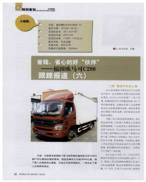
省钱、省心的好“伙伴”——福田欧马可C280跟踪报道(六)
能 改 成气 刹 , 车 这
开始 的刹车效 果还
上 就 觉得后 背处 漏风 , 知道 哪里密封 不
是 很 不 错 的 但 现 在 的 效 果 有所 减 弱 j 二
不 严 了; 就 是 这 车 有 地 方 设 计 得 不 合 再 理 车 厢 与 梁 之 间 有 个 螺 丝 造 成 梁 受 力
题 : 次 去 河 北 行 驶 过 程 中突 然 刹 车 就 有 没 了, 时 1 当 京出 一 身冷 汗 I 曼用 挡 位 把 , 曼1
感 谢 徐 飞 跃 和 王 大轩 两 位 师 傅 半 年 来 对
这 次 系 列 报 道 的 积 极 配 合 对 他 们 的 意
见 和 建 议 期 待 着 欧 马可 C 8 Байду номын сангаас 纳 百 川 、 20 纳 谏 如 流 . 则 改 之 、 则 加 勉 。只 有 无
做 但 我 觉 得 随 着 客 户 的 慢 慢 积 累 , 活
肯 定 会 越 来 越 多 , 年 收 回 成 本 应 该 没 问 2
题 。
王大轩建议这个螺丝设计到别的地方
拉着1 多的酒去哈 尔滨 , 来 觉得这车 吨 本 有 几 点 建 议 提 一 下 : 是 希 望 刹 车
的 密 封 性 好 是 一 大优 点 可 那 次 在 高 速
F 0 H RUCKUSERS蝗". 0 W ET LT L ' 别 r刀 策 qJ
是 这 里 的 收 费 比 较 高 , 选 择 了最 常 规 只 的保 养 项 目就 花 了 5 0 , 超 出 了自己 6元 这 的预 期 三 是 附 加 服 务 不 到 位 一 般 除 了 保 养 项 目外 , 务 人 员 还 会 给 车 做 一 个 服 比较 全 面 的 检 查 , 如 刹 车 系 统 、 光 系 比 灯 统 等 , 这 里 没 有给 检 查 任 何 地 方 , 一 但 这
- 1、下载文档前请自行甄别文档内容的完整性,平台不提供额外的编辑、内容补充、找答案等附加服务。
- 2、"仅部分预览"的文档,不可在线预览部分如存在完整性等问题,可反馈申请退款(可完整预览的文档不适用该条件!)。
- 3、如文档侵犯您的权益,请联系客服反馈,我们会尽快为您处理(人工客服工作时间:9:00-18:30)。
海德牌小型扫路车各地用户使用照片
图为:海德牌小型扫路车在北京西站进行保洁,用户反映良好
图为:北京电视台播出的海德牌小型扫路车在北京大栅栏进行保洁的
专题报道,反映良好
图为:整装待发北京市朝阳区环境卫生服务中心的小型扫路车
图为:出口泰国整装待发的海德牌小型扫路车
图为:海德牌小型扫路机在泰国曼谷进行城市道路保洁,
当地用户反映良好
图为:整装待发上海市普陀区绿化和市容管理局的海德牌小型扫路车
图为:整装待发三亚市园林环卫局的海德牌小型扫路车
图为:海德牌小型扫路车在一汽集团进行保洁,反映良好。