ABAQUSconnector典范用法介绍
ABAQUSconnector经典用法介绍

Connection Elements and ConnectionLibraryLecture 2Copyright 2006 ABAQUS, Inc.L2.2 Overview•Introduction•Defining Connector Elements•Understanding Connector Sections•Understanding Connection Types•Understanding Connector Local Directions•Rotational Degrees of Freedom at Nodes•Components of Relative Motion•Connector Local Kinematics•Summary of Orientations and Local DirectionsFlexible Multibody Systems with ABAQUSCopyright 2006 ABAQUS, Inc.Copyright 2006 ABAQUS, Inc.IntroductionFlexible Multibody Systems with ABAQUSL2.4Copyright 2006 ABAQUS, Inc.Introduction•General characteristics of connector elements•Connector elements model discrete (point-to-point) physical connections between deformable or rigid bodies or can be connected to ground.•Example: typical connections in automotive suspension systemsTypical connections in automotive suspensionRack and pinion Control armTie rodKnuckleStrutJOIN CYLINDRICALAXIALCYLINDRICALLINKFlexible Multibody Systems with ABAQUSL2.5Copyright 2006 ABAQUS, Inc.Introduction•Connector elements have relative displacements and rotations that are local to the element, which are referred to as components of relative motions (CORM).•Connector elements impose kinematic constraints. For example:•Door connected to a frame through a hinge •Two panels of sheet metal spot welded together •Constant velocity joints•Connector elements may include (nonlinear) force-versus-displacement (or velocity) behavior in their available components of relative motion. •Example: muscle force resisting the rotation of a knee joint in a crash-test occupant dummy model.•Connector elements can provide comprehensive kinematic and kinetic output describing the connection.Flexible Multibody Systems with ABAQUSL2.6Copyright 2006 ABAQUS, Inc.Introduction•Connector elements are functionally defined by specifying the connection attributes.•Connection types•For example: axial, hinge, weld, constant velocity joints, link,beam, etc.•Local connector directions•Connector behaviors•Uncoupled or coupled response•Linear or nonlinear response •Elasticity and damping •Plasticity •Friction•Damage and Failure •Stops and locks AXIAL connection in a shock absorbingstrut uses a variety of connection behaviors, including spring, damping and stopbehaviorsAXIALDefining Connector ElementsCopyright 2006 ABAQUS, Inc.L2.8 Defining Connector Elements•Connector elements are 2-node elements.•Element type:•CONN2D2•Two-dimensional analysis•Axisymmetric analysis•CONN3D2•Three-dimensional analysis•Both types of element have at most two nodes.•The position (location, orientation) and motion (displacement, velocity,acceleration) of the second node on the element are measured relative tothe first node.Flexible Multibody Systems with ABAQUSCopyright 2006 ABAQUS, Inc.Flexible Multibody Systems with ABAQUSL2.9Copyright 2006 ABAQUS, Inc.Defining Connector Elements•Defining a connector element –Keywords interface•To connect two points:*ELEMENT, TYPE=[CONN2D2 or CONN3D2]element number , first node number , second node number•Example: Shock absorber*ELEMENT, TYPE=CONN3D2101, 11, 12Simplified connector model of a shock absorberab1Flexible Multibody Systems with ABAQUSL2.10Copyright 2006 ABAQUS, Inc.Defining Connector Elements•To connect a point to ground:•The ground “node”can be the first or second node on the connectorelement.*ELEMENT, TYPE=nameelement number , , node number on the bodyor*ELEMENT, TYPE=nameelement number , node number on the body•The ground node is fixed.2L2.11 Defining Connector Elements•Defining connector geometry –ABAQUS/CAE interface•Create assembly-level wire features to defineconnector geometry in the Interaction module.•disjoint wires•chained wires•wires to ground.•Click Add to add points•Tip: two coincident points can beselected simultaneously by double-clickingon the location of the points•Click Delete to delete the selected point pair.•Click Swap to swap the points of the selectedpoint pair.•Tip: the point pair needs to be selected byclick its index number.Flexible Multibody Systems with ABAQUSCopyright 2006 ABAQUS, Inc.L2.12 Defining Connector Elements• A geometry set including all of the wires can becreated when creating the wire feature.•The set can be used during the subsequentselection procedures.•For example, you can use sets to assignconnector sections, request output, orprescribe motions.•Note: Multiple sets can be mergedinto a new set using the set mergefeature.•Assembly-level wire features cannot be modifieddirectly once created.•Wires can be removed by selecting RemoveWires From Feature.Flexible Multibody Systems with ABAQUSCopyright 2006 ABAQUS, Inc.Flexible Multibody Systems with ABAQUSL2.13Copyright 2006 ABAQUS, Inc.Defining Connector Elements•Example: Truck door hinges•In this example, hinge connectors connect a truck door to the truck body.ABAQUS/CAE interface Create wire geometryKeywords interface Define a connector element*ELEMENT, TYPE=CONN3D2, ELSET=CONN_DOOR_HINGE 620601, 9000009, 9000010620602, 9000011, 9000012...2 nodes per elementRP-2node 9000010HINGE connectorsat door hingesCopyright 2006 ABAQUS, Inc.Understanding Connector SectionsFlexible Multibody Systems with ABAQUSL2.15Copyright 2006 ABAQUS, Inc.Understanding Connector Sections•Connector section defines:•The connection type.•The local directions associated with the connector’s nodes •The connector behaviors.•Note: Details of connector behavior will be discussed in lectures 4 and 5.•Creating a connector section*CONNECTOR SECTION, ELSET=nameABAQUS/CAE interfaceKeywords interfaceFlexible Multibody Systems with ABAQUSL2.16Copyright 2006 ABAQUS, Inc.Understanding Connector Sections•Defining the connection type•Basic connection components•Translations •Rotations•Assembled connection components•Combination of basic connection componentsKeywords interfaceABAQUS/CAE interface*CONNECTOR SECTION, ELSET =name basic connection type, <basic connection type>or*CONNECTOR SECTION, ELSET=name assembled connectionFlexible Multibody Systems with ABAQUSL2.17Copyright 2006 ABAQUS, Inc.Understanding Connector Sections•Example: Truck door hinges –Keywords interface•Define and assign a connector section*ELEMENT, TYPE=CONN3D2, ELSET=CONN_DOOR_HINGE 620601,9000009,9000010620602,9000011,9000012*CONNECTOR SECTION , ELSET=CONN_DOOR_HINGE HINGE ...Assembled connection; one can also use basic connection types: JOIN and REVOLUTE .Connector elements CONN_DOOR_HINGE(assignment)Flexible Multibody Systems with ABAQUSL2.18Copyright 2006 ABAQUS, Inc.Understanding Connector Sections•Example: Truck door hinges –ABAQUS/CAE interface•Define and assign a connector section•Define a connector sectionAssembled Hinge connection;one can also use basic connection types: JOIN and REVOLUTE.No behavior options are specified (default).Note: Details will be discussed in lectures 4 and 5.1Flexible Multibody Systems with ABAQUSL2.19Copyright 2006 ABAQUS, Inc.Understanding Connector Sections•Assign a connector section•Connector section assignment is used to assign a connector section to a region (wires) of the model.Assign the connection section DOOR_HINGES to the wire Wire-1-DOOR_HINGES .2Copyright 2006 ABAQUS, Inc.Understanding Connection TypesFlexible Multibody Systems with ABAQUSL2.21Copyright 2006 ABAQUS, Inc.Understanding Connection Types•Connection types•The connection-type library contains:•Translational basic connection components, which affecttranslational DOFs at both nodes and may affect rotational DOFs at the first node of the connector element.•Rotational basic connection components, which affect only rotational DOFs at both nodes of the connector element •Assembled connections , which are a predefined combination of translational and rotational basic connection components.•The above choices determine which element local DOFs exist.•Given the number of connection types available, it is clear that connector elements can easily be customized to suit an application.Flexible Multibody Systems with ABAQUSL2.22Copyright 2006 ABAQUS, Inc.•Examples of translational basic connections :•AXIAL –Provide a connection between two nodes that acts along the line connecting the nodes.•CARTESIAN –Provide a connection between two nodes that allows independent behavior in three local Cartesian directions.•JOIN –Join the position of two nodes.•ACCELEROMETER –Provide a connection between two nodes to measure the relative acceleration, velocity, and position of a body in a local coordinate system.•Available only in 3D analysis in ABAQUS/Explicit. •Will be converted internally to a CARTESIAN connector type in ABAQUS/Standard.bau 1b ab aAXIALJOINCARTESIANACCELEROMETERUnderstanding Connection TypesFlexible Multibody Systems with ABAQUSL2.23Copyright 2006 ABAQUS, Inc.•Examples of rotational basic connections:•REVOLUTE –Provides a revolute connection between two nodes.•CARDAN –Provides arotational connection between two nodes parameterized by Cardan angles.•EULER –Provides a rotational connection between two nodes parameterized by Euler anglesREVOLUTECARDANEULERUnderstanding Connection TypesFlexible Multibody Systems with ABAQUSL2.24Copyright 2006 ABAQUS, Inc.Understanding Connection TypesBasic rotational Basic translational ROTATION-ACCELEROMETER SLOTROTATIONSLIDE-PLANE UNIVERSALREVOLUTE RADIAL-THRUST PROJECTION FLEXION-TORSION PROJECTION CARTESIAN FLEXION-TORSIONLINKEULERJOIN CONSTANT VELOCITY CARTESIAN CARDANAXIAL ALIGN ACCELEROMETER ab aSummary of basic connection typesFlexible Multibody Systems with ABAQUSL2.25Copyright 2006 ABAQUS, Inc.•Examples of assembled connections:•BEAM –provides a rigid beam connection between two nodes (JOIN + ALIGN)•HINGE –joins the position of two nodes, and provides a revolute connection between their rotational degrees of freedom (JOIN + REVOLUTE)•UJOINT –joins the position of two nodes, and provides a universal connection between their rotational degrees of freedom at the nodes (JOIN + UNIVERSAL)abBEAMHINGE UJOINTUnderstanding Connection TypesFlexible Multibody Systems with ABAQUSL2.26Copyright 2006 ABAQUS, Inc.Understanding Connection TypesJOINJOIN SLOT SLIDE-PLANE JOINSLOT JOIN PROJECTION CARTESIAN JOINEquivalent basic connection components(translational + rotational)Assembled ALIGNWELDUNIVERSAL UJOINT ALIGN TRANSLATOR REVOLUTE PLANAR REVOLUTE HINGE REVOLUTE CYLINDRICAL CONSTANT VELOCITY CVJOINT PROJECTIONFLEXION-TORSION BUSHINGALIGNBEAMSummary of assembled connection typesL2.27 Understanding Connection Types•More advanced connection types, such as FLOW-CONVERTER,RETRACTOR and SLIPRING, are also available.•These connectors are special pulley-type connectors used to modelseatbelt kinematics.•These connection types will not be discussed here but are discussedfurther in Appendix1.•Example: Three-point belt model with retractor and pretensioner.Video ClipVideo Clip Flexible Multibody Systems with ABAQUSCopyright 2006 ABAQUS, Inc.Understanding Connector LocalDirectionsCopyright 2006 ABAQUS, Inc.Flexible Multibody Systems with ABAQUSL2.29Copyright 2006 ABAQUS, Inc.•Understanding connector local directions•Orientations are used to define local directions for connection types that use local directions (local directions may be required or optional)•The local directions are defined by reference to a local orientation or coordinate system.•Example: HINGE connector requires an orientation to be associated with the first node a .•The hinge axis is aligned with the orientation X -direction.(local orientation)XUnderstanding Connector Local DirectionsFlexible Multibody Systems with ABAQUSL2.30Copyright 2006 ABAQUS, Inc.•Not all connection type require the local directions (e.g. LINK).•In some cases default local directions are chosen (e.g. CARTESIAN)•Local directions at the second node are not used by all connection types.•Example: SLOT connection•The line of the slot is defined by the first local direction at node a and the initial position of node b . (fig. a)•The SLOT connection constrains the position of node b (x b ) to remain on the line of the slot.•Note: different results would be obtained if different orientations are used for the local directions. (figs. b, c)21u 1u 112b. Orientation pointing from node a to node bc. 45o counterclockwise rotation of the slota. SLOT connectionaUnderstanding Connector Local DirectionsFlexible Multibody Systems with ABAQUSL2.31Copyright 2006 ABAQUS, Inc.Understanding Connector Local Directions•The default directions at the second node are the local directions at the first node.•It may be necessary to define local directions at the second node to model the mechanism correctly, e.g. UJOINT.•In geometrically nonlinear analyses, the element local directionsassociated with the nodes rotate with the rotational degrees of freedom at the nodes.• A summary of connector local directions will be in the section “Summary of Orientations and Local Directions”in this lecture.Flexible Multibody Systems with ABAQUSL2.32Copyright 2006 ABAQUS, Inc.•Defining connector orientation•Example: Truck door hingesZ YXORI_CONN_DOORABAQUS/CAE interface Define orientation using a datum coordinate systemKeywords interfaceDefine orientation using local CSYS*ORIENTATION , NAME=ORI_CONN_DOOR 0.,0.,1., 1.,0.,0.3,0Understanding Connector Local DirectionsFlexible Multibody Systems with ABAQUSL2.33Copyright 2006 ABAQUS, Inc.•Example: Truck door hinges*ORIENTATION, NAME=ORI_CONN_DOOR 0.,0.,1.,1.,0.,0.3,0*ELEMENT, TYPE=CONN3D2, ELSET=CONN_DOOR_HINGE 620601,9000009,9000010620602,9000011,9000012*CONNECTOR SECTION, ELSET=CONN_DOOR_HINGE HINGEORI_CONN_DOORConnector elements CONN_DOOR_HINGEKeywords interfaceZ YXORI_CONN_DOORUnderstanding Connector Local DirectionsFlexible Multibody Systems with ABAQUSL2.34Copyright 2006 ABAQUS, Inc.•Specify local orientations for the endpoints of the wires –ABAQUS/CAE interface.•Connector section assignment is used to specify local orientations for the endpoints of the wires.•Example: Truck door hingesZ YXORI_CONN_DOORUnderstanding Connector Local DirectionsRotational Degrees of Freedom at theNodesCopyright 2006 ABAQUS, Inc.L2.36 Rotational Degrees of Freedom at the Nodes•Overview•In geometrically nonlinear analyses, the element local directionsassociated with the nodes rotate with the rotational degrees offreedom at the nodes.•In linear or perturbation analyses, the element local directionsremain fixed.•In cases where an orientation definition is permitted for definingconnection directions (either required or optional), the connectorelement will activate rotational degrees of freedom at the nodes if theydo not exist already.•The only exception is JOIN (will be discussed later).Flexible Multibody Systems with ABAQUSCopyright 2006 ABAQUS, Inc.L2.37 Rotational Degrees of Freedom at the Nodes•Example: The BEAM connection activates rotational degrees of freedom.The solid elements do not provide rotational stiffness at these DOFs; theconnector does NOT transmit rotation into the solid.Flexible Multibody Systems with ABAQUSCopyright 2006 ABAQUS, Inc.L2.38 Rotational Degrees of Freedom at the Nodes•Other connections where an orientation definition is permitted activaterotational degrees of freedom (e.g. BEAM, …):•If local directions are used and either the element's nodes do not possessrotational DOFs or if rotational constraints such as,•Equations•Multi-point constraints•Boundary conditionsare not applied to the nodes, numerical singularities associated withunconstrained degrees of freedom will exist.•Solutions:•Attach the connector element to a structural element.•Add rotational boundary conditions.•Use coupling constraints (Recommended)Flexible Multibody Systems with ABAQUSCopyright 2006 ABAQUS, Inc.Flexible Multibody Systems with ABAQUSL2.39Copyright 2006 ABAQUS, Inc.Rotational Degrees of Freedom at the Nodes•JOIN connection does NOT activate rotational degrees of freedom•This allows the user to define a join constraint between two solids expressed only in terms of translations.•Example 1: Two deformable solids connected by the JOIN connection type rotate under certain loading and boundary conditions.•Orientation at node a does not rotate with the rotation of thedeformable body since the solid element does not have rotational DOFs actived.Deformable12XY ZJOINDeformable C3D8RC3D8RDeformable CLOADCLOADDeformable12JOINabNote: The examples discussed here and the next two slides consider geometric nonlinearity.Flexible Multibody Systems with ABAQUSL2.40Copyright 2006 ABAQUS, Inc.Rotational Degrees of Freedom at the Nodes•Example 2: Make one solid in Example 1rigid.•Orientation at node a rotates with the rotation of the rigid body since the rigid body has rotational DOFs.•Node b will move accordingly with node a .12XY ZJOINRigid C3D8RC3D8RDeformable CLOADCLOAD12J O I N RigidDeformableRPa bFlexible Multibody Systems with ABAQUSL2.41Copyright 2006 ABAQUS, Inc.Rotational Degrees of Freedom at the NodesXY ZJOIN b213aSurface-basedcoupling constraintDeformableC3D8R DeformableC3D8R12J O I N DeformableDeformableCLOADCLOAD•Example 3: Define a surface-based coupling constraint on the surface of one of the deformable solids in Example 1; choose the reference point of the surface-based coupling constraint as node a .•Orientation at node a rotates with the rotation of the deformable body since the coupling constraint actives rotational DOFs.•Node b will move accordingly with node a .Copyright 2006 ABAQUS, Inc.Components of Relative MotionL2.43 Components of Relative Motion•Components of relative motion•Connector elements have internal DOFs that do not exist at any node,but are a part of the connector element itself.•The connector local degrees of freedom, that is, the three translationsand three rotations relative to the connector element local coordinatesystem (in three dimensions), are called the components of relativemotion (CORM).•The three translations are in the element local coordinate directions.•The three rotations are angular quantities that depend on thespecific connection definition and may or may not be rotations aboutorthogonal directions.•All components of relative motion are either constrained or available.•The definitions of constrained and available components of relativemotion will be discussed in next two slides, respectively.Flexible Multibody Systems with ABAQUSCopyright 2006 ABAQUS, Inc.L2.44 Components of Relative Motion•Constrained components of relative motion•Constrained components of relative motion are displacements androtations that are fixed by the connector element.•ABAQUS/Standard uses Lagrange multipliers to enforce the kinematicconstraints.•The constraint forces and moments carried by the element appearas additional solution variables.•ABAQUS/Explicit uses an augmented Lagrange technique to enforce thekinematic constraints.•Constrained components of relative motion are measured by reactionforces and moments.•The kinematic constraint is equivalent to forcing one or more of thecomponents of relative motion to behave according to some predefinedrelationship.Flexible Multibody Systems with ABAQUSCopyright 2006 ABAQUS, Inc.Flexible Multibody Systems with ABAQUSL2.45Copyright 2006 ABAQUS, Inc.Components of Relative Motion•Available components of relative motion•Available components of relative motion are displacements and rotations that are not constrained kinematically.•Available components of relative motion can be used for•Defining material-like behavior (discussed in lectures 4 and 5).•Specifying connector actuation (discussed in lecture 6).•Time-dependent motion •Applying loading•Assigning complex interactions, such as contact or friction (discussed in lecture 4).Flexible Multibody Systems with ABAQUSL2.46Copyright 2006 ABAQUS, Inc.Components of Relative Motion•Examples:3+1:3+2:3+3:0:2: 3: u 1=u 2=u 3=00:0:Kinematic constraints 2: ur 1, ur 3U-JOINT1: ur 1HINGE 0:BEAM 3: ur 1, ur 2, ur 3CARDAN/EULER 1: ur 1REVOLUTE 0:JOIN 3: u 1, u 2, u 3CARTESIAN 1: u 1AXIAL Available components Connection types ⋅=⋅=a b a b 12130,0e e e e ⋅=⋅=a b a b 12130,0e e e e u 1=u 2=u 3=0u 1=u 2=u 3=0⋅=a b 130e e ur 1=ur 2=ur 3=0u 1=u 2=u 3=0–For other connection types refer to “Connection-type library”section 25.1.5 in ABAQUS Analysis User’sManual.Connector Local KinematicsCopyright 2006 ABAQUS, Inc.L2.48 Connector Local Kinematics•There are many different kinematic quantities used to describe aconnector element:•Position•Displacement•Velocity•Acceleration•Reference position for defining constitutive response•Constitutive displacements (essentially material strains)•All these quantities provide useful information regarding the connectorelement.Flexible Multibody Systems with ABAQUSCopyright 2006 ABAQUS, Inc.L2.49 Connector Local Kinematics•In three dimensions each of the above kinematic quantities requires sixcomponents to completely define it.•Three components in two dimensions.•For example, in three dimensions, a position requires•Three generalized coordinates to identify the location of the secondnode relative to the first.•Three angles to identify the orientation of the second node relativeto the first.•In two dimensions, a position requires•Two generalized coordinates to identify the location of the secondnode relative to the first.•One angle to identify the orientation of the second node relative tothe first.Flexible Multibody Systems with ABAQUSCopyright 2006 ABAQUS, Inc.L2.50 Connector Local Kinematics•Displacement, velocity, acceleration•These quantities are derived from position:•Displacement = change in position•Velocity = rate of change of position•Acceleration = rate of change of velocity•The reference position for constitutive response and constitutivedisplacements is relevant only for material behavior and will bediscussed in Lecture 4.Flexible Multibody Systems with ABAQUSCopyright 2006 ABAQUS, Inc.L2.51 Connector Local Kinematics•Translations:•With the exception of RADIAL-THRUST, BUSHING, PROJECTIONCARTESIAN and AXIAL, all the connections use Cartesian coordinatesto locate the second node relative to the first.•For translations the second node’s position, displacement, velocity,etc. are identified by three Cartesian components relative to localdirections at the connector element’s first node.•RADIAL-THRUST uses a cylindrical coordinate system with origin at thefirst node.•BUSHING and PROJECTION CARTESIAN use an orthonormal systemthat follows the systems at both nodes in the connection.•AXIAL does not use a coordinate system. The CORM is measured alongthe line separating the two nodes in the connection.Flexible Multibody Systems with ABAQUSCopyright 2006 ABAQUS, Inc.L2.52 Connector Local Kinematics•Rotations:•Describing directions at the second node relative to directions at the firstnode is much more complicated.•Example: REVOLUTE•Several different rotation parameterizations are used.•Cardan angles and Euler angles are successive rotation parameterizations.Examples:•Spinning top = EULER angles (precession, nutation, and spin).•Airplane attitude = CARDAN angles (roll, pitch, and yaw).Flexible Multibody Systems with ABAQUSCopyright 2006 ABAQUS, Inc.L2.53 Connector Local Kinematics•The rotation vector is a parameterization similar to the nodal rotationaldegrees of freedom in ABAQUS.•Example: Instantaneous angular velocity•FLEXION-TORSION has rotation parameterization angles consisting of totalflexion, torsion, and sweep.•PROJECTION FLEXION-TORSION connection has rotationparameterization angles consisting of two component flexion angles and atorsion angle.•Example: Head position on the shoulders in a crash test dummy model.•Different rotation parameterizations are analogous to different coordinate systems (Cartesian versus cylindrical versus polar, etc.).•Use the one that makes the most sense for a particular application.Flexible Multibody Systems with ABAQUSCopyright 2006 ABAQUS, Inc.Summary of Orientation and LocalDirectionsCopyright 2006 ABAQUS, Inc.Flexible Multibody Systems with ABAQUSL2.55Copyright 2006 ABAQUS, Inc.•Summary of connector local directions in different connection types.Summary of Orientation and Local DirectionsOptional **Optional **AXIAL Ignored Required RADIAL-THRUST Ignored Ignored LINKIgnored Optional *JOIN Optional Optional ACCELEROMETEROptional Optional PROJECTION CARTESIANIgnoredRequiredSLOTIgnored Required SLIDE-PLANEIgnored Optional CARTESIAN2nd node 1st node Connection Type Local Directions at Connector Nodes –Basic Translational*Rotational dofs are not activated. If rotational dofs do not exist, the local coordinate system does not co-rotate and fixed directions are used.**Optional only at a ground node. Otherwise, ignored.Flexible Multibody Systems with ABAQUSL2.56Copyright 2006 ABAQUS, Inc.Summary of Orientation and Local DirectionsLocal Directions at Connector Nodes –Basic RotationalOptional Required UNIVERSAL Optional Optional ROTATION-ACCELEROMETERIgnoredRequiredFLOW-CONVERTEROptional Required REVOLUTEOptional Required PROJECTION FLEXION-TORSIONOptional Required FLEXION-TORSIONOptional Required EULER Optional Required CONSTANT VELOCITYOptional Required CARDANOptional Optional ALIGN Optional Optional ROTATION 2nd node 1st node Connection TypeFlexible Multibody Systems with ABAQUSL2.57Copyright 2006 ABAQUS, Inc.Summary of Orientation and Local DirectionsLocal Directions at Connector Nodes –AssembledOptional Optional WELD IgnoredIgnoredSLIPRINGOptional Required UJOINT Optional Required TRANSLATOROptional Required PLANAR Optional Required HINGE Optional Required CYLINDRICALOptional Required CVJOINT Optional Required BUSING Optional Optional BEAM 2nd node 1st node Connection TypeFlexible Multibody Systems with ABAQUSL2.58Copyright 2006 ABAQUS, Inc.Summary of Orientation and Local Directions•Example: the definitions of orientation and local directions in UJOINTUnit angular velocity at node 1 about shaft 1axis, what is shaft 2rotation after 1 sec?*ELEMENT, TYPE=CONN3D2, ELSET=UJOINT_EL3,2,3*CONNECTOR SECTION, ELSET=UJOINT_ELUJOINT,ORI_SHAFT_1,ORI_SHAFT_2*ORIENTATION, NAME=ORI_SHAFT_10.0,0.0,1.0, 1.0,0.0,0.0*ORIENTATION, NAME=ORI_SHAFT_20.0,0.0,1.0, 0.937,0.342,0.0*TRANSFORM, NSET=NODE40. 937,0.342,0.0, -0.342,0.937,0.0*BOUNDARY, TYPE=VELOCITY 1,4,4,1.0*NODE PRINT, NSET=NODE4, GLOBAL=NO U,β=20oω1ω2Shaft 1Shaft 21234UJOINT:if drive shaft moves at constant angular velocity, for β≠0, driven shaft moves with uneven angular velocity (it “wobbles”)driven shaft twist angle = α2= arctan[cos(β) tan(ω1t )]local 2 axes along shaft axesfix U 1,U 2,U 3fix UR 2,UR 3fix U 1,U 2,U 3UR 1 in local coord. system is 0.971(Note: arctan[cos(20ο) tan(1.0∗1.0)]=0.971O.K.)align local 1 direction at node 4 with shaft 2axisStep time = 1.0sec1global axes231’2’3’1’2’3’。
abaqus使用技巧

关于reference point如果你用CAE建立模型,那么开始需要你选择是否刚体还是变形体如果是刚体,在part里就可以定义了,不需要加任何刚体约束,不需要定义材料如果你是做的变形体(需要材料定义)然后采用刚体约束,在assembly里定义第二章ABAQUS 基本使用方法[2](pp15)快捷键:Ctrl+Alt+左键来缩放模型;Ctrl+Alt+中键来平移模型;Ctrl+Alt+右键来旋转模型。
②(pp16)ABAQUS/CAE 不会自动保存模型数据,用户应当每隔一段时间自己保存模型以避免意外丢失。
[3](pp17)平面应力问题的截面属性类型是Solid(实心体)而不是Shell(壳)。
ABAQUS/CAE 推荐的建模方法是把整个数值模型(如材料、边界条件、载荷等)都直接定义在几何模型上。
载荷类型Pressure 的含义是单位面积上的力,正值表示压力,负值表示拉力。
[4](pp22)对于应力集中问题,使用二次单元可以提高应力结果的精度。
[5](pp23)Dismiss 和Cancel 按钮的作用都是关闭当前对话框,其区别在于:前者出现在包含只读数据的对话框中;后者出现在允许作出修改的对话框中,点击Cancel 按钮可关闭对话框,而不保存所修改的内容。
[6](pp26)每个模型中只能有一个装配件,它是由一个或多个实体组成的,所谓的“实体”(instance)是部件(part)在装配件中的一种映射,一个部件可以对应多个实体。
材料和截面属性定义在部件上,相互作用(interaction)、边界条件、载荷等定义在实体上,网格可以定义在部件上或实体上,对求解过程和输出结果的控制参数定义在整个模型上。
[7](pp26) ABAQUS/CAE 中的部件有两种:几何部件(native part)和网格部件(orphan mesh part)。
创建几何部件有两种方法:(1)使用Part 功能模块中的拉伸、旋转、扫掠、倒角和放样等特征来直接创建几何部件。
Abaqus操作说明.doc
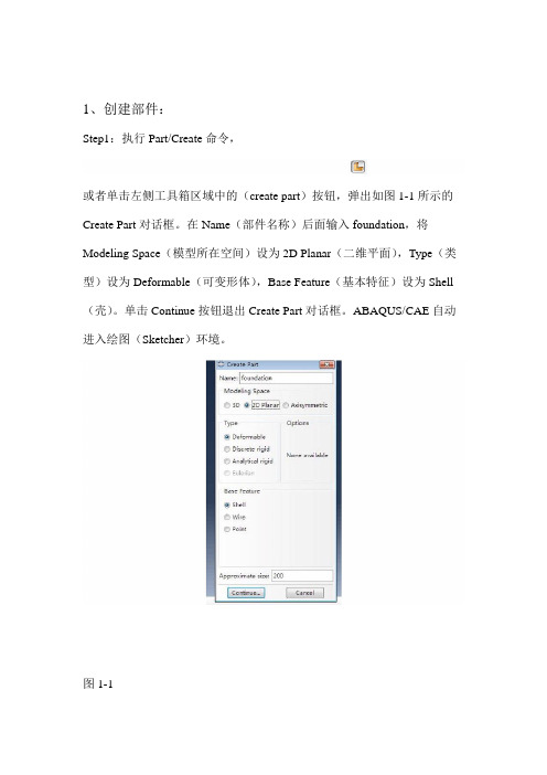
1、创建部件:Step1:执行Part/Create命令,或者单击左侧工具箱区域中的(create part)按钮,弹出如图1-1所示的Create Part对话框。
在Name(部件名称)后面输入foundation,将Modeling Space(模型所在空间)设为2D Planar(二维平面),Type(类型)设为Deformable(可变形体),Base Feature(基本特征)设为Shell (壳)。
单击Continue按钮退出Create Part对话框。
ABAQUS/CAE自动进入绘图(Sketcher)环境。
图1-1Step2:选择绘图工具框右上方的创建矩形工具,在窗口底部的提示区显示“Pick a starting corner for the rectangle—or enter X,Y”,输入坐标(0,0),按下Enter键,在窗口底部的提示区显示“Pick the opposite corner for the rectangle—or enter X,Y”,输入(45.5,20),按下Enter键。
单击Done,创建part完成,如图1-2。
图1-2Step3:单击左侧工具箱区域中的,弹出如图1-3的窗口。
应用或功能将groundwork(基础)在foundation的位置绘制出来,点击Done,返回图1-4所示窗口图1-3图1-4Step4:执行Tools-Set-Create弹出如图1-5的Create Set对话框,在Name 后面输入all,点击Continue,将整个foundation模块选中如图1-6所示,点击Done,完成集合all的创建。
以相同的操作,将图1-4中的小矩形区域创建Name为remove的集合。
图1-5图1-6以相同的方式分别创建名称为:groundwork,retaining,backfill的part,依次如图1-7,1-8,1-9所示。
abaqus部分名词定义及解释

Assembly (装配)功能模块定义空间位置Step (分析步)功能模块(l)初始分析步(initial)ABAQUS/CAE自动创建一个初始分析步,可以在其中定义模型初始状态下的边界条件和相互作用(interaction)。
初始分析步只有一个,名称是"Initial",它不能被编辑、重命名、替换、复制或删除。
(2)后续分析步(analysis step )在初始分析步之后,需要创建一个或多个后续分析步,每个后续分析步描述一个特定的分析过程,例如载荷或边界条件的变化、部件之间相互作用的变化、添加或去除某个部件等等:设定输出数据(Result file )fil可供第三方记事本编辑。
设定自适应网格Interaction (相互作用)功能模块在Interaction 功能模块中,主要可以定义模型的以下相互作用。
1.Interaction 定义模型的各部分之间或模型与外部环境之间的力学或热相互作用,例如接触、弹性地基、热辐射等。
2.Constraint 定义模型各部分之间的约束关系。
3.Connector 定义模型中的两点之间或模型与地面之间的连接单元( connector),用来模拟固定连接、钱接、恒定速度连接、止动装置、内摩擦、失效条件和锁定装置等。
4.Special →Inertia 定义惯量(包括点质量/惯量、非结构质量和热容)。
5.Special →Crack 定义裂纹。
6.Special →Springs/Dashpots定义模型中的两点之间或模型与地面之间的弹簧和阻尼器。
7.主菜单Tools 常用的菜单项包括Set (集合)、Surface (面)和AlE\plitude (幅值)等。
说明:接触即使两实体之间或一个装配件的两个区域之间在空间位置上是互相接触的,ABAQUS/CAE 也不会自动认为它们之间存在着接触关系,需要使用interaction模块中的主菜单Interacton 来定义这种接触关系。
ABAQUS基本使用方法

ABAQUS 分析步骤使用ABAQUS进行有限元分析包括三个步骤:使用ABAQUS/CAE或其他前处理器进行前处理使用ABAQUS/Standard或ABAQUS/Explicit进行分析计算使用ABAQUS/Viewer进行后处理ABAQUS/CAE简介1)ABAQUS/CAE的模型数据库保存在扩展名为.cae的文件中,每个ABAQUS模型中只能有一个装配件(assembly),它是由一个或多个实体(instance)组成的,一个部件(part)可以对应多个实体。
2)ABAQUS/CAE由以下功能模块构成:Part(部件)、Property(特性)、Assembly(装配)Step(分析步)、Interaction(相互作用)、Load(载荷)Mesh(网格)、Job(分析作业)、Visualization(后处理)Sketch(绘图)。
3)Part模块的主要功能包括:创建、编辑和管理部件,通过创建特征(feature)来定义部件的几何形状,指定刚体部件的参考点。
4)Property模块的主要功能包括:创建和管理材料、截面属性、梁截面,指定部件的截面属性、取向、法线方向和切线方向。
5)Assembly模块的主要功能包括:创建、合并和切割实体,为实体定位。
6)Step模块的主要功能包括:创建分析步,设定输出数据,设定自适应网格,控制求解过程。
7)Interaction模块的主要功能是定义相互作用(例如接触)、约束、连接件、惯量、裂纹、弹簧和阻尼器。
8)Load模块的主要功能是定义载荷、边界条件、场变量和载荷状况。
9)Mesh模块的主要功能包括:布置网格种子,设置单元形状、单元类型、网格划分技术和算法、划分网格,检验网格质量。
10)Job模块的主要功能包括:创建分析作业,提交和运行分析作业,生成INP文件,监控分析作业的运行状态,中止分析作业的运行。
11)Sketch模块的主要功能是绘制二维平面图。
CAE_Abaqus在连接器分析中的应用

4.
Mating Force analysis
是不是P 和C 越大越容易收敛?
page 21
4.
Mating Force analysis
1 . PRESSURE- OVERCLOSURE= EXPONENTIAL parameter effect
c0 and p0 are the values for this surface behavior’ s parameter, we can tune these values to solve convergence problem or get a
Analysis contacts’ spring rate so that contact deflections could be allocated between upper and lower contacts by their spring rate. No contact sequence analysis because memory card would contact upper and lower contact at the same time.
Value 0 36 1.00 0.64
• Contact NF analysis • Allocated the deflection averagely to upper and lower contact to do NF analysis.
K=296.6gf/mm
K=277gf/mm
Upper contact
MF _ 插入力; _ 摩擦力= N *f;f _ 摩擦系数 式2中的N 代入式1
求得: MF
f
(9 )]
A
C )] = P*
4 ABAQUS基本使用方法
河南工业大学机电学院
Visualization
ABAQUS基本使用方法-功能模块
河南工业大学机电学院
Visualization
ABAQUS基本使用方法-功能模块
河南工业大学机电学院
Mesh
ABAQUS基本使用方法-功能模块
河南工业大学机电学院
Mesh
ABAQUS基本使用方法-功能模块
河南工业大学机电学院
河南工业大学机电学院
Load
ABAQUS基本使用方法-功能模块
河南工业大学机电学院
Load
ABAQUS基本使用方法-功能模块
河南工业大学机电学院
Load
ABAQUS基本使用方法-功能模块
河南工业大学机电学院
Mesh
ABAQUS基本使用方法-功能模块
河南工业大学机电学院
Job
ABAQUS基本使用方法-功能模块
河南工业大学机电学院
Step
通用分析步 和线性摄动 分析步
ABAQUS基本使用方法-功能模块
河南工业大学机电学院
Step
几何非线性
ABAQUS基本使用方法-功能模块
河南工业大学机电学院
Step
ABAQUS基本使用方法-功能模块
河南工业大学机电学院
Step
场变量输出
ABAQUS基本使用方法-功能模块
Mesh
ABAQUS基本使用方法-功能模块
河南工业大学机电学院
Mesh
ABAQUS基本使用方法-功能模块
河南工业大学机电学院
Mesh
ABAQUS基本使用方法-功能模块
河南工业大学机电学院
Mesh
ABAQUS基本使用方法-功能模块
ABAQUS入门使用手册[1].
ABAQUS 入门使用手册ABAQUS 简介:ABAQUS 是一套先进的通用有限元程序系统,这套软件的目的是对固体和结构的力学问题进行数值计算分析, 而我们将其用于材料的计算机模拟及其前后处理,主要得益于 ABAQUS 给我们的 ABAQUS/Standard及ABAQUS/Explicit通用分析模块。
ABAQUS 有众多的分析模块,我们使用的模块主要是 ABAQUS/CAE及 Viewer, 前者用于建模及相应的前处理, 后者用于对结果进行分析及处理。
下面将对这两个模块的使用结合本人的体会做一些具体的说明:一. ABAQUS/CAECAE 模块用于分析对象的建模, 特性及约束条件的给定, 网格的划分以及数据传输等等,其核心由七个步骤组成,下面将对这七个步骤作出说明: 1.PART 步(1 Part →CreatModeling Space:① 3D 代表三维② 2D 代表二维③ Aaxisymmetric 代表轴对称,这三个选项的选定要视所模拟对象的结构而定。
Type: ① Deformable 为一般选项,适合于绝大多数的模拟对象。
② Discrete rigid 和 Analytical rigid用于多个物体组合时,与我们所研究的对象相关的物体上。
ABAQUS 假设这些与所研究的对象相关的物体均为刚体,对于其中较简单的刚体, 如球体而言, 选择前者即可。
若刚体形状较复杂, 或者不是规则的几何图形, 那么就选择后者。
需要说明的是, 由于后者所建立的模型是离散的, 所以只能是近似的,不可能和实际物体一样,因此误差较大。
Shape 中有四个选项,其排列规则是按照维数而定的,可以根据我们的模拟对象确定。
Type: ① Extrusion 用于建立一般情况的三维模型② Revolution 建立旋转体模型③ Sweep 用于建立形状任意的模型。
Approximate size:在此栏中设定作图区的大致尺寸,其单位与我们选定的单位一致。
abaqus connector
Abaqus中connector介绍及与samcef 在connector方面对比:在Abaqus中,应用不同的elements进行建模分析。
运动副及主要连接关系属于abaqus 的连接单元(connector elements)。
连接类型主要分为basic types, assembled types, complex types, and MPC types。
连接都属于刚性连接。
Abaqus中的柔性连接主要依靠special-purpose elements实现,例如其中的flexible joint elements。
而samcef的装配关系都集中在assembly 中,能够同时处理线性和非线性问题,有少数几个与samcef中的assembly关系对应。
Assembly中连接关系可以直接用于柔性部件的连接,相对于abaqus及其他多体软件的装配更方便容易。
1.在ABAQUS-Basic types中主要包括平移关系,普通旋转关系(只对连接的两个节点的转动自由度起作用)和特殊旋转关系(不只对连接节点的转动自由度起作用)三大类。
(1)平移关系:ACCELEROMETER:测量两连接点之间的相对运动速度,加速度,位移等关系。
AXIAL:连接两点,方向沿两点连接线CARTESIAN及PROJECTION CARTESIAN:确定两节点在局部笛卡尔坐标系下的相互依附关系JOIN:连接两点,与samcef的fixed对应LINK:两节点的刚性连接,使之保持一定间距RADIAL-THRUST :使两点在径向和推力方向能够各自出现位移SLIDE-PLANE :使第二个节点保持在预定平面上,平面由第一个点的方向及第二个点的初始位置确定SLOT :使第二个点在一条直线上,这条直线由第一个点的方向和第二个点的初始位置确定(2)旋转关系:ALIGN,,CARDAN (万向节),CONSTANT VELOCITY,FLEXION-TORSION (弯曲扭曲),PROJECTION FLEXION-TORSION(两个弯曲转动和一个扭曲转动),REVOLUTE ,ROTATION ,UNIVERSAL :万向连接;等(3)特殊的旋转关系:与材料有关的FLOW-CONVERTER(Provide a means of converting the material flow ,degree of freedom 10,at a connector node into a rotation)2. assembled types主要为上述基本副的组合HINGE为平移(JOIN)与旋转副(REVOLUTE)的组合,可以连接两点并在他们旋转方向上进行一定约束,对应于samcef的Hinge,但在samcef中此单元可以定义motor及controllerBUSHING:不会限制任何运动,需要使用局部坐标系等效于(PROJECTIONCARTESIAN + PROJECTION FLEXION-TORSION)。
ABAQUS有限元软件基本操作说明
Abaqus仿真分析操作说明1.单位一致性(未列出参照国际单位)长度:米(m)力:牛(N)质量:千克(kg)时间:秒(s)强度(压力):帕(Pa)能量:焦耳(J)密度:千克/立方米(kg/m3)加速度:米/平方秒(m/s2)2.模型(part)的建立首先用三维绘图软件(CAD、PROE、SOLIDEDGE、SOLIDWORKS等)将模型画好。
3.模型(part)导入ABAQUS软件①将模型另存为sat或stp(step),示意图如下;文件名最好存为英文字母。
②模型另存为sat或stp(step)格式后,到“选项”进行设置,设置完成后将模型另存好(存放位置自设,能找到就好),示意图如下;③打开已经安装好的ABAQUS 软件,选中左上角“文件→导入→部件”,示意图如下;4. 模型(part)的参数设置和定义导出模型单位由mm 改为m 。
选中后隐藏的部件不能导入ABAQUS 软件。
版本设为ABAQUS 软件版本。
双击所有参数均为默认,确定就好。
到上面这一步骤,模型导入已经完成,接下来就是一些参数的设置和分析对象的定义。
具体的分析步骤按照下图所示一步一步完成即可。
(1)“属性”步完成材料的定义。
具体参数设置见下图:(1)(2)(3)(4)(5)(7)(6)1.双击“创建材料”2.自定义名称4.在“通用”下双击“密度”进行参数设置5.输入材料密度,单位kg/m3。
6.在“力学”下双击“弹性”进行参数设置。
7.输入材料杨氏模量(Pa)和泊松比(无单位),单击“确定”完成参数设置。
8.双击“创建截面”,“类别”和“类型”默认。
9.单击“继续”。
10.参数默认,单击“确定”。
11.双击“指定截面”。
(2)“装配”步完成分析对象的选定。
具体操作见下图:12.单击模型指定截面。
13.单击“完成”,完成截面指定。
14.模型变绿,指定截面成功;同时“属性”步参数定义结束。
1.切换到下一步(装配)。
3.选中要分析的部件,单击“确定”,完成“装配”步。
- 1、下载文档前请自行甄别文档内容的完整性,平台不提供额外的编辑、内容补充、找答案等附加服务。
- 2、"仅部分预览"的文档,不可在线预览部分如存在完整性等问题,可反馈申请退款(可完整预览的文档不适用该条件!)。
- 3、如文档侵犯您的权益,请联系客服反馈,我们会尽快为您处理(人工客服工作时间:9:00-18:30)。
Connection Elements and ConnectionLibraryLecture 2Copyright 2006 ABAQUS, Inc.L2.2 Overview•Introduction•Defining Connector Elements•Understanding Connector Sections•Understanding Connection Types•Understanding Connector Local Directions•Rotational Degrees of Freedom at Nodes•Components of Relative Motion•Connector Local Kinematics•Summary of Orientations and Local DirectionsFlexible Multibody Systems with ABAQUSCopyright 2006 ABAQUS, Inc.Copyright 2006 ABAQUS, Inc.IntroductionFlexible Multibody Systems with ABAQUSL2.4Copyright 2006 ABAQUS, Inc.Introduction•General characteristics of connector elements•Connector elements model discrete (point-to-point) physical connections between deformable or rigid bodies or can be connected to ground.•Example: typical connections in automotive suspension systemsTypical connections in automotive suspensionRack and pinion Control armTie rodKnuckleStrutJOIN CYLINDRICALAXIALCYLINDRICALLINKFlexible Multibody Systems with ABAQUSL2.5Copyright 2006 ABAQUS, Inc.Introduction•Connector elements have relative displacements and rotations that are local to the element, which are referred to as components of relative motions (CORM).•Connector elements impose kinematic constraints. For example:•Door connected to a frame through a hinge •Two panels of sheet metal spot welded together •Constant velocity joints•Connector elements may include (nonlinear) force-versus-displacement (or velocity) behavior in their available components of relative motion. •Example: muscle force resisting the rotation of a knee joint in a crash-test occupant dummy model.•Connector elements can provide comprehensive kinematic and kinetic output describing the connection.Flexible Multibody Systems with ABAQUSL2.6Copyright 2006 ABAQUS, Inc.Introduction•Connector elements are functionally defined by specifying the connection attributes.•Connection types•For example: axial, hinge, weld, constant velocity joints, link,beam, etc.•Local connector directions•Connector behaviors•Uncoupled or coupled response•Linear or nonlinear response •Elasticity and damping •Plasticity •Friction•Damage and Failure •Stops and locks AXIAL connection in a shock absorbingstrut uses a variety of connection behaviors, including spring, damping and stopbehaviorsAXIALDefining Connector ElementsCopyright 2006 ABAQUS, Inc.L2.8 Defining Connector Elements•Connector elements are 2-node elements.•Element type:•CONN2D2•Two-dimensional analysis•Axisymmetric analysis•CONN3D2•Three-dimensional analysis•Both types of element have at most two nodes.•The position (location, orientation) and motion (displacement, velocity,acceleration) of the second node on the element are measured relative tothe first node.Flexible Multibody Systems with ABAQUSCopyright 2006 ABAQUS, Inc.Flexible Multibody Systems with ABAQUSL2.9Copyright 2006 ABAQUS, Inc.Defining Connector Elements•Defining a connector element –Keywords interface•To connect two points:*ELEMENT, TYPE=[CONN2D2 or CONN3D2]element number , first node number , second node number•Example: Shock absorber*ELEMENT, TYPE=CONN3D2101, 11, 12Simplified connector model of a shock absorberab1Flexible Multibody Systems with ABAQUSL2.10Copyright 2006 ABAQUS, Inc.Defining Connector Elements•To connect a point to ground:•The ground “node”can be the first or second node on the connectorelement.*ELEMENT, TYPE=nameelement number , , node number on the bodyor*ELEMENT, TYPE=nameelement number , node number on the body•The ground node is fixed.2L2.11 Defining Connector Elements•Defining connector geometry –ABAQUS/CAE interface•Create assembly-level wire features to defineconnector geometry in the Interaction module.•disjoint wires•chained wires•wires to ground.•Click Add to add points•Tip: two coincident points can beselected simultaneously by double-clickingon the location of the points•Click Delete to delete the selected point pair.•Click Swap to swap the points of the selectedpoint pair.•Tip: the point pair needs to be selected byclick its index number.Flexible Multibody Systems with ABAQUSCopyright 2006 ABAQUS, Inc.L2.12 Defining Connector Elements• A geometry set including all of the wires can becreated when creating the wire feature.•The set can be used during the subsequentselection procedures.•For example, you can use sets to assignconnector sections, request output, orprescribe motions.•Note: Multiple sets can be mergedinto a new set using the set mergefeature.•Assembly-level wire features cannot be modifieddirectly once created.•Wires can be removed by selecting RemoveWires From Feature.Flexible Multibody Systems with ABAQUSCopyright 2006 ABAQUS, Inc.Flexible Multibody Systems with ABAQUSL2.13Copyright 2006 ABAQUS, Inc.Defining Connector Elements•Example: Truck door hinges•In this example, hinge connectors connect a truck door to the truck body.ABAQUS/CAE interface Create wire geometryKeywords interface Define a connector element*ELEMENT, TYPE=CONN3D2, ELSET=CONN_DOOR_HINGE 620601, 9000009, 9000010620602, 9000011, 9000012...2 nodes per elementRP-2node 9000010HINGE connectorsat door hingesCopyright 2006 ABAQUS, Inc.Understanding Connector SectionsFlexible Multibody Systems with ABAQUSL2.15Copyright 2006 ABAQUS, Inc.Understanding Connector Sections•Connector section defines:•The connection type.•The local directions associated with the connector’s nodes •The connector behaviors.•Note: Details of connector behavior will be discussed in lectures 4 and 5.•Creating a connector section*CONNECTOR SECTION, ELSET=nameABAQUS/CAE interfaceKeywords interfaceFlexible Multibody Systems with ABAQUSL2.16Copyright 2006 ABAQUS, Inc.Understanding Connector Sections•Defining the connection type•Basic connection components•Translations •Rotations•Assembled connection components•Combination of basic connection componentsKeywords interfaceABAQUS/CAE interface*CONNECTOR SECTION, ELSET =name basic connection type, <basic connection type>or*CONNECTOR SECTION, ELSET=name assembled connectionFlexible Multibody Systems with ABAQUSL2.17Copyright 2006 ABAQUS, Inc.Understanding Connector Sections•Example: Truck door hinges –Keywords interface•Define and assign a connector section*ELEMENT, TYPE=CONN3D2, ELSET=CONN_DOOR_HINGE 620601,9000009,9000010620602,9000011,9000012*CONNECTOR SECTION , ELSET=CONN_DOOR_HINGE HINGE ...Assembled connection; one can also use basic connection types: JOIN and REVOLUTE .Connector elements CONN_DOOR_HINGE(assignment)Flexible Multibody Systems with ABAQUSL2.18Copyright 2006 ABAQUS, Inc.Understanding Connector Sections•Example: Truck door hinges –ABAQUS/CAE interface•Define and assign a connector section•Define a connector sectionAssembled Hinge connection;one can also use basic connection types: JOIN and REVOLUTE.No behavior options are specified (default).Note: Details will be discussed in lectures 4 and 5.1Flexible Multibody Systems with ABAQUSL2.19Copyright 2006 ABAQUS, Inc.Understanding Connector Sections•Assign a connector section•Connector section assignment is used to assign a connector section to a region (wires) of the model.Assign the connection section DOOR_HINGES to the wire Wire-1-DOOR_HINGES .2Copyright 2006 ABAQUS, Inc.Understanding Connection TypesFlexible Multibody Systems with ABAQUSL2.21Copyright 2006 ABAQUS, Inc.Understanding Connection Types•Connection types•The connection-type library contains:•Translational basic connection components, which affecttranslational DOFs at both nodes and may affect rotational DOFs at the first node of the connector element.•Rotational basic connection components, which affect only rotational DOFs at both nodes of the connector element •Assembled connections , which are a predefined combination of translational and rotational basic connection components.•The above choices determine which element local DOFs exist.•Given the number of connection types available, it is clear that connector elements can easily be customized to suit an application.Flexible Multibody Systems with ABAQUSL2.22Copyright 2006 ABAQUS, Inc.•Examples of translational basic connections :•AXIAL –Provide a connection between two nodes that acts along the line connecting the nodes.•CARTESIAN –Provide a connection between two nodes that allows independent behavior in three local Cartesian directions.•JOIN –Join the position of two nodes.•ACCELEROMETER –Provide a connection between two nodes to measure the relative acceleration, velocity, and position of a body in a local coordinate system.•Available only in 3D analysis in ABAQUS/Explicit. •Will be converted internally to a CARTESIAN connector type in ABAQUS/Standard.bau 1b ab aAXIALJOINCARTESIANACCELEROMETERUnderstanding Connection TypesFlexible Multibody Systems with ABAQUSL2.23Copyright 2006 ABAQUS, Inc.•Examples of rotational basic connections:•REVOLUTE –Provides a revolute connection between two nodes.•CARDAN –Provides arotational connection between two nodes parameterized by Cardan angles.•EULER –Provides a rotational connection between two nodes parameterized by Euler anglesREVOLUTECARDANEULERUnderstanding Connection TypesFlexible Multibody Systems with ABAQUSL2.24Copyright 2006 ABAQUS, Inc.Understanding Connection TypesBasic rotational Basic translational ROTATION-ACCELEROMETER SLOTROTATIONSLIDE-PLANE UNIVERSALREVOLUTE RADIAL-THRUST PROJECTION FLEXION-TORSION PROJECTION CARTESIAN FLEXION-TORSIONLINKEULERJOIN CONSTANT VELOCITY CARTESIAN CARDANAXIAL ALIGN ACCELEROMETER ab aSummary of basic connection typesFlexible Multibody Systems with ABAQUSL2.25Copyright 2006 ABAQUS, Inc.•Examples of assembled connections:•BEAM –provides a rigid beam connection between two nodes (JOIN + ALIGN)•HINGE –joins the position of two nodes, and provides a revolute connection between their rotational degrees of freedom (JOIN + REVOLUTE)•UJOINT –joins the position of two nodes, and provides a universal connection between their rotational degrees of freedom at the nodes (JOIN + UNIVERSAL)abBEAMHINGE UJOINTUnderstanding Connection TypesFlexible Multibody Systems with ABAQUSL2.26Copyright 2006 ABAQUS, Inc.Understanding Connection TypesJOINJOIN SLOT SLIDE-PLANE JOINSLOT JOIN PROJECTION CARTESIAN JOINEquivalent basic connection components(translational + rotational)Assembled ALIGNWELDUNIVERSAL UJOINT ALIGN TRANSLATOR REVOLUTE PLANAR REVOLUTE HINGE REVOLUTE CYLINDRICAL CONSTANT VELOCITY CVJOINT PROJECTIONFLEXION-TORSION BUSHINGALIGNBEAMSummary of assembled connection typesL2.27 Understanding Connection Types•More advanced connection types, such as FLOW-CONVERTER,RETRACTOR and SLIPRING, are also available.•These connectors are special pulley-type connectors used to modelseatbelt kinematics.•These connection types will not be discussed here but are discussedfurther in Appendix1.•Example: Three-point belt model with retractor and pretensioner.Video ClipVideo Clip Flexible Multibody Systems with ABAQUSCopyright 2006 ABAQUS, Inc.Understanding Connector LocalDirectionsCopyright 2006 ABAQUS, Inc.Flexible Multibody Systems with ABAQUSL2.29Copyright 2006 ABAQUS, Inc.•Understanding connector local directions•Orientations are used to define local directions for connection types that use local directions (local directions may be required or optional)•The local directions are defined by reference to a local orientation or coordinate system.•Example: HINGE connector requires an orientation to be associated with the first node a .•The hinge axis is aligned with the orientation X -direction.(local orientation)XUnderstanding Connector Local DirectionsFlexible Multibody Systems with ABAQUSL2.30Copyright 2006 ABAQUS, Inc.•Not all connection type require the local directions (e.g. LINK).•In some cases default local directions are chosen (e.g. CARTESIAN)•Local directions at the second node are not used by all connection types.•Example: SLOT connection•The line of the slot is defined by the first local direction at node a and the initial position of node b . (fig. a)•The SLOT connection constrains the position of node b (x b ) to remain on the line of the slot.•Note: different results would be obtained if different orientations are used for the local directions. (figs. b, c)21u 1u 112b. Orientation pointing from node a to node bc. 45o counterclockwise rotation of the slota. SLOT connectionaUnderstanding Connector Local DirectionsFlexible Multibody Systems with ABAQUSL2.31Copyright 2006 ABAQUS, Inc.Understanding Connector Local Directions•The default directions at the second node are the local directions at the first node.•It may be necessary to define local directions at the second node to model the mechanism correctly, e.g. UJOINT.•In geometrically nonlinear analyses, the element local directionsassociated with the nodes rotate with the rotational degrees of freedom at the nodes.• A summary of connector local directions will be in the section “Summary of Orientations and Local Directions”in this lecture.Flexible Multibody Systems with ABAQUSL2.32Copyright 2006 ABAQUS, Inc.•Defining connector orientation•Example: Truck door hingesZ YXORI_CONN_DOORABAQUS/CAE interface Define orientation using a datum coordinate systemKeywords interfaceDefine orientation using local CSYS*ORIENTATION , NAME=ORI_CONN_DOOR 0.,0.,1., 1.,0.,0.3,0Understanding Connector Local DirectionsFlexible Multibody Systems with ABAQUSL2.33Copyright 2006 ABAQUS, Inc.•Example: Truck door hinges*ORIENTATION, NAME=ORI_CONN_DOOR 0.,0.,1.,1.,0.,0.3,0*ELEMENT, TYPE=CONN3D2, ELSET=CONN_DOOR_HINGE 620601,9000009,9000010620602,9000011,9000012*CONNECTOR SECTION, ELSET=CONN_DOOR_HINGE HINGEORI_CONN_DOORConnector elements CONN_DOOR_HINGEKeywords interfaceZ YXORI_CONN_DOORUnderstanding Connector Local DirectionsFlexible Multibody Systems with ABAQUSL2.34Copyright 2006 ABAQUS, Inc.•Specify local orientations for the endpoints of the wires –ABAQUS/CAE interface.•Connector section assignment is used to specify local orientations for the endpoints of the wires.•Example: Truck door hingesZ YXORI_CONN_DOORUnderstanding Connector Local DirectionsRotational Degrees of Freedom at theNodesCopyright 2006 ABAQUS, Inc.L2.36 Rotational Degrees of Freedom at the Nodes•Overview•In geometrically nonlinear analyses, the element local directionsassociated with the nodes rotate with the rotational degrees offreedom at the nodes.•In linear or perturbation analyses, the element local directionsremain fixed.•In cases where an orientation definition is permitted for definingconnection directions (either required or optional), the connectorelement will activate rotational degrees of freedom at the nodes if theydo not exist already.•The only exception is JOIN (will be discussed later).Flexible Multibody Systems with ABAQUSCopyright 2006 ABAQUS, Inc.L2.37 Rotational Degrees of Freedom at the Nodes•Example: The BEAM connection activates rotational degrees of freedom.The solid elements do not provide rotational stiffness at these DOFs; theconnector does NOT transmit rotation into the solid.Flexible Multibody Systems with ABAQUSCopyright 2006 ABAQUS, Inc.L2.38 Rotational Degrees of Freedom at the Nodes•Other connections where an orientation definition is permitted activaterotational degrees of freedom (e.g. BEAM, …):•If local directions are used and either the element's nodes do not possessrotational DOFs or if rotational constraints such as,•Equations•Multi-point constraints•Boundary conditionsare not applied to the nodes, numerical singularities associated withunconstrained degrees of freedom will exist.•Solutions:•Attach the connector element to a structural element.•Add rotational boundary conditions.•Use coupling constraints (Recommended)Flexible Multibody Systems with ABAQUSCopyright 2006 ABAQUS, Inc.Flexible Multibody Systems with ABAQUSL2.39Copyright 2006 ABAQUS, Inc.Rotational Degrees of Freedom at the Nodes•JOIN connection does NOT activate rotational degrees of freedom•This allows the user to define a join constraint between two solids expressed only in terms of translations.•Example 1: Two deformable solids connected by the JOIN connection type rotate under certain loading and boundary conditions.•Orientation at node a does not rotate with the rotation of thedeformable body since the solid element does not have rotational DOFs actived.Deformable12XY ZJOINDeformable C3D8RC3D8RDeformable CLOADCLOADDeformable12JOINabNote: The examples discussed here and the next two slides consider geometric nonlinearity.Flexible Multibody Systems with ABAQUSL2.40Copyright 2006 ABAQUS, Inc.Rotational Degrees of Freedom at the Nodes•Example 2: Make one solid in Example 1rigid.•Orientation at node a rotates with the rotation of the rigid body since the rigid body has rotational DOFs.•Node b will move accordingly with node a .12XY ZJOINRigid C3D8RC3D8RDeformable CLOADCLOAD12J O I N RigidDeformableRPa bFlexible Multibody Systems with ABAQUSL2.41Copyright 2006 ABAQUS, Inc.Rotational Degrees of Freedom at the NodesXY ZJOIN b213aSurface-basedcoupling constraintDeformableC3D8R DeformableC3D8R12J O I N DeformableDeformableCLOADCLOAD•Example 3: Define a surface-based coupling constraint on the surface of one of the deformable solids in Example 1; choose the reference point of the surface-based coupling constraint as node a .•Orientation at node a rotates with the rotation of the deformable body since the coupling constraint actives rotational DOFs.•Node b will move accordingly with node a .Copyright 2006 ABAQUS, Inc.Components of Relative MotionL2.43 Components of Relative Motion•Components of relative motion•Connector elements have internal DOFs that do not exist at any node,but are a part of the connector element itself.•The connector local degrees of freedom, that is, the three translationsand three rotations relative to the connector element local coordinatesystem (in three dimensions), are called the components of relativemotion (CORM).•The three translations are in the element local coordinate directions.•The three rotations are angular quantities that depend on thespecific connection definition and may or may not be rotations aboutorthogonal directions.•All components of relative motion are either constrained or available.•The definitions of constrained and available components of relativemotion will be discussed in next two slides, respectively.Flexible Multibody Systems with ABAQUSCopyright 2006 ABAQUS, Inc.L2.44 Components of Relative Motion•Constrained components of relative motion•Constrained components of relative motion are displacements androtations that are fixed by the connector element.•ABAQUS/Standard uses Lagrange multipliers to enforce the kinematicconstraints.•The constraint forces and moments carried by the element appearas additional solution variables.•ABAQUS/Explicit uses an augmented Lagrange technique to enforce thekinematic constraints.•Constrained components of relative motion are measured by reactionforces and moments.•The kinematic constraint is equivalent to forcing one or more of thecomponents of relative motion to behave according to some predefinedrelationship.Flexible Multibody Systems with ABAQUSCopyright 2006 ABAQUS, Inc.Flexible Multibody Systems with ABAQUSL2.45Copyright 2006 ABAQUS, Inc.Components of Relative Motion•Available components of relative motion•Available components of relative motion are displacements and rotations that are not constrained kinematically.•Available components of relative motion can be used for•Defining material-like behavior (discussed in lectures 4 and 5).•Specifying connector actuation (discussed in lecture 6).•Time-dependent motion •Applying loading•Assigning complex interactions, such as contact or friction (discussed in lecture 4).Flexible Multibody Systems with ABAQUSL2.46Copyright 2006 ABAQUS, Inc.Components of Relative Motion•Examples:3+1:3+2:3+3:0:2: 3: u 1=u 2=u 3=00:0:Kinematic constraints 2: ur 1, ur 3U-JOINT1: ur 1HINGE 0:BEAM 3: ur 1, ur 2, ur 3CARDAN/EULER 1: ur 1REVOLUTE 0:JOIN 3: u 1, u 2, u 3CARTESIAN 1: u 1AXIAL Available components Connection types ⋅=⋅=a b a b 12130,0e e e e ⋅=⋅=a b a b 12130,0e e e e u 1=u 2=u 3=0u 1=u 2=u 3=0⋅=a b 130e e ur 1=ur 2=ur 3=0u 1=u 2=u 3=0–For other connection types refer to “Connection-type library”section 25.1.5 in ABAQUS Analysis User’sManual.Connector Local KinematicsCopyright 2006 ABAQUS, Inc.L2.48 Connector Local Kinematics•There are many different kinematic quantities used to describe aconnector element:•Position•Displacement•Velocity•Acceleration•Reference position for defining constitutive response•Constitutive displacements (essentially material strains)•All these quantities provide useful information regarding the connectorelement.Flexible Multibody Systems with ABAQUSCopyright 2006 ABAQUS, Inc.L2.49 Connector Local Kinematics•In three dimensions each of the above kinematic quantities requires sixcomponents to completely define it.•Three components in two dimensions.•For example, in three dimensions, a position requires•Three generalized coordinates to identify the location of the secondnode relative to the first.•Three angles to identify the orientation of the second node relativeto the first.•In two dimensions, a position requires•Two generalized coordinates to identify the location of the secondnode relative to the first.•One angle to identify the orientation of the second node relative tothe first.Flexible Multibody Systems with ABAQUSCopyright 2006 ABAQUS, Inc.L2.50 Connector Local Kinematics•Displacement, velocity, acceleration•These quantities are derived from position:•Displacement = change in position•Velocity = rate of change of position•Acceleration = rate of change of velocity•The reference position for constitutive response and constitutivedisplacements is relevant only for material behavior and will bediscussed in Lecture 4.Flexible Multibody Systems with ABAQUSCopyright 2006 ABAQUS, Inc.L2.51 Connector Local Kinematics•Translations:•With the exception of RADIAL-THRUST, BUSHING, PROJECTIONCARTESIAN and AXIAL, all the connections use Cartesian coordinatesto locate the second node relative to the first.•For translations the second node’s position, displacement, velocity,etc. are identified by three Cartesian components relative to localdirections at the connector element’s first node.•RADIAL-THRUST uses a cylindrical coordinate system with origin at thefirst node.•BUSHING and PROJECTION CARTESIAN use an orthonormal systemthat follows the systems at both nodes in the connection.•AXIAL does not use a coordinate system. The CORM is measured alongthe line separating the two nodes in the connection.Flexible Multibody Systems with ABAQUSCopyright 2006 ABAQUS, Inc.L2.52 Connector Local Kinematics•Rotations:•Describing directions at the second node relative to directions at the firstnode is much more complicated.•Example: REVOLUTE•Several different rotation parameterizations are used.•Cardan angles and Euler angles are successive rotation parameterizations.Examples:•Spinning top = EULER angles (precession, nutation, and spin).•Airplane attitude = CARDAN angles (roll, pitch, and yaw).Flexible Multibody Systems with ABAQUSCopyright 2006 ABAQUS, Inc.L2.53 Connector Local Kinematics•The rotation vector is a parameterization similar to the nodal rotationaldegrees of freedom in ABAQUS.•Example: Instantaneous angular velocity•FLEXION-TORSION has rotation parameterization angles consisting of totalflexion, torsion, and sweep.•PROJECTION FLEXION-TORSION connection has rotationparameterization angles consisting of two component flexion angles and atorsion angle.•Example: Head position on the shoulders in a crash test dummy model.•Different rotation parameterizations are analogous to different coordinate systems (Cartesian versus cylindrical versus polar, etc.).•Use the one that makes the most sense for a particular application.Flexible Multibody Systems with ABAQUSCopyright 2006 ABAQUS, Inc.Summary of Orientation and LocalDirectionsCopyright 2006 ABAQUS, Inc.Flexible Multibody Systems with ABAQUSL2.55Copyright 2006 ABAQUS, Inc.•Summary of connector local directions in different connection types.Summary of Orientation and Local DirectionsOptional **Optional **AXIAL Ignored Required RADIAL-THRUST Ignored Ignored LINKIgnored Optional *JOIN Optional Optional ACCELEROMETEROptional Optional PROJECTION CARTESIANIgnoredRequiredSLOTIgnored Required SLIDE-PLANEIgnored Optional CARTESIAN2nd node 1st node Connection Type Local Directions at Connector Nodes –Basic Translational*Rotational dofs are not activated. If rotational dofs do not exist, the local coordinate system does not co-rotate and fixed directions are used.**Optional only at a ground node. Otherwise, ignored.Flexible Multibody Systems with ABAQUSL2.56Copyright 2006 ABAQUS, Inc.Summary of Orientation and Local DirectionsLocal Directions at Connector Nodes –Basic RotationalOptional Required UNIVERSAL Optional Optional ROTATION-ACCELEROMETERIgnoredRequiredFLOW-CONVERTEROptional Required REVOLUTEOptional Required PROJECTION FLEXION-TORSIONOptional Required FLEXION-TORSIONOptional Required EULER Optional Required CONSTANT VELOCITYOptional Required CARDANOptional Optional ALIGN Optional Optional ROTATION 2nd node 1st node Connection TypeFlexible Multibody Systems with ABAQUSL2.57Copyright 2006 ABAQUS, Inc.Summary of Orientation and Local DirectionsLocal Directions at Connector Nodes –AssembledOptional Optional WELD IgnoredIgnoredSLIPRINGOptional Required UJOINT Optional Required TRANSLATOROptional Required PLANAR Optional Required HINGE Optional Required CYLINDRICALOptional Required CVJOINT Optional Required BUSING Optional Optional BEAM 2nd node 1st node Connection TypeFlexible Multibody Systems with ABAQUSL2.58Copyright 2006 ABAQUS, Inc.Summary of Orientation and Local Directions•Example: the definitions of orientation and local directions in UJOINTUnit angular velocity at node 1 about shaft 1axis, what is shaft 2rotation after 1 sec?*ELEMENT, TYPE=CONN3D2, ELSET=UJOINT_EL3,2,3*CONNECTOR SECTION, ELSET=UJOINT_ELUJOINT,ORI_SHAFT_1,ORI_SHAFT_2*ORIENTATION, NAME=ORI_SHAFT_10.0,0.0,1.0, 1.0,0.0,0.0*ORIENTATION, NAME=ORI_SHAFT_20.0,0.0,1.0, 0.937,0.342,0.0*TRANSFORM, NSET=NODE40. 937,0.342,0.0, -0.342,0.937,0.0*BOUNDARY, TYPE=VELOCITY 1,4,4,1.0*NODE PRINT, NSET=NODE4, GLOBAL=NO U,β=20oω1ω2Shaft 1Shaft 21234UJOINT:if drive shaft moves at constant angular velocity, for β≠0, driven shaft moves with uneven angular velocity (it “wobbles”)driven shaft twist angle = α2= arctan[cos(β) tan(ω1t )]local 2 axes along shaft axesfix U 1,U 2,U 3fix UR 2,UR 3fix U 1,U 2,U 3UR 1 in local coord. system is 0.971(Note: arctan[cos(20ο) tan(1.0∗1.0)]=0.971O.K.)align local 1 direction at node 4 with shaft 2axisStep time = 1.0sec1global axes231’2’3’1’2’3’。