图纸中的符号
施工图纸符号大全
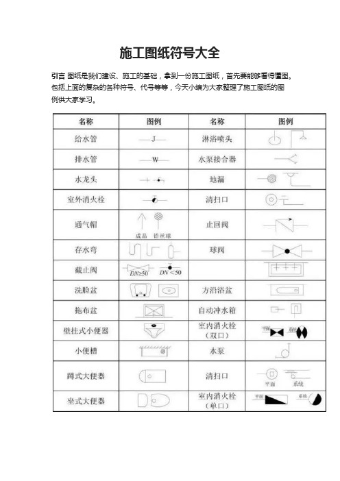
施工图纸符号大全
引言图纸是我们建设、施工的基础,拿到一份施工图纸,首先要能够看得懂图。
包括上面的复杂的各种符号、代号等等,今天小编为大家整理了施工图纸的图
例供大家学习。
一、排水工程图纸的使用中,缩写符号如下:
排水管道-W,为污水。
也有-F,是废水。
很少见有用-P 来表示的。
消火栓的管道-XH。
自动喷淋管道-Z或用-ZP。
雨水管道-Y. 。
采暖管道-R,通常实线表示供水管,虚线来表示回水管。
压力排水-PY。
冷凝水管道-N。
管道立管-L. 。
另外设备的型号字母有:
Q-流量或风量 H-扬程 N-功率 P-压力 QW-潜污泵其他阀门、器具类的都用图形来区分。
JL-给水管; WL-污水管; YL-雨水管; RJL-热给水; RHL-热回水。
二、常用建筑材料的示例图
三、常用建筑构造的示例图
四、常用建筑的构件代号含义大全
五、其他专业图纸的一些代号大全。
工程图纸符号

工程图纸符号1. 引言工程图纸是工程设计的重要组成部分,它通过符号和线条的组合来表示和传达工程设计的各种要素和信息。
工程图纸符号在工程图纸上起到了关键的作用,它们能够简洁明了地表达各种设计要素,使得设计师、工程师和施工人员能够准确地理解和解读工程图纸。
本文将介绍一些常见的工程图纸符号,包括建筑图纸、土木工程图纸和机电工程图纸等。
希望能够帮助读者更好地理解和应用工程图纸符号。
2. 建筑图纸符号建筑图纸是建筑设计的重要成果之一,它包含了建筑物的平面图、立面图、剖面图等,用于传达建筑设计的各种信息。
建筑图纸符号主要用于表示建筑物的结构、构件和材料等。
2.1 建筑物轮廓符号•直线表示墙体•虚线表示开放区域(如门、窗等)•波浪线表示屋檐或屋顶•点表示柱子•三角形表示梁•矩形表示墙体•圆形表示圆柱体(如圆柱形柱子)2.3 几何符号•圆表示柱子的底部•正方形表示柱子的顶部•菱形表示柱子的中间部分2.4 材料符号•斜线表示砖墙•点划线表示混凝土墙•虚线表示木材墙3. 土木工程图纸符号土木工程图纸主要用于表示土方工程、道路工程、桥梁工程等。
土木工程图纸符号可以帮助工程师和施工人员准确理解工程设计,并进行相应的施工和监控工作。
•等高线表示地势起伏情况•点表示点状地物(如树木、灯杆等)•虚线表示线性地物(如道路、河流等)3.2 路基符号•直线表示道路•箭头表示道路方向•虚线表示挖方或填方3.3 桥梁符号•矩形表示桥墩•梯形表示桥台•直线表示桥面3.4 施工符号•双箭头表示挖土施工•斜线表示填土施工•实心圆表示固定点4. 机电工程图纸符号机电工程图纸主要用于表示机械设备和电气设备的安装和布置。
机电工程图纸符号可以帮助工程师和施工人员理解设备的类型、尺寸和安装位置等信息。
4.1 设备符号•正方形表示发电机•圆形表示电动机•三角形表示变压器4.2 连接符号•直线表示电气连接•弯曲线表示管道连接•虚线表示气体管道4.3 流体符号•箭头表示液体流向•波浪线表示气体流动•球形表示液体储存器5. 结论工程图纸符号是工程设计中不可或缺的一部分,它通过简单、明了的符号和线条组合,传达了丰富的设计信息。
图纸常用符号
56、KZ2 是一种框架柱,编号为KZ2 57、KZZ框支柱 58、XZ芯柱
59、LZ梁上柱 60、QZ剪力墙上柱 61、YDZ约束边缘端柱 62、YAZ约束边缘暗柱
63、YJZ约束边缘转角墙柱 64、GDZ构造边缘端柱 65、GAZ构造边缘暗柱
⑶ φ8@200(2) 表示箍筋为φ8,间距为200,双肢箍。
⑷ φ8@100(4)/150(2) 表示箍筋为φ8,加密区间距100,四肢箍,非加密区间距150,双肢箍。
三、 梁上主筋和梁下主筋同时表示方法 :
⑴ 3Φ22,3Φ20 表示上部钢筋为3Φ22, 下部钢筋为3Φ20。
⑴ 2Φ20 表示两根Φ20的钢筋,通长布置,用于双肢箍。
⑵ 2Φ22+(4Φ12)表示2Φ22 为通长,4φ12架立筋,用于六肢箍。
⑶ 6Φ25 4/2 表示上部钢筋上排为4Φ25,下排为2Φ25。
⑷ 2Φ22+ 2Φ22 表示只有一排钢筋,两根在角部,两根在中部,均匀布置。
五、 梁腰中钢筋表示方法:
79、WKL屋面框架梁 80、KZL框支梁 81、L非框架梁 82、XL悬挑梁
83、JSL井式梁 84、LPB梁板筏基础平板 85、JCL基础次梁 86、JZL基础主梁
87、jL1(16)250×350 基础梁,编号为基础梁1,有16跨,断面为宽250×高350。
25、 框支梁 KZL 26、 屋面框架梁 WKL 27、檩条 LT 28、屋架 WJ 29、托架 TJ
30、天窗架 CJ 31、框架 KJ 32、刚架 GJ 33、支架 ZJ 34、柱 Z 35、框架柱 KZ
36、构造柱 GZ 37、承台 CT 38、设备基础 SJ 39、桩 ZH 40、 挡土墙 DQ
图纸符号大全图解
图纸符号大全图解图纸符号是工程设计中非常重要的一部分,它是工程师们沟通交流的重要工具。
图纸符号的正确理解和运用对于工程设计的准确性和高效性至关重要。
因此,今天我们将为大家详细解读图纸符号大全,希望能够帮助大家更好地理解和运用图纸符号。
1. 线条符号。
在图纸中,线条符号是最基础的符号之一。
不同的线条符号代表着不同的含义,如实线代表物体的轮廓,虚线代表隐藏的边缘,粗实线代表切割平面等。
正确理解和运用线条符号可以帮助工程师们准确地表达设计意图。
2. 尺寸符号。
尺寸符号是用来表示物体尺寸大小的符号,包括直径、长度、宽度等。
常见的尺寸符号有直径符号、半径符号、角度符号等。
在图纸中,尺寸符号的正确标注可以帮助制造工人们准确地制作零件,保证产品质量。
3. 表面符号。
表面符号用来表示零件的表面加工要求,如光洁度、粗糙度、平面度等。
不同的表面符号代表着不同的加工要求,工程师们需要根据实际情况选择合适的表面符号,以确保产品的质量。
4. 符号标识。
符号标识是用来表示特定要求或特殊工艺的符号,如焊接符号、装配符号、注塑符号等。
这些符号的正确运用可以帮助工程师们准确地表达设计意图,同时也方便制造工人们进行生产。
5. 材料符号。
材料符号用来表示零件的材料种类,如钢材、铝材、铜材等。
正确标注材料符号可以帮助制造工人们选择合适的材料进行加工,保证产品的使用性能和安全性。
6. 其他符号。
除了上述几种常见的符号外,图纸中还包括了许多其他的符号,如电气符号、液压符号、气动符号等。
这些符号在不同的工程设计中扮演着重要的角色,工程师们需要根据实际情况进行正确的选择和运用。
总结。
图纸符号大全图解是工程设计中不可或缺的一部分,它通过简洁明了的符号语言,帮助工程师们准确地表达设计意图,同时也方便制造工人们进行生产加工。
因此,正确理解和运用图纸符号对于工程设计的准确性和高效性至关重要。
希望本文能够帮助大家更好地理解和运用图纸符号,提高工程设计的质量和效率。
土木工程专业设计图纸符号大全

土木工程专业设计图纸符号大全1. 标题符号- A1 标题符号表示图纸的主题,一般位于图纸的左上角。
- A1.1 指示符号表示图纸的编号和版本信息,包括图纸编号、图纸名称、日期等。
2. 尺寸符号- B1 尺寸符号用来表示图纸上的尺寸信息,包括长度、宽度、高度等。
- B1.1 长度尺寸符号表示线段的长度。
- B1.2 高度尺寸符号表示物体的高度。
- B1.3 宽度尺寸符号表示物体的宽度。
3. 断面符号- C1 断面符号表示物体的截面形状,一般用于表示建筑结构的断面。
- C1.1 矩形断面符号表示物体具有矩形截面。
- C1.2 圆形断面符号表示物体具有圆形截面。
4. 角度符号- D1 角度符号用来表示图纸上的角度信息。
- D1.1 弧度符号表示角度以弧度计量。
- D1.2 度数符号表示角度以度数计量。
5. 符号颜色- E1 符号颜色表示图纸上的不同元素或特定含义的符号所对应的颜色。
- E1.1 红色表示警示或危险。
- E1.2 蓝色表示建筑结构相关的元素。
- E1.3 绿色表示环境保护相关的元素。
6. 文字符号- F1 文字符号用来表示图纸上的文字信息。
- F1.1 标题文字符号表示图纸的标题。
- F1.2 标注文字符号表示图纸上的注释或标记。
7. 图例符号- G1 图例符号用来表示图纸上的图例信息,一般位于图纸的右上角。
- G1.1 施工图例符号表示建筑施工图纸上的图例。
- G1.2 设备图例符号表示设备布置图纸上的图例。
以上是土木工程专业设计图纸中常见的符号大全,希望对您有所帮助。
参考文献:。
建筑工程图纸符号大全

建筑工程图纸符号大全一、柱编号二、墙柱编号三、墙梁编号注:(××A)为一端悬挑,(××B)为两端悬挑,悬挑不计入跨数。
五、板编号六、板带编号注:(××A)为一端悬挑,(××B)为两端悬挑,悬挑不计入跨数。
八、板相关构造编号九、钢筋符号一级钢:A 二级钢:B 三级钢:C构件类型 代号 序号 跨数及有无悬挑 暗梁AL××(××)(××A )或(××B )构造类型 代号 序号 说明纵筋加强带 JQD ×× 以单向加强纵筋取代原位配筋后浇带 HJD ×× 有不同的留筋方式 柱帽 ZM × ×× 适用于无梁楼盖局部升降板 SJB ×× 板后即配筋与所在板相同,构造升降高度≤300 板加腋 JY ×× 腋高与腋宽可选注板开洞 BD ×× 最大边长或直径<1000;加强筋长度有全跨贯通和自洞边锚固两种 板翻边 FB ××翻遍高度≤300角部加强筋Crs×× 以上部双向非贯通加强钢筋取代原位置的非贯通配筋悬挑板阴角附加筋 Cis ×× 板悬挑阴角上部斜向附加钢筋 悬挑板阳角附加筋 Ces ×× 板悬挑阳角上部放射筋抗冲切箍筋 Rh ×× 通长用于无柱帽无梁楼盖的柱顶 抗冲切弯起筋 Rb×× 通长用于无柱帽无梁楼盖的柱顶。
施工图纸符号大全
施工图纸符号大全施工图纸是建筑工程中不可或缺的重要文件,它详细描述了建筑物的设计、构造和施工过程。
施工图纸中使用了许多特定的符号和标记,这些符号代表着不同的建筑元素和设备。
本文将介绍施工图纸中常用符号的含义和解释,帮助读者更好地理解和应用这些建筑符号。
一、基础符号1、直线:在施工图纸中,直线代表物体的轮廓或边界。
例如,墙壁、天花板和地面都可以用直线表示。
2、圆:圆通常用来表示圆形物体或曲面。
例如,管道的接头、阀门的阀座和排水管的管帽都可以用圆表示。
3、矩形:矩形通常用来表示方形物体或平面。
例如,窗户、门和墙壁都可以用矩形表示。
4、弧形:弧形代表曲线形状的物体或表面。
例如,穹顶、拱形门和曲线墙面都可以用弧形表示。
二、设备符号1、电器符号:在施工图纸中,电器符号代表各种电气设备和部件,如电线、开关、插座和灯具等。
每个符号都代表不同的电器元素,例如灯泡表示灯具,方框表示开关。
2、管道符号:管道符号代表各种管道和流体系统,如水管、气管、油管和排水管等。
每个符号都代表不同的管道元素,例如圆圈表示管道的接头,箭头表示管道的方向。
三、结构符号1、楼板符号:楼板符号代表建筑物的楼层和地面。
每个符号都代表不同的楼板元素,例如实线表示楼板的边缘,虚线表示楼板的开孔。
2、柱子符号:柱子符号代表建筑物中的支撑柱。
每个符号都代表不同的柱子元素,例如矩形表示实心柱,圆形表示圆柱。
四、其他符号1、尺寸符号:在施工图纸中,尺寸符号用于标注物体的尺寸和距离。
例如,箭头表示测量方向,波浪线表示连续测量。
2、标高符号:标高符号用于表示地面的高度和建筑物的水平面。
例如,三角形表示标高的高度,虚线表示相对高度。
总结:施工图纸中的符号是建筑工程中的重要语言,它们代表着不同的建筑元素和设备。
掌握这些符号的含义和使用方法对于从事建筑工程行业的专业人员来说非常重要。
本文介绍了基础符号、设备符号、结构符号和其他符号的含义和使用方法,希望能够帮助读者更好地理解和应用这些建筑符号。
建筑图纸符号大全教你识别常用符号

建筑图纸符号大全教你识别常用符号在建筑行业中,图纸是一种非常重要的交流工具,它能够准确地传达设计师的意图给工程师和建筑师,确保建筑工程的顺利进行。
图纸上运用了大量的符号,这些符号代表着各种不同的元素和特征。
因此,对建筑图纸符号的准确理解和识别对于建筑从业人员来说至关重要。
本文将为您介绍一些常见的建筑图纸符号,帮助您更好地理解和读懂建筑图纸。
1. 尺寸标识符号在建筑图纸中,尺寸标识符号用于表示建筑物各个部分的尺寸和距离。
常见的尺寸标识符号包括“H”、“W”和“D”,分别代表高度、宽度和深度。
此外,箭头也是一种常用的尺寸标识符号,用于指示尺寸的方向。
2. 线条符号线条符号在建筑图纸中起到了连接和界定各个元素的作用。
常见的线条符号包括实线、虚线、点线和粗线。
实线代表着边界和实体物体,虚线用于表示隐藏部分或次要元素,点线通常用于表示中心线或对称线,而粗线则用于显示特别重要的线条。
3. 建筑材料符号建筑图纸中的建筑材料符号用于标识建筑物中使用的材料。
常见的建筑材料符号有砖块、混凝土、木材和玻璃等。
这些符号通常通过简化图标的形式来表示,可以让读者迅速识别不同的材料种类。
4. 设备符号设备符号用于表示建筑物中的各种设备和机械元素。
例如,电灯、插座、空调和消防设备等。
这些符号常常采用标准化的图标形式,有助于工程师和施工人员对建筑物的布局和设备位置有更直观的了解。
5. 地形符号地形符号用于表示建筑物所在地的地形特征,例如山脉、河流和道路等。
这些符号通常是通过简化和符号化的方式来表示,以便更好地展示地形特点。
6. 水平符号水平符号用于描述建筑物的水平线或平面。
常见的水平符号包括水平线、平面图和等高线等。
这些符号的使用可以帮助读者更好地理解建筑物的外观和布局。
7. 建筑元素符号建筑元素符号用于标识建筑物中的各个元素,例如墙壁、窗户和门等。
这些符号通常是通过简化的图标形式来表示,以便在图纸上占用较小的空间。
8. 比例尺符号比例尺符号用于表示图纸上的尺寸和实际建筑物的尺寸之间的比例关系。
- 1、下载文档前请自行甄别文档内容的完整性,平台不提供额外的编辑、内容补充、找答案等附加服务。
- 2、"仅部分预览"的文档,不可在线预览部分如存在完整性等问题,可反馈申请退款(可完整预览的文档不适用该条件!)。
- 3、如文档侵犯您的权益,请联系客服反馈,我们会尽快为您处理(人工客服工作时间:9:00-18:30)。
图纸中的符号Straightness - a condition where an element of a surface or an axis is a straight line. —直度:一个条件,一个面元素或轴是一条直线Flatness- is the condition of a surface having all elements in one plane. —平整度:是条件,表面有所有的元素在一个平面Roundness - describes the condition on a surface of revolution (cylinder, cone, sphere) where all points of the surface intersected by any plane. —圆度:描述条件对革命的表面(圆柱,圆锥,球)在所有点的表面相交的任何飞机Cylindricity - describes a condition of a surface of revolution in which all points of a surface are equidistant from a common axis.—圆柱度:描述了一个条件的旋转面,使所有的点面距离相等,一个共同的旋转轴Profile of a Line- is the condition permitting a uniform amount of profile variation, ether unilaterally or bilaterally, along a line element of a feature.—线轮廓度:是条件允许量相同的剖面变化,醚单边或双边,沿着一条线元素的Profile of a Surface - is the condition permitting a uniform amount of profile variation, ether unilaterally or bilaterally, on a surface.—面轮廓度:是条件允许量相同的剖面变化,醚单边或双边,上表面All Around Symbol - indicating that a tolerance applies to surfaces all around the part.—周围标志:表明公差适用于所有周围的部分表面Angularity - is the condition of a surface, axis, or centerplane, which is at a specified angle from a datum plane or axis.—倾斜度:是表面,轴,或中线,这是从某一特定角度基准平面或轴Perpendicularity - is the condition of a surface, axis, or line, which is 90 deg. From a datum plane or a datum axis.—垂直度:条件是表面,轴,或线,这是90度的基准平面或基准轴Parallelism- is the condition of a surface, line, or axis, which is equidistant at all points from a datum plane or axis.—平行度:一个表面,线,或轴,这是等距离的所有点,基准平面或轴Position Tolerance - defines a zone within which the axis or center plane of a feature is permitted to vary from true (theoretically exact) position.—位置公差:定义一个区域内的轴或中心平面的一个特点是允许不同的真正的(理论上精确)位置Concentricity - describes a condition in which two or more features , in any combination, have a common axis.—同心度:描述在其中一个条件的2个或更多的功能,在任何组合,有一个共同的旋转轴Symmetry- is a condition in which a feature (or features) is symmetrically disposed about the center plane of a datum feature.—对称度:是一种状况,其中一个功能(或功能)是处理有关对称中心平面基准特征Runout- is the composite deviation from the desired form of a part surface of revolution through on full rotation (360 deg) of the part on a datum axis.—跳动:是复合偏离理想形式的一部分表面上通过革命旋转(360度)的一部分,在基准轴Total Runout - is the simultaneous composite control of all elements of a surface at all circular and profile measuring positions as the part is rotated through 360.—全跳动:是同时复合控制所有表面元素在所有圆轮廓测量位置的部分是通过旋转360Maximum Material Condition (MMC) - is that condition of a part feature wherein it contains the maximum amount ofmaterial within the stated limits of size. That is: minimum hole size and maximum shaft size.—最大材料状态:是条件的一部分功能其中包含的最高金额材料在规定的极限尺寸。
那就是:最小孔尺寸和最大轴尺寸Least Material Condition (LMC) - implies that condition of a part feature of size wherein it contains the least (minimum) amount of material, examples, largest hole size and smallest shaft size. It is opposite to maximum material condition.—最小材料状态:意味着条件的一部分功能的大小,其中也包含了最小(最低)的材料,例子,最大孔尺寸和最小轴径。
它的对面是最大材料状态。
Regardless Of Feature Size (RFS)- the condition where the tolerance of form, runout or location must be met irrespective of where the feature lies within its size tolerance.—不论大小的特征:不论大小的特征的情况下,形状公差,跳动或位置必须满足,不论在哪里,它的特点是在其尺寸公差Projected Tolerance Zone - applies to a hole in which a pin, stud, screw,etc., is to be inserted. It controls the perpendicularity of the hole tothe extent of the projection from the hole and as it relates to the matingpart clearance. The projected tolerance zone extends above the surface ofthe part to the functional length of the pin, stud, and screw relative toits assembly with the mating part.—投影公差区Tangent Plane - indicating a tangent plane is shown. The symbol is placedin the feature control frame following the stated tolerance.—切平面Free State Variations- is a term used to describe distortion of a part afterremoval of forces applied during manufacture.—自由状态的变化Diameter- indicates a circular feature when used on the field of a drawingor indicates that the tolerance is diametrical when used in a feature controlframe.—直径Basic Dimension- used to describe the exact size, profile, orientation orlocation of a feature. A basic dimension is always associated with a featurecontrol frame or datum target. (Theoretically exact dimension in ISO)—基本尺寸Reference Dimension - a dimension usually without tolerance, used forinformation purposes only. It does not govern production or inspectionoperations. (Auxiliary dimension in ISO)—参考尺寸Datum Feature - is the actual component feature used to establish a datum.—基准特征Dimension Origin - Signifies that the dimension originates from the planeestablished by the shorter surface and dimensional limits apply to the othersurface.—尺寸原—特征控制框Feature Control Frame- is a rectangular box containingthe geometric characteristics symbol, andthe form, runout or location tolerance. If necessary,datum references and modifiers applicable to the featureor the datums are also contained in the box.Conical Taper - is used to indicate taper for conical tapers. This symbolis always shown with the vertical leg to the left.—圆锥锥度Slope - is used to indicate slope for flat tapers. This symbol is alwaysshown with the vertical leg to the left.—斜坡度Counterbore/Spotface - is used to indicate a counterbore or a spotface. Thesymbol precedes the dimension of the counterbore or spotface, with no space—沉孔或锪平Countersink - is used to indicate a countersink. The symbol precedes thedimensions of the countersink with no space.—埋头孔Depth/Deep - is used to indicate that a dimension applies to the depth ofa feature. This symbol precedes the depth value with no space in between.—深度Square - is used to indicate that a single dimension applies to a squareshape. The symbol precedes the dimension with no space between.—正方形Number of Places - the X is used along with a value to indicate the numberof times a dimension or feature is repeated on the drawing.—相同的地方Arc Length - indicating that a dimension is an arc length measured on acurved outline. The symbol is placed above the dimension.—电弧长度Radius - creates a zone defined by two arcs (the minimum and maximum radii).The part surface must lie within this zone.—半径之间Between - to indicate that a profile tolerance applies to several contiguousfeatures, letters may designate where the profile tolerance begins and ends.These letters are referenced using the between symbol (since 1994) or theword between on drawings made to earlier versions of the Standard.统计公差Statistical Tolerance - i s the assigning of tolerances to relatedcomponents of an assembly on the basis of sound statistics (such as theassembly tolerance is equal to the square root of the sum of the squaresof the individual tolerances). By applying statistical tolerancing,tolerances of individual components may be increased or clearances betweenmating parts may be reduced. The increased tolerance or improved fit mayreduce manufacturing cost or improve the product's performance, but shallonly be employed where the appropriate statistical process control will beused. Therefore, consideration should be given to specifying the requiredCp and /or Cpk or other process performance indices.—基准公差Datum Target - is a specified point, line, or area on a part that isused to establish the Datum Reference Plane for manufacturing andinspection operations.。