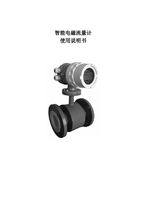
智能BFC090-B型 电磁流量计
电磁流量计FMG90B系列操作手册说明书

FMG920B-SS-VO-NPTFMG90B Series- 2 -FMG90B SeriesTechnical changes reserved- 3 -Table of contents page0 About this operating manual ...................................................................................... 4 1 Device description ..................................................................................................... 5 1.1 Delivery, unpacking and accessories ...................................................................... 5 1.2 Intended use............................................................................................................ 6 1.3 Exclusion of liability ................................................................................................. 6 2 Safety instructions ..................................................................................................... 7 3 Construction and function .......................................................................................... 8 4 Installation of FMG90B .............................................................................................. 9 4.1 Installation instructions ............................................................................................ 9 4.2 Assembly ............................................................................................................... 10 5 Electrical connection ................................................................................................ 11 5.1 Wirings .................................................................................................................. 12 6 Commissioning and measuring operation ............................................................... 13 6.1 Commissioning ...................................................................................................... 13 6.2 Switching on and off .............................................................................................. 13 6.3 Measuring operation .............................................................................................. 13 7 Maintenance and cleaning ....................................................................................... 14 8 Disassembly and disposal ....................................................................................... 15 9 Technical data ......................................................................................................... 16 9.1 Characteristics FMG90B ....................................................................................... 16 9.2 Materials table ....................................................................................................... 17 9.3 Pressure drop ........................................................................................................ 18 9.4 Dimensions (20)Copyright notice:The reproduction, distribution and utilization of this operating manual as well as the communication of its contents to others without express authorization is prohibited. Offenders will be held liable for the payment of damages. All rights reserved in the event of the grant of a patent, utility model or design.About this operating manual Series FMG90B- 4 -0 About this operating manual• The operating manual is aimed at specialists and semi-skilled personnel.•Before each step, read through the relevant advice carefully and keep to the specified order.• Thoroughly read and understand the information in the section “Safety instructions”. If you have any problems or questions, please contact your supplier or contact us directly at:Tel: (203) 359-1660 e-mail:**************Hazard signs and other symbols used:WARNING! / CAUTION! Risk of injury!This sign indicates dangers that cause personal injuries that can lead to health defects or cause considerable damage to property.CAUTION! Electric current!This sign indicates dangers which could arise from handling of electric current.CAUTION! Material damage!This sign indicates actions which could lead to possible damage to material or environmental damage.ADHERE TO OPERATING MANUAL! NOTICE!This symbol indicates important notices, tips or information. NO DOMESTIC WASTE!The device must not be disposed of together with domestic waste.Pay attention to and comply withinformation that is marked with this symbol. Follow the specified instructions and steps.Adhere to the given order.❑ Check the specified points or notices.Reference to another section, document orsource. • Item.FMG90B Series Device descriptionTechnical changes reserved - 5 -1 Device descriptionThe FMG90B series from Omega is a flow sensor without moving parts. The measurement is performed using magnetic induction.The FMG90B is used for measuring or metering water and electrically conductive fluids. The compact design and independence from the intake and discharge sections allows the FMG90B to be used under a variety of conditions.Versions:The FMG90B is available in different inner diameters from 0.12 in to 0.98 in. Type plate:You can find the type plate on the back of the FMG90B. It contains the most important technical data.1.1 Delivery, unpacking and accessoriesAll units have been carefully checked for their operational reliability before shipment. ❒ Immediately after receipt, please check the outer packaging for damages or any signs ofimproper handling.❒ Report any possible damages to the forwarder and your responsible sales representative.In such a case, state a description of the defect, the type and the serial number of the device.Report any in-transit damage immediately. Damage reported at a later date shall not be recognized. Unpacking:Carefully unpack the unit to prevent any damage.Check the completeness of the delivery based on the delivery note. Scope of delivery:❒ 1x FMG90B according to the order data. ❒ 1x Operating manual.IMPORTANT!Use the type plate to check if the delivered unit corresponds to your order.In particular, for devices with electrical components, check to see if the correct power supply voltage is specified.Device descriptionFMG90B Series- 6 -Accessories:❒ Connection cable with molded M12x1 coupling socket. ❒ M12x1 coupling socket as component.1.2 Intended useThe magnetic inductive flow sensor FMG90B must only be used for measuring and metering liquids with a minimum conductivity of 20 μS/cm.WARNING! No safety component!The magnetic inductive flow sensor of the FMG90B series is no safety component in accordance with Directive 2006/42/EC (Machine Directive). Never use the FMG90B as a safety component.The operational safety of the device supplied is only guaranteed by intended use. The specified limits (♑ § 9 "Technical data") may under no circumstances be exceeded.Before installing the device, check that the wetted materials of the device are compatible with the media being used (♑ § 9 “Technical data”).Measuring tube empty (or partially filled). / Conductivity too low.The green LED may blink irregularly if the measuring tube of the FMG90B is empty or partially filled or if the conductivity of the fluid being used is too low. Random pulses will be present at the output, but they do not represent an actual flow.Ensure that the measuring tube of the FMG90B is always completely filled (♑ § 4.1 "Installation instructions").Ensure that the conductivity of the fluid is at least 20 μS/cm.1.3Exclusion of liabilityWe accept no liability for any damage or malfunctions resulting from incorrect installation, inappropriate use of the device or failure to follow the instructions in this operating manual.FMG90B Series Safety instructionsTechnical changes reserved - 7 -2Safety instructionsBefore you install the FMG90B, read through this operating manual carefully. If theinstructions contained within it are not followed, in particular the safety guidelines, this couldresult in danger for people, the environment, and the device and the system it is connected to.The FMG90B corresponds to the state-of-the-art technology. This concerns the accuracy, the operating mode and the safe operation of the device.In order to guarantee that the device operates safely, the operator must act competently andbe conscious of safety issues.OMEGA provides support for the use of its products either personally or via relevant literature. The customer verifies that our product is fit for purpose based on our technical information. The customer performs customer- and application-specific tests to ensure that the product is suitable for the intended use. With this verification all hazards and risks aretransferred to our customers; our warranty is not valid. Qualified personnel:The personnel who are charged for the installation, operation and maintenance of theFMG90B must hold a relevant qualification. This can be based on training or relevanttuition.The personnel must be aware of this operating manual and have access to it at all times.The electrical connection should only be carried out by a fully qualified electrician. General safety instructions:In all work, the existing national regulations for accident prevention and safety in theworkplace must be complied with. Any internal regulations of the operator must also becomplied with, even if these are not mentioned in this manual. Degree of protection according to EN 60529:Please ensure that the ambient conditions at the site of use does not exceed the requirements for the stated protection rating (§ 9 "Technical data"). Prevent freezing of the medium in the device with appropriate measures.Only use the FMG90B if it is in perfect condition. Damaged or faulty devices must be checked without delay and, if necessary, replaced.When fitting, connecting and removing use only suitable appropriate tools.Do not remove or obliterate type plates or other markings on the device, as otherwise thewarranty is rendered null and void. Special safety instructions:Crystallizing liquids:Liquids which crystallize when dried out can cause a malfunction of the FMG90B. Make sure that the FMG90B is not run dry.Prevent the crystallization of the fluid in the device by taking appropriate measures.Further warnings that are specifically relevant to individual operating procedures or activities can be found at the beginning of the relevant sections of this operating manual.Construction and function FMG90B Series- 8 -3 Construction and functionComponents:① Housing:The Housing consists of plastic and has the IP65 degree of protection.② Electrical connection:The electrical connection is made via 4-pin plug M12x1.③ Operation / flow indicator LED.④ Process connection:The process connections are available in different sizes.Construction:The measuring tube with its grounding sleeves and electrodes passes through the housing and forms the external process connection of the FMG90B.A magnetic field for the measurement process is generated inside the housing, which also contains the sensor and signal conditioning circuitry.The two stainless steel electrodes are located in the middle of the measuring tube between the grounding sleeves.The FMG90B does not need any moving parts to make measurements. The inside of the measuring tube is completely open, allowing the fluid to flow unhindered through the measuring tube.Function:The magnetic inductive flow sensor functions according to the induction principle. A DC voltage is generated by the movement of a conductor in a magnetic field:The measuring tube of the FMG90B is located in a magnetic field (B).An electrically conductive medium (V) flows through the measuring tube. The positive and negative charge carriers are oppositely deflected.A voltage (U) is generated at right angles to the magnetic field, which is picked up by the two electrodes.Thereby, the induced voltage is proportional to the average flow velocity of the liquid.The electronics of the FMG90B converts the induced voltage into a flow-proportional frequency signal.FMG90B Series Installation of FMG90BTechnical changes reserved - 9 -4 Installation of FMG90BBefore installing, check that❒ the wetted materials of the device are suitable for the media being used( § 9 “Technical data”).❒ the equipment is switched off and is in a safe and de-energized state. ❒ the equipment is depressurized and has cooled down.SUITABLE TOOLS:Use only suitable tools of the correct size.4.1 Installation instructionsCAUTION! Risk of malfunction due to external magnetic fields! Magnetic fields close to the device can cause malfunctions and should be avoided.Ensure that no external magnetic fields are present at theinstallation site of the FMG90B.•The FMG90B can always be installed anywhere along the pipeline. However, straight sections of piping are preferable.Bubble-formation / run empty possibleDirt deposits possibleRun empty possibleDirt deposits possibleInstallation of FMG90BFMG90B Series• Installation can occur in horizontal and vertical pipes. The flow sensor is only suitable for application in completely filled pipe systems.•As a matter of principle magnetic inductive flow sensors are widely independent from the flow profile. An inlet section is not absolutely necessary.To reach a most highly accuracy of the measurement, you should use straight inlet and outlet sections according to the inner diameter. The inlet section has to be at least10 x inner diameter; the outlet section 5 x inner diameter in order to achieve the specified accuracy.•The inlet and outlet sections and the gaskets must have the same or a slightly larger inside diameter than the measuring tube in order to achieve the specified accuracy.•If two or more FMG90B devices are used side by side, maintain a separation of at least 1.0 in between adjacent devices.If adjacent devices are too close together, operation of both devices may be impaired due to mutual interference.4.2 AssemblyThe FMG90B is installed directly into the pipeline. The compact design and light weight of the unit make wall-mounting unnecessary.IMPORTANT NOTICES:• Only use suitable gaskets for installation.• Observe the flow direction indicated on the type plate. • Observe the mounting dimensions (♑ § 9.3 “Dimensions”).Select an appropriate location for installation(♑ § 4.1 "Installation instructions").To ensure the best possible measuring accuracy, a vertical installation position with increasing flow is preferable (no collecting of dirt deposits).Wrap the FMG90B connections with 1 to 2 wraps of threadtape (e.g. Teflon ® tape). Wrap tape in a clockwise direction, viewed form the end, leaving the first two threads uncovered. Make sure the tape does not intrude into the flow path.Attach the FMG90B with arrow pointed in the direction of flow. The fittings should be screwed into FMG90B hand tight.CAUTION! Material damage! Maximum torque 3.7 ft lb.While tightening, counter the FMG90B only by hand!If you use an open-end or a pipe wrench, the FMG90B can be damaged.To tighten the FMG90B, use an open-end or a pipe wrenchfor the fittings and only the hand for the FMG90B.FMG90B Series Electrical connection 5 Electrical connectionThe electrical connection of the FMG90B is made via the 4-pin plug M12x1 at the top of the housing.The wiring of the FMG90B depends on the ordered version. A distinction is made between frequency output or analog output and frequency output.CAUTION! Electric current!The electrical connection should only be carried out by a fully qualified electrician.De-energize the electrical system before connecting the FMG90B.Connection cable:Suitable connection cables with molded coupling socket M12x1 are available in different lengths as OMEGA accessories. The maximum permissible cable length is 10 m. Connection 4-pin plug M12x1:Screw the coupling socket of the connection cable to the plug of the FMG90B.Tighten the knurled nut of the coupling socket with a maximum torque of 1 Nm.Electrical connection FMG90B Series5.1 WiringsPinout:The pinout differs according to the chosen configuration of the device. Pinout:M12x1Possible pinout: Pin 1: +U BPin 2: n. c. (not connected) / Analog U/I Pin 3: GNDPin 4: FrequencyConnect the connection cable according to your version and the pinout on the type plate.Supply voltage:FMG90B with frequency output:Push-Pull:NPN Open Collector:PNP Open Collector:*1: Push-Pull switching outputs of several FMG90B may not be connected in parallel. *2: Recommendation Pull-Up / Pull-Down resistance R L ~2.5 k Ω (12 V) or ~5 k Ω (24 V). Ensure that the maximum signal current of 25 mA is not exceeded.Use of frequency and analog outputRecommendation for resistance R L ~2.5 k Ω (12 V) or ~5 k Ensure that the maximum signal current of 25 mA is not exceeded.FMG90B Series Commissioning and measuring operation6 Commissioning and measuring operationBefore switching on the FMG90B for the first time, please follow the instructions in the following section.6.1 CommissioningCheck that❒ the FMG90B has been installed correctly and that all screw connections are sealed. ❒ the electrical wiring has been connected properly. ❒ the measuring system is vented by flushing.6.2 Switching on and offThe FMG90B has no switch and cannot be switched on or off on its own. Switching on and off is carried out by the applied supply voltage. Switch on the supply voltage.The green LED lights up. The FMG90B is ready and goes into measuring mode.6.3 Measuring operationIn the measuring mode, the green LED flashes proportional to the measured flow.For the human eye, the flashing is no longer visible from a frequency of ~30...40 Hz.The green LED then seems to light up permanently.FMG90B with frequency output:The FMG90B provides according to the version a flow proportional NPN, PNP or Push-Pull square wave signal.The frequency of the pulse output changes according to the flow ( Fig.).FMG90B with analog output:According to the configuration of the FMG90B, the analog output provides a voltage or current signal.This signal is proportional to the measured flow. You will find the scaling of the analog output on the type plate.Maintenance and cleaning FMG90B Series7 Maintenance and cleaningMaintenance:The FMG90B is maintenance-free and cannot be repaired by the user. In case of a defect, the device must be replaced or sent back the manufacturer for repair.CAUTION! Material damage!When opening the device, critical parts or components can be damage. Never open the device and perform any repair yourself.Cleaning:Clean the FMG90B with a dry or slightly damp lint-free cloth. Do not use sharp objects or aggressive agents for cleaning.FMG90B Series Disassembly and disposal 8 Disassembly and disposalCAUTION! Risk of injury!Never remove the device from a plant in operation.Make sure that the plant is shut down professionally.Before disassembly:Prior to disassembly, ensure that❒the equipment is switched off and is in a safe and de-energized state.❒the equipment is depressurized and has cooled down.Disassembly:Remove the electrical connectors.Removethe FMG90B using suitable tools.Disposal:NO HOUSEHOLD WASTE!The FMG90B consists of various different materials. It must not be disposed of with household waste.Take the FMG90B to your local recycling plant.Technical data FMG90B Series9 Technical dataThe technical data of customized versions may differ from the data in these instructions. Please observe the information specified on the type plate.9.1 Characteristics FMG90B** Voltage output 0.5…10 V only available with 16…24 VDCFMG90B Series Technical data 9.2 Materials table* Available for FMG93B, FMG96B, FMG98BTechnical data FMG90B Series9.3Pressure dropFMG93BFMG96BFMG98B0.00.51.01.52.02.53.00.10.20.30.40.50.6P r e s s u r e d r o p ∆p [p s i ]Flow rate Q [GPM]0.00.51.01.52.02.50.250.50.7511.251.5P r e s s u r e d r o p∆p [p s i ]Flow rate Q [GPM]0.000.501.001.50123456P r e s s u r e d r o p ∆p [p s i ]Flow rate Q [GPM]FMG90B Series Technical dataFMG915B FMG920B FMG925B0.0000.1250.2500.3750.500024******** Pressuredrop∆p[psi]Flow rate Q[GPM]0.00.51.01.52.0010********Pressuredrop∆p[psi]Flow rate Q[GPM]0.00.10.20.30.40.5010203040506070 Pressuredrop∆p[psi]Flow rate Q[GPM]Technical data FMG90B Series9.4 DimensionsFMG90B:FMG925B:FMG90B Series For your notes For your notesFor your notes FMG90B Series For your notesM5759/0220FMG920B-SS-VO-NPT。
电磁流量计(上海光华)
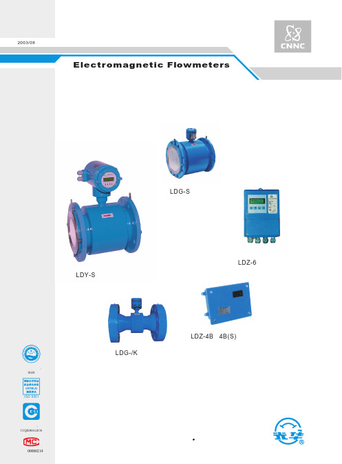
工作压力 工作电流 防护等级
最大潜水深度 5m ≤0.5A或≤0.25A IP68(防潜水)
配套 转换器型号 输出信号
显示 通讯接口 适用电源
应用
LDZ-4B、4B(S)型 LDZ-5型 、LDZ-6型 0~10mA DC或4~20mA DC
* * 频率 (脉冲) 上限1-5000Hz (上限5000CP/S)
ISO 9001
注册证号: CCQE0800A0130
沪制00000214
LDG-/K 传感器
LDZ-4B、4B(S)型 转 换 器
中国 核工 业集团公司 上海光华 仪表 厂
目 录
1.概述 ..................................................................................................................................................................1 2.工作原理...........................................................................................................................................................1 3.性能简介...........................................................................................................................................................2 4.外形和安装尺寸................................................................................................................................................5 5.电磁流量计口径的选择.....................................................................................................................................8 6.电极材料的选择..............................................................................................................................................10 7.衬里材料的选择..............................................................................................................................................11 8.防护等级的选择..............................................................................................................................................11 9.接地环的选择..................................................................................................................................................11 10.传感器在管道上的安装..................................................................................................................................11 11. 选型编码说明................................................................................................................................................16 12.电磁流量转换器............................................................................................................................................18 13.防爆合格证...................................................................................................................................................22
智能LDCK型电磁流量计使用说明书+上海九

3.1 基本参数与性能指标…………………………………………………………9
4. 转换器接线与操作 …………………………………………………………… 10
4.1 转换器键盘定义与显示………………………………………………10 4.2 转换器剖面图………………………………………………………………11 4.3 转换器接线图…………………………………………………………………12 4.4 连 接 电 线 电 缆 特 性 及 连 接 要 求 ………………………………………… 15
0.6 1.2 2.5 3.5 6 9 15 25 36 55 90 130 205 350 500 700 900 1150 1400 2000 2800 3600 4600 5600 8000
1 2 3.5 5 9 15 20 35 55 90 135 200 350 500 750 1000 1350 1700 2110 3000 4000 5500 7000 8500 12000
所有仪表在出厂前,都按用户订货时提出的量程,用水进行实流标定,量程设定都已调整 完毕。用户除检查零位外,不需任何调整,即可投入使用。若试运行时发生问题,请与本公司 联系。
本使用说明书用于上海自仪九仪表有限公司设计、生产的LDCK型电磁流量计 的安装、使用与维护。
Hale Waihona Puke 公司地址:上海市嘉定区安亭镇昌吉路157号 营 销 部:021-59577980 021-59577910 传 真:021-59564732 邮 编:201805
3.2、流量计精确度
表 3.1 VS:设定量程(m/s)
智能电磁流量计使用说明书
即为智能二次表,其将流量信号放大处理¾单片机运算后,可显示流量、累 计量,并能输出脉冲、模拟电流等信号,用于流体流量的计量或控制。
第 1 页,共 39 页
智能电磁流量计使用说明书
2.3 产品组装形式:
其分为一体型和分体型两种形式。 (1)一体型:传感器和转换器一体安装。 (2)分体型:传感器和转化器分离安装,通过连接电缆形成流量1、概述
电磁流量计是一种电磁感应式流量仪表,依据 JB/T9248-1999《电磁流量计》 设计,适用于电导率大于 5μs/cm 导电液体的流量计算;公称通径范围为 10mm 至 3000mm,是集智能化、小型轻量一体化、多功能、高精度、高可靠性为一体 的系列电磁流量计产品。它由传感器和智能转换器两部分组成。
3、功能特点
★ 适合于所有导电率大于 5μs/cm 的液体流量检测。导电率的变化不影响 性能的改变。
★ 流量计具有长期的高测量精度,实际上不受流体物理特性的影响,测 量准确度可达 0.5 级,0.3 级。
★ 流量计无机械可动部件,平时无需维护。 ★ 投运方便,流量计按 0~10m/s 范围自动设定,无需更改测量量程。 ★ 由于所有与被测介质接触的部件,均具有良好的抗腐蚀性和耐磨性,
电磁流量计有着广泛的用途,在满足现场监测显示的同时可输出标准电流信 号(4-20mA)或脉冲信号,符合 HART 通讯协议,供记录、调节、控制用;可关泛 应用于化工、环保、轻纺、冶金、矿山、医药、造纸、给水、食品、制糖、酿造 等行业工艺管道内导电介质的液体流量计量;除测量一般导电液体外,根据用户 特殊需要,还可测量导电的液固两相流,高黏度液体及盐类、强酸、强碱等液体 的流量。
所以适用范围广。 ★ 在测量含有油脂的介质或能在电极表面沉积覆盖一层非导电的介质
电磁流量计IFC090 型转换器数据及功能的设定方法

电磁流量计IFC090型转换器数据及功能的设定方法德国科隆公司上海办事处上海市遵义路100号虹桥上海城A座1501室电话: 62372770传真: 62372771邮编: 200051功能及数据设定简述IFC090转换器所有的数据及功能设定均由转换器面板上三个键→, ,↑或者对应的三个磁敏开关完成。
当转换器配置磁敏开关后,用磁笔即可在盖板外遥控设定而无需开盖操作,尤其适用于爆炸,高腐蚀等恶劣环境中,其操作与按键设定方式一致。
1. 键功能1.1 →键为游标键,能在显示屏上进行移位。
例如,选择功能系数时,通过该键能从左至右移动数据位置直至显示所需系数。
在数据修改中能通过该键移位至任意所需数据位。
当移至所需位置时,该位即会闪烁。
另外,当所需设定系数号到位时,按该键即可进入该功能。
1.2 ↑键为选择键,能够改变闪烁位上的内容(数字,字符或功能);-- 对于数字,每按一次增1,-- 对于系数号Fct---,通过它能选择主菜单或次菜单,-- 对于字符/单位,通过该键能从内存表中选择下一个所需单位或字符,-- 对于标记,通过该键能轮流改变“+”至“-”,次方数从“E +”至“E -”。
1.3 键为接受键(回车键),用于;-- 接受所设定的参数,-- 对所显示的功能执行菜单以及错误信息进行确认。
注:* 当设定数值超出输入许可量程时,按“接受键 ”后,显示值将会闪烁,第一行:显示许可最大或最小值,第二行:显示字母MIN VALUE 或MAX VALUE,当再按接受键 后,将显示出错设定值,这时用户在此数据上重新设定正确数值。
* 自动返回功能:在信号转换器处于设定状态时,如15分钟内未按键,信号转换器则自动返回测量模式并不接受任何被改变的数据。
2. 从数据或功能设定返回测量模式2.1 用户选择需数据或功能(即某一系数)中,连续按 键1 - 4次(视所处的系数水平不同)直至显示屏出现STORE YES (设定数据储存)。
菲时博特 智能型电磁流量计 DM 说明书

DM智能型电磁流量计High accuracyBroad range of applications Proven technologyEasy to operateDesigned to match your application instrumentation目 录1、概 述 (1)2、特 点 (1)3、工作原理 (1)4、产品一览表 (2)5、口径选择 (3)6、仪表安装 (4)7、外形尺寸 (5)8、技术参数 (8)9、仪表接线 (11)10、型号说明 (13)3.2参比条件流体温度 20℃±2℃ 环境温度 20℃±2℃ 供电电源 铭牌标示额定电压 安装条件 上游直管段>5×DN下游直管段>2×DN DN=流量计公称口径预热时间 30分钟3.3工作原理电磁流量计所依据的基本原理是法拉第电磁感应定律,当导体在磁场中做切割磁力线运动时,导体内将产生感应电动势。
将该原理应用于测量管内流动的导电流体,并且流体流动的方向与磁场方向垂直(见图2)。
流体中产生的感应电动势被位于管子径向两端的一对电极检测到,该感应电动势(信号电压)U1. 概 述 菲时博特(FISCHER&PORTER)公司拥有世界最先进的电磁流量计生产技术,其产品用于检测电导率大于5μS/cm的污水、纸浆、泥浆、矿浆等液体的流量,广泛应用于石油、化工、钢铁、食品、电力、造纸、水处理等行业。
2. 特 点 ◆ 测量不受流体密度、粘度、温度、压力变化的影响◆ 测量管内无阻流件,压损小,免维护,直管段 要求低◆ 传感器可带接地电极,实现仪表良好接地◆ 传感器采用先进加工工艺,使仪表具有良好的 抗负压能力◆ 全数字量处理,抗干扰力强,测量可靠,精度高◆ 具有双向流量测量、双向总量累积功能 ◆ HART通迅功能3. 工作原理3.1 测量精度 仪表测量精度:±0.2% ±0.5%E 与磁感应强度B、电极间距离D 和平均流速V 成正比。
电磁流量计选型手册
法兰外 径(mm)
D
95 105 115 140 150 165 185 200 235 270 300 340 395 445 505 565 615 670 780 895 1015 1115 1175 1405 1630 1830 2045 2265
近似质量(Kg) 一体式 分体式
4 AMAG-W 电磁流量计(夹持式)
295
22
250
10"
450 203 429
350
22
300
12"
500 230 482
400
22
350
14"
550 260 534
460
22
400
16"
600 290 594
515
26
450
18"
1.0
600 320 649
565
26
500
20"
600 358 697
620
26
600
24"
600 420 799
35
1760
35
1800 72"
1970
39
2000 80"
2180
42
备 法兰尺寸参照 GB/T 9119,以上为理论尺寸,若有出入,以实际尺寸为准。
注 L 的公差(mm),DN15-DN150:+0~-3;DN200-DN2000:+0~-5。
螺栓 数量
n
4 4 4 4 4 4 8 8 8 8 8 8 12 12 16 16 20 20 20 24 24 28 28 32 36 40 44 48
说明书MAGYN智能电磁流量计 - cad
工作压力:不大于其公称压力(详见3.3工作条件)
流体温度:不大于其额定工作温度(详见3.3工作条件)
防护等级:IP68(仅分体型流量计的橡胶或聚氨酯衬里传感器)
水下5m(DN15~DN2400)
IP65(其它)
电极材料:不锈钢、哈氏合金、钛、钽、铂铱合金、碳化钨
式中:E---------为电极间的信号电压(v)
B---------磁通密度(T)
d---------测量管内径(m)
--------平均流速(m/s)
K---------常数
由于K为常数,励磁电流是恒流的,故B也是常数,则由(2-1)式可知,体积流量Q与信号电压E成正比,即流速感应的信号电压E与体积流量Q成线性关系。因此,只要测量出E就可确定流量Q,这就是电磁流量计的基本工作原理。
如果仪表工作出现异常或不能正常工作,请与上海一诺仪表有限公司联系。
没有上海一诺仪表有限公司的书面同意或技术人员指导,用户自行修理或更换零件而导致仪表损坏,上海一诺仪表有限公司将不付任何责任。
1.2
包装箱内应装有如下部件,如有不符,请妥为保管并速与上海一诺仪表有限公司联系或与本仪表的销售代理联系。
序号
除此之外,在本产品中还把励磁线圈设计成具有产生非均匀磁场分布的特点,从而使传感器作成小型轻量化,同时可对非轴对称流动所产生的误差起到一定的补偿作用。
3.
3.1
MAGYN智能电磁流量计执行标准JB/T9248-1999和本公司企业标准Q/TCEP07-2010
3.2
环境温度:分体型:传感器-25℃~+70℃
145
8-ø18
M16
24
15
说明书MAGYN智能电磁流量计 - cad
传感器外形尺寸(mm)
法兰连接尺寸(mm)
重量
(Kg)
长L
宽B
高H
D
D1
n-d0
Th
C
PN4.0MPaJB/T81-94=GB9119-2000=HG20593 (欧标体系)
15
200
130
220
95/95
65
4-ø14
M12
16
6
20
200
130
220
105/105
75
4-ø14
如果仪表工作出现异常或不能正常工作,请与上海一诺仪表有限公司联系。
没有上海一诺仪表有限公司的书面同意或技术人员指导,用户自行修理或更换零件而导致仪表损坏,上海一诺仪表有限公司将不付任何责任。
1.2
包装箱内应装有如下部件,如有不符,请妥为保管并速与上海一诺仪表有限公司联系或与本仪表的销售代理联系。
序号
内衬材料:聚四氟乙烯、聚氨酯、合成橡胶
法兰材料:碳钢。可特殊订货(不锈钢)
测量导管:不锈钢1Cr18Ni9Ti
输出信号:标准电流4~20mA/0~10mA任选、频率1~5000Hz
通讯:RS485
报警:常开
工作电源:DC24V 10VA/AC220V 10VA 50Hz
防爆等级: ExdeiaⅡCT4(ⅡC仅含H2),防爆证号:GYB101400
应用广泛:导电液体,含有纤维、固体颗粒和悬浮物的液体。
安装方便:直管段要求低(前5D后2D)。
宽量程比:3:100(特殊处理可达1:100)量程任意设定,小流量测量精度高。
防护IP68:DN15-DN1200,本质沉浸结构。
高智能:带背光两行显示,正反向流量计量。高集成化、双隔离、参数设置、菜单操作。中文显示、记忆功能、编程可靠、密码锁定和进入、小信号切除、非线性纠正。
MFE600系列智能电磁流量计选型手册说明书
MFE600系列智能电磁流量计概述MFE600系列智能电磁流量计是我公司采用国内外最先进的技术研制、开发的全智能型流量计,具有测量精度高、可靠性高、稳定性好、使用寿命长等特点。
在设计产品结构、选材、制造工艺、生产装配和出厂测试等过程中,注重每一个环节。
我们拥有高达35m的水塔作为流量实流标定的稳压装置,以及专业的电磁流量计生产设备线,设计和开发了电磁流量计专用的规模化生产软件和硬件,切实保证产品长期的高质量,高品质。
产品设计了背光宽温的中英文液晶显示屏、功能齐全实用,显示直观、操作使用方便,可以减少现场安装使用维护的麻烦。
广泛的应用于石油、化工、冶金、给排水、钢铁、煤炭、造纸、食品、轻纺、环保等工业部门及市政管理,水利建设等领域。
工作原理电磁流量计传感器根据法拉第电磁感应原理工作,在测量管轴线和磁场磁力线相互垂直的管壁上安装一对检测电极,当导电液体沿测量管轴线运动时,导电液体作切割磁力线运动产生感应电势,此感应电势由测量管上两个检测电极检出,数值大小如下式所示:E=K×B×V×D式中:E:感应电势K:仪表常数B:磁感应强度V:测量管截面内的平均流速D:测量管的内直径由电磁流量计工作原理可知,为了获得较高的测量精度,必须满足以下条件:1、被测液体必须有导电性;2、液体必须充满管道;3、液体成分必须均匀;4、如果液体导磁,流量计磁场将改变,必须对流量计进行修正。
测量流量时,流体流过垂直于流动方向的磁场,导电液体的流动感应出一个与平均流速成正比的电势,因此要求被测的流动液体高于最低限度的电导率。
其感应电压信号通过两个电极检出。
并通过电缆传送至转换器,经过信号处理及相关运算后,将累积流量和瞬时流量显示在转换器的显示屏上。
仪表特点1、电磁流量计是一种测量体积流量的仪表,流量的测量不受流体的密度、粘度、温度、压力和电导率变化的影响传感器感应电压信号与平均流速呈线性关系,测量精度高。
- 1、下载文档前请自行甄别文档内容的完整性,平台不提供额外的编辑、内容补充、找答案等附加服务。
- 2、"仅部分预览"的文档,不可在线预览部分如存在完整性等问题,可反馈申请退款(可完整预览的文档不适用该条件!)。
- 3、如文档侵犯您的权益,请联系客服反馈,我们会尽快为您处理(人工客服工作时间:9:00-18:30)。
附录一 拨码开头说明……………………………………………………………………………………(23)
1
综述
智能电磁流量计是经过不断升级改良的高精度、高可靠性产品,该流量计在励磁技术,内衬技术,
1.1 概述 智能化技术方面达到了国内先进水平。适用于测酸、碱、盐溶液、泥浆矿浆、纸浆、废水等导电介质的 体积流量。 智能 BFC090-B 电磁转换器与 BFG-S 型电磁变送器配套成电磁流量计在结构上可分为一体型和 分体型两种,一体型电磁流量计是以传感器为结构主体将转换器(圆表)安装在传感器上成为一体,分 体型电磁流量计的传感器与转换器(方表或圆表)为各自独立结构,转换器可安装在离传感器 200m 以 内的场所。转换器壳体内分为两腔,将电气部分与周围隔开以便接线。转换器接通 220V 50Hz 电源后, 通过励磁电缆向传感器提供低频三值矩形波的励磁电流,当导电流体(被测介质)流经传感器,经转换 器处理后可显示出瞬时流量(m3/h)和累积流量(m3/h)转换器可同时输出 4~20mA DC,0~2K Hz 标准信 号,也可以通过 PS-485 与上位计算机通讯。 所有仪表在出厂前,都按用户订货时提出的量程,用水进行实流标定,量程设定都已调整完毕。用 户除检查零位外,不需任何调整,即可投入使用。若试运行时发生问题,请与本公司联系。 1.2 测量原理 测量原理是基于法拉第电磁感应定律。即:导电液体在磁场中作切割磁力线运动时,导体中 产生感应电压,其感应电压为: U=DBvD K=仪表常数 B=磁感应强度 v=测量管截面内的平均流速 D=测量管的内直径 测量流量时,流体流过垂直于流动方向的磁场,导电性液体 的流动感应出一个与平均流速(亦即体积流量)成正比的电压, 因此 要求被测的流动液体具有最低限度的电导率。其感应电压信号通 过二个与液体直接接触的电极检出,并通过电缆传送至放大器, 然后转换成统一输出信号。这种测量方式具有如下优点: 1. 测量管内无突出件,因此无附加压力损失。 2. 由于信号在整个充满磁场的空间中形成,它是管道截面上 的平均值,因此,从电极平面至传感器上游端平面间所需直管段 相对较短,长度为 5×DN(DN 为导管的内直径)。 3. 只有管道衬里和电极与被测液体接触,因此,只要合理选 择电极及衬里材料,即可达到耐腐蚀、耐磨损的要求。 4. 传感器信号是一个与平均流速成精确线性关系的电压。 5. 测量结果与流速分布及液体的压力、温度、密度、粘度、电 导率(不小于最低电导率)等物理参数无关,所以测量精度高,工作可靠。
满量程流速 V≥0.3m /s 在 20~100%流量之间 为测量值的±1% 在 0~20%流量之间 为满量程的 0.2%
3
安
装
安装之前应阅读本说明书。 安装地点必须满足本 仪表的环境条件、防护等级和便于维修要求。 3.1 安装要求 1. 仪表可以在运行管道上的任何位置安装, 优先 选用垂直安装。在水平或倾斜安装时,则两电极的轴 线必须处于水平位置(如右图) 2. 若液体流动方向与铭牌箭头指向一致, 则输出 信号的极性如接线图所示。 相反的流动方向会引起相 反的极性。 3. 要求测量管内完全充满液体, 不允许有非满管 现象。 4. 不应有铁磁性物质紧靠仪表, 仪表安装位置应 尽量远离强电磁场。 5. 仪表在上游 5DN(传感器的内直径)距离内不 能有扰流件。挡板、阀门或滑阀应安装在至少离传感 器下游侧 2DN 处。 6. 带法兰的阀门也不能直接连接在传感器的前 面或后面。因为阀门也会造成流体扰动,增加测量误 差,所以在任何情况下都不允许这样直接安装。 7. 安装时要保持密封件、 接地环与传感器的测量 管处于同心位置,避免发生旋涡流。 8. 在搬运吊装仪表时, 切忌用管或捧套入测量管
2
技术数据 ……………………………………………………………………………………………
(1)
2.1 电气参数……………………………………………………………………………………… ( 1 ) 2.2 测量精度……………………………………………………………………………………… ( 2 ) 3 安装 ………………………………………………………………………………………………… (2)
电磁流量计工作原理
2
技术数据
2.1 电气参数
1
电导率 测量范围 信号输出 时间常数 负 特殊 频率 功耗 2.2 测量精度 载 电源电压
≥20μS /cm 0.3~11m /s(固定标定) 4~20mA DC 0~10mA DC 3.5s(固定设置) ≤500Ω(4~20mADC) 标准 220VAC(+10% /-15%) 240,117,110VAC(+10% /-15%) 48~63Hz ≤20VA
3.1 安装要求……………………………………………………………………………………… ( 2 ) 3.2 接地…………………………………………………………………………………………… ( 3 ) 智能 BFC090-B 电磁流量转换器 4 产品用途与适用范围 4.1 特点…………………………………………………………………………………………… (4) 4.2 主要用途……………………………………………………………………………………… (4) 4.3 正常工作条件………………………………………………………………………………… (4) 4.4 试验参比条件………………………………………………………………………………… (4) 5 6 7 产品型式 …………………………………………………………………………………………… (5) 转换器电路结构 ………………………………………………………………………………………(5) 技术性能指标 …………………………………………………………………………………………(5) 7.1 执行标准……………………………………………………………………………………… (5) 7.2 基本参数与性能指标………………………………………………………………………… (5) 7.3 键盘定义与显示……………………………………………………………………………… (7) 7.4 方表剖面图…………………………………………………………………………………… (8) 7.5 接线………………………………………………………………………………………… (9)
B. 仪表安装在塑料管道或内壁绝缘的管道上时,在传感器的出口和入口要安装接地环,使测量接地 与液体接通。 C. 仪表安装 在阴极保护管道 上带有电蚀保 护的 管道通常里外绝缘,以使液体对地无导电性接地安装 时必须注意以下几点: 1. 传感器的两端面要装配合适的接地环, 它是依 靠密封件与管道法兰的传感器法兰绝缘的。 2. 接地环必须有和截面积为 16mm2 铜线连接到 传感器和测量接地线上。 3. 与 仪 表 连 接的 两 管道法兰必须 用 一 根 截 面 积 为 16mm2 铜导线连接起来。 4. 采用绝缘材料的轴套和垫圈, 使法兰连接螺栓
2
内或用绳索穿过测量管吊装,避免损坏衬里。而应将绳索套在测量管的颈部处吊装。 在介质严重污染情况下,仪表安装在旁路管道上。 这种安装方式可以不需要中断运行而打开阀门 2, 用机械 方法清洗。
3.2 接地 接地系统为 BFC090-B,BFG-S 电磁计流量器提供保护,因此仪表必须接至一个独立的接地点,其 它电气设备不允许连接到同一接地线上。接地电阻应小于 10Ω。 A. 仪表安装在内部无漆或没有衬里的金属管道上时, 可将接地导线接到两个管道法兰上, 因而形成 管道与液体的可靠接触。
4
5 6
ห้องสมุดไป่ตู้产品型式
转换器与传感器分离安装的分体型和与传感器组成一体的一体型两种结构形式。
转换器电路结构
图 1.1 转换器电路结构
电磁流量转换器一方面向电磁流量传感器励磁线圈提供稳定的励磁电流,以达到磁感应强度是个常 量;同时把传感器感应的电动势放大、转换成标准的电流信号或频率信号,便于流量的显示、控制与调 节。图 6.1 所示为转换器电路结构。
7.6 流量信号线……………………………………………………………………………………(12)
7.7 励磁电流线……………………………………………………………………………………(12) 7.8 输出与电源线…………………………………………………………………………………(12) 7.9 接地……………………………………………………………………………………………(14) 8 仪表参数设置 ……………………………………………………………………………………… (14) 8.1 按键功能………………………………………………………………………………………(15) 8.2 参数设置功能键操作…………………………………………………………………………(15) 9 掉电时间记录 ……………………………………………………………………………………… (21) 9.1 显示掉电时间…………………………………………………………………………………(21) 9.2 清除掉电记录…………………………………………………………………………………(21) 10 11 1/2 工频使用说明 ……………………………………………………………………………… (21) 自诊断信息与故障处理 ……………………………………………………………………………(22)
3
与法兰绝缘。
智能 BFC090-B 电磁流量转换器
4 产品用途与适用范围
4.1 特点 ■ 可编程频率低频矩形波励磁,提高了流量测量的稳定性,功率损耗低; ■ 采用 16 位嵌入式微处理器,运算速度快。精度高; ■ 全数字量处理,抗干扰能力强,测量可靠,精度高,流量测量范围可达 1500∶1; ■ 超低 EMI 开关电源,适用电源电压变化范围大。抗 EMC 性能好; ■ 全汉字菜单操作,使用方便,操作简单,易学易懂; ■ 高清晰度背光 LCD 显示; ■ 具有双向流量测量、双向总量累计功能,电源、频率具备双向输出功能。 ■ 内部具有三个积算器可分别显示正向累计量、反向累计量及差值积算量。 ■ 具有 RS485 或 RS232C 数字通讯信号输出; ■ 具有电导率测量功能,可以判别传感器是否空管; ■ 恒流励磁电流范围大,可与不同公司、不同类型的电磁流量传感器配套使用; ■ 具有自检与自诊断功能; ■ 采用 SMD 器件和表面安装(SMT)技术,电路可靠性高; ■ 仪表内部设计有不掉电时钟,可记录 16 次掉时间。 4.2 主要用途 智能 BFC090-B 电磁流量转换器与不同型号的电磁流量传感器配套组成电磁流量计系统。用来测 量封闭管道中导电流体的体积流量。广泛地适用于石油化工、钢铁冶金、给水排水、水利灌溉、水处理、 环保污水总量控制、造纸、医药、食品等工业、农业部门的生产工艺过程流量测量和控制;适用于导电 液体的总量计量。 4.3 正常工作条件 环境温度:分体型-10~+60℃ 相对湿度:5%~90%; 供电电源:单相交流电 85~265V,45~63Hz; 功 率:与传感器配套,小于 20W。 4.4 试验参比条件 环境温度:20℃±2℃ 相对湿度:45%~85% 电源电压:220±2% 电源频率:50Hz±5% 谐波含量小于 5% 预热时间:30min