DMAGE中文操作说明书
EagleXtreme中文操作手

EagleXtreme中文操作手1.18 加熱器控制可編程溫度控制器用於分別地設定加熱後平台與工作平台的溫度。
這兩種控制都具有數位輸出、自動微調性能,也具有熱量損失與配線電阻補償提供負值補償功能。
當溫度超出上、下限時,螢幕將會顯示一訊息而且銲接動作也將自動中止。
訊息框與加熱器顯示列信息按鈕T otal Wi r es Number預熱溫度設定P airs of Number ofAlignment Units perP oint Clamp銲接後溫度設定程式名稱Number of Number ofRow per ColumnClamp per Clamp熱風控制銲接溫度設定Z 熱量控制1.19 可編程電子放電產生器本手冊中所提到的電子放電產生器是在熱金線銲接工序中把細微的金線形成銲球的裝置。
下圖顯示前面板的7個指示燈,它為操作者提供電子放電產生器與觸動結果的狀態。
備註: 若有某些錯誤情況的附加訊息,指示燈可能同時亮。
On Power OnTriggerOff ShortSG- 55 OpenTime OutW/S ConnectionGap Wide可編程電子放電產生器指示燈面板可編程電子放電電源開啟發生器打開時燈會點亮。
(注意:當維修此裝置時,控制板必須插入使 LED 開著)Trigger(觸動器)當觸動打火時此燈立刻亮燈,它與電流控制電晶體同時被打開並在打火持續時間内保持亮燈。
Short(短路)由於不規則的線尾形成,金線與打火棒之間的間隙可能會因短路而不能形成銲球。
小於 1100 V之非常低的擊穿電壓也將被視爲短路條件,因爲它不屬於正常範圍。
Open(開路)如果無線存在或由於其它原因而無擊穿電壓發生,將會出現一個OPEN(開路)錯誤報告。
如果輸出關閉開關處於 OFF位置,也會出現此種狀況。
Time Out(超時)最大打火時間被限定為15 ms,如果到時銲球尚未完全形成將會出現此錯誤。
如果選擇的電流太低及銲球尺寸設定太高也會出現此錯誤,在這種情況下形成銲球需大於15 ms。
自行车PDS1中英文说明书
随身迷你小音响使用手册本随身音响,能发出清晰自然声音饱满丰富层次分明的音响效果,却只有一个小手掌可握住的尺寸,具备音乐播放、、收音3大功能。
、、Line INMini sound box user manualMini sound box is personal stereo with clear, nature sound.It could be hold by a small palm and have music play, Line in, FM function.Accessaries :3.5mm convert to USB line+Charge line Bag Line in line Handle Holder fixture + Fixed Belt Features :·High-textured aluminum metal surface facilitate outdoor, indoor use;·Built-in Hi-Fi high-quality and high-efficiency speaker monomer, youcan still hear heavenly music even outdoors.·Built-in high-capacity rechargeable battery, support long play.·You can continue to enjoy the heavenly music when using headphones to listen to music or listen to the radio ,it will automatically turn off the loudspeaker, not accessible to anyone else.·Headset, USB connector, FM radio antenna, Line IN and charging are use the same jack wich make the product more beautiful and simple·Support MP3/WMA format, building in large capacity memory to store number of music files.·Support Line IN function, receiving notebook or other audio source to amplify the power. Product Specification :Loudspeaker output: THD+N=0.15% @ 1.5W SNR=94db @ 1.5W Earphone output: THD+N=0.6% @ 32Ω SNR = 92 db @ 32Ω Play time: 9~20 hours with loudspeaker (depend on the volume) ;70 hours with earphoneCharge time: USB charge :7 hours USB(5V/1A)AC transformer charge :4 hours (Optional) FM: 87~108MHz Storage: 2G 、4G 、8GInterface transfer: USB 2.0 Full speed, FAT16/FAT32 file system Audio format : MP3 / WMAWork temperature: -10°C ~ 50°C Dimension : 88 x 35 x 35 mm Weight : 143 g Instructions :Indicator light :Charge I ndicatio n:• The batt ery shou ld be cha rged fully befo re using at first ti me • 3.5mm /USB line with cha rge• Opened cover, C onnect 3.5mm plug to the player and the other end of USB plug to compute r USB interface• If you us e USB A C adapte r (option al) charg ing, Con nect 3.5mm plug to player , connect the other end of USB plug to socket of the transform er , and then insert the AC power transform er When chargin g, LED li ght will long time bri ght, whe n the pow er is full, LED wil l crush o ut.• When th e USB ca ble is ex tracted, the playe r will pow er off au tomatica lly.Music tra nsmissio n:• Down lo ad the m usic file with MP3/WMA fo rmat, an d transfe r to the p lay via U SB line.• Classifie d the mu sic into s everal fo lders .• WMA format support Window s Media Audio 9 including the edition before but not support “DRM ” format .System reset:When th e player could'n w ork norm ally, plea se press forward and nex t button together , the play er will po wer off a nd reset .Troubles hooting :• When LE D bright, but can't hear vo ice, plea se check whether theearp hone have been connect ed normally or USB line have been removed . • If the pla yer does n 't work no rmally or it shows error when connect with the compute r , please charge about half pass one hour and then reset the system .Warrant y Descri ption :1.Warra nty type:Make sure the products meet publishe d specifica tions . We will repair orreplace the product when the function have trouble during the warranty period .2. Warrant y period :Supply the mainten ance service for free within six months from the date of purchas e withou t human element destroy .3. You nee d to pay for the m aintenan ce charge for the followingconditio n : • The abn ormal vo ltage an d natura l disaste rs cause the dam age.• The prod uct have been ma intained or dismo unted by the pers on who h ave not b e author ized by o ur techn ical staff .• User cau se the da mage or the failure of the appeara nce . • Fall dam age• Can not provide the deal er's warr anty or t he warra nty is no t filled .4. Other notesWarrant y is not i nclude th e data. W hen the p roduct w ork abys sal, plea se copy you r data fir st. We a re not su re to kee p the inte grity of the dataWe need to repla ce the sp are parts sometim es when ma intenanc e, so it is possible that som e parts a re not or iginal.Handle h older fix ture in n ot includ e in the w arranty.We will r eplace th e part if i t is avail able or e lse witho ut maint enance a fter the prod uct have been us ed more than 2 y ears.It is e lectronic product , please keep aw ay from t he water .。
说明书中英文对照

说明书中英⽂对照企业简介Henan HongLei Heavy Industry machinery Co., Ltd is a heavy machinery productional factory .As a specific designated enterprise by National industry department and National construction department , HeNan Honglei heavy industry Co.,ltd. integrates technology ,designing,manufacture,fixing.We assemble a group of experienced technical staff & professional senor engineer,which lead our company to be a comprehensive industry.It has stong technology , fine equipment. It mainly has Jaw crusher,impact crusher,sand-making machine, vibrating screen crusher ,and sand-making machinery.Moreover,the company produces raymond crusher,ball mill, vertical shaft impact crusher and other minery ,building machinary.The company has been satisfying the customer's need by high-quality and the perfect service. And occupy the market through scientific technology and innovation.We will supply the best service,the lowest price and the best product with the beliefs" the first quality ,the fine service".All these make us come up to first class of industrial company ."high effect ,good quality ,timely service" mirrors the business culture .We not only satisfy the domestic requirement;moreover ,we make our effort to create market abroad. We warmly welcome customers around world to visit and cooperate.河南宏磊重⼯机械有限公司是集科研,设计,制造,安装为⼀体的⼤型综合型企业,拥有⼀批经验丰富的专业技术⼈员,具有实践经验的⾼级⼯程师。
CCK-8中文说明书

贮藏条件残留。
为使CCK - 8试剂和培养基充分混匀,建议在加 入CCK - 8试剂后轻轻振摇培养板。
为了避免加样时由 于CCK - 8试剂在枪头上的残留所带来的误差,可以在 加样前用培养基稀释CCK - 8试剂并混匀后加样。
- 8甲臜,如果实验中有还原剂,请检查背景的O.D值, 即在不含细胞的培养基中加入药物,然后加入CCK - 8试剂在一定时间内检测,和不加药物的培养基进行比 较 (只加CCK - 8试剂),如果O.D值明显偏高,则说明 有反应。
变化,建议更换新鲜的培养基后再加CCK - 8试剂。
含 有酚红的培养基不影响本试剂盒做细胞活性的测定。
600 nm以上) 作为参比波长,扣除参比波长的O.D值即可。
的实验,例如中性红法或结晶紫法 ,也可在CCK - 8法 检测完后继续进行。
线 ( 具体方法参见P.3页的“制作标准曲线”)。
量和加入CCK - 8试剂后的培养时间。
来,导致每孔中的细胞数量不等,可以每接种几个孔 就混匀一下。
培养板周围一圈孔培养基容易挥发,为 了减少误差,建议培养板的四边每孔只加培养基,而 不作为指标检测孔。
少而异。
一般情况下,白细胞较难显色,因此需要较长 的CCK - 8反应时间或增加细胞数量 (~105个细胞/孔)。
悬浮细胞与贴壁细胞相比较难显色。
对于悬浮细胞, 在加入CCK - 8培养1- 4小时后,可先从培养箱中取出, 目测染色程度或用酶标仪测定决定。
若显色困难,可 将培养板放回培养箱,继续培养数小时后再确定。
对 于贴壁细胞,CCK - 8的培养时间一般为1- 4小时,但 在培养30分钟左右即可取出肉眼观察显色程度 (根据 细胞种类而定,需要摸索一下条件)。
注意:CCK - 8 的最佳反应时间以具体显色的最佳时间为准。
行孔间的差异。
加 CCK - 8试剂时,建议斜贴着培养 板壁加,不要插到培养基液面下加,容易产生气泡, 会干扰O.D值读数。
1 234567810注意事项:- 100 孔: 1 ml x 1 管试剂内含所需设备和材料:概述参考资料操作说明参考资料Q&A:。
PNOZ m EF 8DI4DO操作手册说明书

PNOZ m EF 8DI4DO}Configurable control systems PNOZmulti 2This document is a translation of the original document.All rights to this documentation are reserved by Pilz GmbH & Co. KG. Copies may be made for internal purposes. Suggestions and comments for improving this documentation will be gratefully received.Pilz®, PIT®, PMI®, PNOZ®, Primo®, PSEN®, PSS®, PVIS®, SafetyBUS p®,SafetyEYE®, SafetyNET p®, the spirit of safety® are registered and protected trademarks of Pilz GmbH & Co. KG in some countries.SD means Secure Digital1.2Using the documentation4 1.3Definition of symbols42.2Unit features6 2.3Front view73.2System requirements8 3.3Safety regulations8 3.3.1Use of qualified personnel8 3.3.2Warranty and liability9 3.3.3Disposal9 3.3.4For your safety94.2Functions10 4.3System reaction time10 4.4Block diagram105.2Dimensions in mm11 5.3Connecting the base unit and expansion modules116.2Connection13 6.3Download modified project to the PNOZmulti system1410.2Accessories221Introduction1.1Validity of documentationThis documentation is valid for the product PNOZ m EF 8DI4DO. It is valid until new docu-mentation is published.This operating manual explains the function and operation, describes the installation andprovides guidelines on how to connect the product.1.2Using the documentationThis document is intended for instruction. Only install and commission the product if youhave read and understood this document. The document should be retained for future ref-erence.1.3Definition of symbolsInformation that is particularly important is identified as follows:NOTICEThis describes a situation in which the product or devices could be dam-aged and also provides information on preventive measures that can betaken. It also highlights areas within the text that are of particular import-ance.INFORMATIONThis gives advice on applications and provides information on special fea-tures.2Overview2.1Scope of supply}Expansion module PNOZ m EF 8DI4DO}Jumper2.2Unit featuresUsing the product PNOZ m EF 8DI4DO:Expansion module for connection to a base unit from the configurable control systemPNOZmulti 2 .The product has the following features:}Can be configured in the PNOZmulti Configurator}Semiconductor outputs:4 safety outputsDepending on the application, up to PL e of EN ISO 13849-1 and up to SIL CL 3 of ENIEC 62061}8 inputs for connecting, for example:–E-STOP pushbutton–Two-hand button–Safety gate limit switch–Start button–Light beam devices–Scanner–Enabling switch–PSEN–Operating mode selector switch}LED for:–Error messages–Diagnostics–Supply voltage–Output circuits–Input circuits}Test pulse outputs used to monitor shorts across the inputs}Monitoring of shorts between the safety outputs}Plug-in connection terminals:Either spring-loaded terminal or screw terminal available as an accessory (see orderreference)}Please refer to the document "PNOZmulti System Expansion" for the PNOZmulti base units that can be connected.2.3Front viewKey:}0 V, 24 V: Supply connections}Inputs I0 – I7}Outputs O0 – O3}LEDs:–POWER–Run–Diag–Fault–I Fault–O Fault3Safety3.1Intended useThe expansion module may only be connected to a base unit from the configurable systemPNOZmulti 2 (please refer to the document "PNOZmulti System Expansion" for details ofthe base units that can be connected).The configurable system PNOZmulti 2 is used for the safety-related interruption of safetycircuits and is designed for use in:}Emergency stop equipment}Safety circuits in accordance with VDE 0113 Part 1 and EN 60204-1The following is deemed improper use in particular:}Any component, technical or electrical modification to the product}Use of the product outside the areas described in this manual}Use of the product outside the technical details (see Technical details [ 17]).NOTICEEMC-compliant electrical installationThe product is designed for use in an industrial environment. The productmay cause interference if installed in other environments. If installed in otherenvironments, measures should be taken to comply with the applicablestandards and directives for the respective installation site with regard to in-terference.3.2System requirementsPlease refer to the "Product Modifications PNOZmulti" document in the "Version overview"section for details of which versions of the base unit and PNOZmulti Configurator can beused for this product.3.3Safety regulations3.3.1Use of qualified personnelThe products may only be assembled, installed, programmed, commissioned, operated,maintained and decommissioned by competent persons.A competent person is someone who, because of their training, experience and current pro-fessional activity, has the specialist knowledge required to test, assess and operate thework equipment, devices, systems, plant and machinery in accordance with the generalstandards and guidelines for safety technology.It is the company’s responsibility only to employ personnel who:}Are familiar with the basic regulations concerning health and safety / accident preven-tion}Have read and understood the information provided in this description under "Safety"}And have a good knowledge of the generic and specialist standards applicable to the specific application.3.3.2Warranty and liabilityAll claims to warranty and liability will be rendered invalid if}The product was used contrary to the purpose for which it is intended}Damage can be attributed to not having followed the guidelines in the manual}Operating personnel are not suitably qualified}Any type of modification has been made (e.g. exchanging components on the PCB boards, soldering work etc.).3.3.3Disposal}When decommissioning, please comply with local regulations regarding the disposal of electronic devices (e.g. Electrical and Electronic Equipment Act).3.3.4For your safetyThe unit meets all the necessary conditions for safe operation. However, you should alwaysensure that the following safety requirements are met:}This operating manual only describes the basic functions of the unit. The expanded functions are described in the PNOZmulti Configurator's online help. Only use thesefunctions once you have read and understood the documentations.}Do not open the housing or make any unauthorised modifications.}Please make sure you shut down the supply voltage when performing maintenance work (e.g. exchanging contactors).Function description4Function description4.1Integrated protection mechanismsThe relay conforms to the following safety criteria:}The circuit is redundant with built-in self-monitoring.}The safety function remains effective in the case of a component failure.}The safety outputs are tested periodically using a disconnection test.4.2FunctionsThe expansion module provides additional inputs and additional semiconductor outputs.The function of the inputs and outputs on the control system depends on the safety circuitcreated using the PNOZmulti Configurator. A chip card is used to download the safety cir-cuit to the base unit. The base unit has 2 microcontrollers that monitor each other. Theyevaluate the input circuits on the base unit and expansion modules and switch the outputson the base unit and expansion modules accordingly.The online help on the PNOZmulti Configurator contains descriptions of the operatingmodes and all the functions of the PNOZmulti control system, plus connection examples.4.3System reaction timeCalculation of the maximum reaction time between an input switching off and a linked out-put in the system switching off is described in the document "PNOZmulti System Expan-sion".4.4Block diagram5Installation5.1General installation guidelines}The unit should be installed in a control cabinet with a protection type of at least IP54.}Fit the safety system to a horizontal mounting rail. The venting slots must face upward and downward. Other mounting positions could damage the safety system.}Use the locking elements on the rear of the unit to attach it to a mounting rail.}In environments exposed to heavy vibration, the unit should be secured using a fixing element (e.g. retaining bracket or end angle).}Open the locking slide before lifting the unit from the mounting rail.}To comply with EMC requirements, the mounting rail must have a low impedance con-nection to the control cabinet housing.}The ambient temperature of the PNOZmulti units in the control cabinet must not exceed the figure stated in the technical details, otherwise air conditioning will be required.NOTICEDamage due to electrostatic discharge!Electrostatic discharge can damage components. Ensure against dischargebefore touching the product, e.g. by touching an earthed, conductive sur-face or by wearing an earthed armband.5.2Dimensions in mm5.3Connecting the base unit and expansion modulesConnect the base unit and the expansion modules as described in the operating manualsfor the base modules.}The terminator must be fitted to the last expansion module}Install the expansion module in the position configured in the PNOZmulti Configurator.The position of the expansion modules is defined in the PNOZmulti Configurator. The ex-pansion modules are connected to the left or right of the base unit, depending on the type.Please refer to the document "PNOZmulti System Expansion" for details of the number of modules that can be connected to the base unit and the module types.6Commissioning6.1General wiring guidelinesThe wiring is defined in the circuit diagram of the PNOZmulti Configurator.Please note:}Information given in the Technical details [ 17] must be followed.}Use copper wire that can withstand 75° C.6.2ConnectionSupply voltageConnection examples for the input circuitConnection examples for semiconductor outputs*Two loads may be connected to each safety output with advanced fault detection, even onapplications in accordance with EN IEC 62061, SIL CL 3. Prerequisite: Feedback loop isconnected, shorts across contacts and external power sources are excluded (e.g. throughseparate multicore cables). Please note that, in the event of an error in the feedback loop,the safety system switches to a safe condition and shuts down all the outputs.Connection examples for feedback loop6.3Download modified project to the PNOZmulti systemAs soon as an additional expansion module has been connected to the system, the projectmust be amended using the PNOZmulti Configurator. Proceed as described in the operat-ing instructions for the base unit.NOTICEFor the commissioning and after every program change, you must checkwhether the safety devices are functioning correctly.Operation7OperationWhen the supply voltage is switched on, the PNOZmulti safety system copies the configur-ation from the chip card.The LEDs “POWER”, “DIAG”, “FAULT”, “IFAULT” and “OFAULT” will light up on the baseunit.7.1MessagesLegendLED onLED flashesLED off8Technical detailsApprovals BG, CCC, CE, GOST, TÜV, cULus Listed Application range Failsafefor Supply to the SC outputsVoltage24 VKind DCVoltage tolerance-20 %/+25 %Current load capacity at UB8,0 APotential isolation yesSupply voltagefor Module supplyinternal Via base unitVoltage24,0 VKind DCCurrent consumption39 mAPower consumption1,0 WMax. power dissipation of module4,50 WStatus indicator LEDInput voltage in accordance with EN 61131-2 Type 124 V DCInput current at rated voltage 5 mAInput current range2,5 - 5,3 mAPulse suppression0,5 msMaximum input delay8 msductor outputs4Switching capabilityVoltage24 VTyp. output current at "1" signal and rated voltage ofsemiconductor output2,00 APermitted current range0,00 - 2,50 AResidual current at "0" signal0,05 mAMax. transient pulsed current12 AMax. capacitive load 1 µFMax. internal voltage drop500 mVMax. duration of off time during self test330 µsSwitch-off delay 3 msIn accordance with the standard EN 60068-2-14Temperature range0 - 60 °CForced convection in control cabinet off55 °CStorage temperatureIn accordance with the standard EN 60068-2-1/-2Temperature range-25 - 70 °CClimatic suitabilityIn accordance with the standard EN 60068-2-30, EN 60068-2-78 Condensation during operation Not permittedEMC EN 61131-2VibrationIn accordance with the standard EN 60068-2-6Frequency5,0 - 150,0 HzAcceleration1gShock stressIn accordance with the standard EN 60068-2-27Acceleration15gDuration11 msMax. operating height above sea level2000 mAirgap creepageIn accordance with the standard EN 61131-2Overvoltage category IIPollution degree2Rated insulation voltage30 VProtection typeIn accordance with the standard EN 60529Mounting area (e.g. control cabinet)IP54Housing IP20Potential isolation between SC output and system voltage Type of potential isolation Basic insulationDIN railTop hat rail35 x 7,5 EN 50022Recess width27 mmMax. cable lengthMax. cable length per input1,0 kmBottom PC Front PC TopPCConnection type Spring-loaded terminal, screw terminal Mounting typeplug-inConductor cross section with screw terminals 1 core flexible0,25 - 2,50 mm², 24 - 12 AWG 2 core with the same cross section, flexible without crimp connectors or with TWIN crimp connectors 0,20 - 1,50 mm², 24 - 16 AWG Torque setting with screw terminals0,50 NmConductor cross section with spring-loaded terminals:Flexible with/without crimp connector0,20 - 2,50 mm², 24 - 12 AWG Spring-loaded terminals: Terminal points per connec-tion2Stripping length with spring-loaded terminals 9 mm Dimensions Height 101,4 mm Width 22,5 mm Depth 120,0 mm Weight105 gWhere standards are undated, the 2012-04 latest editions shall apply.8.1Safety characteristic dataNOTICEYou must comply with the safety-related characteristic data in order to achieve the required safety level for your plant/machine.SC inputs 2-channel PL e Cat. 4SIL CL 34,27E-1120SC inputs1-ch., pulsedlight barrier PL eCat. 4SIL CL 32,10E-1020with ad-vanced faultdetection PL e Cat. 4SIL CL 32,12E-1120SC outputs1-channel PL d Cat. 2SIL CL 22,29E-1020SC outputs2-channel PL e Cat. 4SIL CL 31,64E-1020All the units used within a safety function must be considered when calculating the safetycharacteristic data.INFORMATIONA safety function's SIL/PL values are not identical to the SIL/PL values ofthe units that are used and may be different. We recommend that you usethe PAScal software tool to calculate the safety function's SIL/PL values.Supplementary data9Supplementary data9.1Permitted ambient temperature Tamb dependent on the totalcurrent IsumOrder reference10Order reference 10.1Product10.2AccessoriesConnection terminalsTerminator, jumperSupportTechnical support is available from Pilz round the clock. Americas Brazil+55 11 97569-2804Canada+1 888-315-PILZ (315-7459)Mexico+52 55 5572 1300USA (toll-free)+1 877-PILZUSA (745-9872)Asia China+86 21 60880878-216 Japan+81 45 471-2281South Korea +82 31 450 0680Australia +61 3 95446300Europe Austria+43 1 7986263-0Belgium, Luxembourg +32 9 3217575France+33 3 88104000Germany+49 711 3409-444Ireland+353 21 4804983Italy+39 0362 1826711Scandinavia +45 74436332Spain+34 938497433Switzerland +41 62 88979-30The Netherlands +31 347 320477Turkey+90 216 5775552United Kingdom +44 1536 462203You can reach our international hotline on: +49 711 3409-444 ****************C M S E ®, I n d u r a N E T p ®, P A S 4000®, P A S c a l ®, P A S c o n fi g ®, P i l z ®, P I T ®, P L ID ®, P M C p r i m o ®, P M C p r o t e g o ®, P M C t e n d o ®, P M D ®, P M I ®, P N O Z ®, P r i m o ®, P SE N ®, P S S ®, P V I S ®, S a f e t y B U S p ®, S a f e t y E Y E ®, S a f e t y N E T p ®, T h E S P I r I T O f S A f E T Y ® a r e r e g i s t e r e d a n d p r o t e c t e d t r a d e m a r k s o f P i l z G m b h & C o . K G i n s o m e c o u n t r i e s . W e w o u l d p o i n t o u t t h a t p r o d u c t f e a t u r e s m a y v a r y f r o m t h e d e t a i l s s t a t e d i n t h i s d o c u m e n t , d e p e n d i n g o n t h e s t a t u s a t t h e t i m e o f p u b l i c a t i o n a n d t h e s c o p e o f t h e e q u i p m e n t . W e a c c e p t n o r e s p o n s i b i l i t y f o r t h e v a l i d i t y , a c c u r a c y a n d e n t i r e t y o f t h e t e x t a n d g r a p h i c s p r e s e n t e d i n t h i s i n f o r m a t i o n . P l e a s e c o n t a c t o u r T e c h n i c a l S u p p o r t i f y o u h a v e a n y q u e s t i o n s .Pilz develops environmentally-friendly products using ecological materials and energy-saving technologies. Offices and production facilities are ecologically designed, environmentally-aware and energy-saving. So Pilz offers sustainability, plus the security of using energy-efficient products and environmentally-friendly solutions.Pilz Gmbh & Co. KG felix-Wankel-Straße 2 73760 Ostfildern, Germany Tel.: +49 711 3409-0 fax: +49 711 3409-133 100X X X X -D E -0X 0-0-1-3-000, 2015-00 P r i n t e d i n G e r m a n y © P i l z G m b h & C o . K G , 20151002661-E N -03, 2016-02 P r i n t e d i n G e r m a n y © P i l z G m b H & C o . K G , 2015。
Edelbrock Performer Cylinder Head profit魔甘说明书
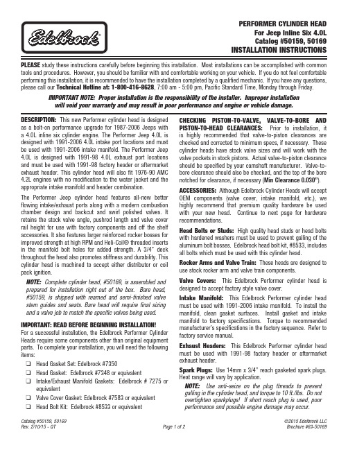
PLEASE study these instructions carefully before beginning this installation. Most installations can be accomplished with common tools and procedures. However, you should be familiar with and comfortable working on your vehicle. If you do not feel comfortable performing this installation, it is recommended to have the installation completed by a qualified mechanic. If you have any questions, please call our Technical Hotline at: 1-800-416-8628, 7:00 am - 5:00 pm, Pacific Standard Time, Monday through Friday.IMPORTANT NOTE: Proper installation is the responsibility of the installer. Improper installationwill void your warranty and may result in poor performance and engine or vehicle damage.DESCRIPTION: This new Performer cylinder head is designed as a bolt-on performance upgrade for 1987-2006 Jeeps with a 4.0L inline six cylinder engine. The Performer Jeep 4.0L is designed with 1991-2006 4.0L intake port locations and must be used with 1991-2006 intake manifold. The Performer Jeep 4.0L is designed with 1991-98 4.0L exhaust port locations and must be used with 1991-98 factory header or aftermarket exhaust header. This cylinder head will also fit 1976-90 AMC 4.2L engines with no modification to the water jacket and the appropriate intake manifold and header combination.The Performer Jeep cylinder head features all-new better flowing intake/exhaust ports along with a modern combustion chamber design and backcut and swirl polished valves. It retains the stock valve angle, pushrod length and valve cover rail height for use with factory components and off the shelf accessories. It also features larger reinforced rocker bosses for improved strength at high RPM and Heli-Coil® threaded inserts in the manifold bolt holes for added strength. A 3/4” deck throughout the head also promotes stiffness and durability. This cylinder head is machined to accept either distributor or coil pack ignition.NOTE: Complete cylinder head, #50169, is assembled and prepared for installation right out of the b ox. Bare head, #50159, is shipped with reamed and semi-finished valve stem guides and seats. Bare head will require final sizing and a valve job to match the specific valves being used. IMPORTANT: READ BEFORE BEGINNING INSTALLATION!For a successful installation, the Edelbrock Performer Cylinder Heads require some components other than original equipment parts. To complete your installation, you will need the following items:q Head Gasket Set: Edelbrock #7350q Head Gasket: Edelbrock #7348 or equivalentq Intake/Exhaust Manifold Gaskets: Edelbrock # 7275 or equivalentq Valve Cover Gasket: Edelbrock #7583 or equivalentq Head Bolt Kit: Edelbrock #8533 or equivalent CHECKING PISTON-TO-VALVE, VALVE-TO-BO R E AND PISTON-TO-HEAD CLEAR ANCES: Prior to installation, it is highly recommended that valve-to-piston clearances are checked and corrected to minimum specs, if necessary. These cylinder heads have stock valve sizes and will work with the valve pockets in stock pistons. Actual valve-to-piston clearance should be specified by your camshaft manufacturer. Valve-to-bore clearance should also be checked, and the top of the bore notched for clearance, if necessary (Min Clearance 0.030”). ACCESSORIES: Although Edelbrock Cylinder Heads will accept OEM components (valve cover, intake manifold, etc.), we highly recommend that premium quality hardware be used with your new head. Continue to next page for hardware recommendations.Head Bolts or Studs: High quality head studs or head bolts with hardened washers must be used to prevent galling of the aluminum bolt bosses. Edelbrock head bolt kit, #8533, includes all bolts which must be used with this cylinder head.Rocker Arms and Valve Train: These heads are designed to use stock rocker arm and valve train components.Valve Covers: This Edelbrock Performer cylinder head is designed to accept factory style valve cover.Intake Manifold: This Edelbrock Performer cylinder head must be used with 1991-2006 intake manifold. To install the manifold, clean gasket surfaces. Install gasket and intake manifold to factory specifications. Torque to recommended manufacturer’s specifications in the factory sequence. Refer to factory service manual.Exhaust Headers: This Edelbrock Performer cylinder head must be used with 1991-98 factory header or aftermarket exhaust header.Spark Plugs: Use 14mm x 3/4” reach gasketed spark plugs. Heat range will vary by application.NOTE: Use anti-seize on the plug threads to prevent galling in the cylinder head, and torque to 10 ft./lbs. Do not overtighten sparkplugs! If short reach plug is used, poor performance and possible engine damage may occur.INSTALLATION: Installation is the same as for original equipment cylinder heads. Consult service manual for specific procedures, if necessary. Be sure that the surface of the block and the surface of the head are thoroughly cleaned to remove any oily film before installation. Use alcohol or lacquer thinner on a lint-free rag to clean. Apply oil or suitable thread lubricant to head bolt threads and the underside of bolt heads and washers. Torque cylinder head bolts in three steps following the factory tightening sequence (See Figure 1). Edelbrock LLC • 2700 California St. • Torrance, CA 90503Tech Line: 1-800-416-8628Fig. 1 - Cylinder Head Bolt Tightening SequenceEdelbrock Cylinder Head Bolt Torque Spec(Torque specs below only apply if using ARP Ultra-Torque Fastener Assembly Lubricant; included with head ARP head bolt kits. If using other fastener lubricant(s), please use manufacturer’s recommended torque specs.)*NOTE: Make sure to use thread sealant on bolt #11 as it goes into a water jacket.First Pass: Torque all bolts, in sequence, to 25 ft./lbs.Second Pass: Torque all bolts, in sequence, to 40 ft./lbs.Final Pass: Torque all bolts, in sequence, to 80 ft./lbs..NOTES: A head bolt re-torque is recommended after initial start-up and cool-down (allow 2-3 hours foradequate cooling).SPECIFICATIONS:Head Bolt Torque:See Figure 1, or use head bolt manufacturer’s specifications Deck Thickness:3/4”Combustion Chamber Volume: 55 ±1ccValve Size (Except for 61169): Intake - 1.910” Exhaust - 1.500”Valve Seats:Hardened powdered metal, non-interlocking, compatible with unleaded fuel Valve Spring Diameter:1.265”Valve Spring Installed Height:1.720”Valve Spring Seat Pressure:**************************”Valve Spring Open PressureFlat Tappet Cam 260 lbs. @ .400” Lift Max. Valve Lift: .540”Coil Bind 1.120”Replacement Valve Springs: #5814 - Flat Tappet Cam。
中英文对照说明书
前言Preface感谢您使用徐州燃烧控制研究院有限公司生产的就地点火控制柜装置。
本公司的就地点火控制柜装置是徐州燃烧控制研究院有限公司自主开发生产的高品质就地控制装置,在使用系列本程控装置之前请您仔细阅读该手册以保证正确使用并充分发挥其优越性。
本说明书对就地控制柜(以下简称控制柜)的操作和安装方法等做了详细的介绍。
使用控制柜以前,在阅读本说明书的基础上,进行安全正确使用。
Thank you for choosing the Local Ignition Control Cabinet designed by our company.The local ignition control device is explored by our company for the ignition control of boiler.This manual describes installation and operation of the cabinet clearly, please read this manual before using.内容介绍Brief introduction本手册介绍了点火控制柜的组成、安装、配线、功能参数、日常使用维护及对故障的处理The manual includes the cabinet’s components, installation, wiring, data, maintenance, and troubleshooting.读者对象Applicable readers本书适合下列人员阅读This manual is applicable for设备安装人员、维护人员、设计人员Installer, maintenance man, and designer本书约定Stipulation符号约定Symbol stipulations说明提醒操作者需重点关注的地方Points operator should pay attention to由于没有按要求操作可能造成死亡或重伤的场合危险!This symbol indicates death or GBH that may occur as a resultof improper operation由于没有按要求操作可能造成中等程度伤害或轻伤或造成物质损害的场合注意!This symbol indicates secondary injury, flesh wound or objectdamage that may occur as a result of improper operation一、序言Prologue1.1 开箱检查Checking在开箱时请认真确认在运输中是否有破损现象控制柜内元器件与附图中的型号数量是否相符如发现有某种遗漏请速与供货商或我司联系解决!Check if there is any damage.Ensure the model and quantity in chart are accordance withcomponents in cabinet.If there is any mistake, please contact with supplier or ourcompany.1.2 安全注意事项Security不要安装在含有爆炸气体的环境里否则有引发爆炸的危险!必须由具有专业资格的人员进行配线作业否则有触电的危险!确认电源处于完全断开的情况下才能进行配线作业否则有触电危险!必须将控制柜的接地端子可靠接地否则有触电的危险!通电情况下不要用手触摸控制端子否则有触电的危险!Do not install in explosive environment, or it may causeexplosion.Do invite professionals for accompany when wiring, or it maycause electric shockDo shut off power before wiring.Do earth the cabinet ground terminal.Do not touch the control terminal when power is on.1.3 安装条件Installation Requirement1.4 日常维护Maintenance定期检查柜内各种元器件,确认任一单元都没有松动的螺钉,所有电源和电线的连接都安全可靠;并保持外观完好。
Damage Control Demonizer 说明书

Unplug unit when not is use.
-3-
LINE DRAWING AND FEATURES
Left Tube Stasis Chamber
Magic Eye Bio-Feedback Meter
FOOTSWITCHES Engage – toggles the Demonizer from TRUE BYPASS to ON. The Demonizer will pass the input signal to the output jack with no power supplied to the pedal, due to the TRUE BYPASS nature of the circuit. Nuclear – adds 20dB of gain to the Demonizer’s tube gain stages. TOP PANEL INDICATORS Magic Eye – input meter has a soothing swirling pattern and responds to the input signal level, changing its colors and patterns. Left Tube Stasis Chamber – Indicates the state of the Demonizer. The chamber glows GREEN when the pedal is in BYPASS. When ENAGAGED, the Chamber glows to match the color of the NUCLEAR state - ORANGE when NUCLEAR OFF, and RED when NUCLEAR ON. Right Tube Stasis Chamber – Indicates the state of the NUCLEAR switch. The chamber glows orange when NUCLEAR is OFF, and RED when NUCLEAR is ON BACK PANEL JACKS Input – Connect your guitar here. Amplifier Out –Connect to guitar amplifier input, or power amp input. Direct Out – Connect to console or full-range system. This output employs an advanced 14th order analog network to reproduce the sound and feel of a professionally mic’d 4x12 closed-back cabinet for direct recording. The 100% analog signal path allows a superb direct tone without sonic compromise Note that when the Demonizer is in TRUE BYPASS, no signal will appear at the Direct Out jack. Power – Connect only the supplied Damage Control AC adapter to power the Demonizer.
- 1、下载文档前请自行甄别文档内容的完整性,平台不提供额外的编辑、内容补充、找答案等附加服务。
- 2、"仅部分预览"的文档,不可在线预览部分如存在完整性等问题,可反馈申请退款(可完整预览的文档不适用该条件!)。
- 3、如文档侵犯您的权益,请联系客服反馈,我们会尽快为您处理(人工客服工作时间:9:00-18:30)。
什么样的密码有什么样的操作级别由Demag出厂时已经进行了设定。对于低级别的密码来说,一定功能的限定时为了防止未经授权或错误的操作而造成对机床和模具的损坏。
提示除了以下的功能外,其他所有页面的设置均可在一级密码下进行操作和更改。
控制页面
功能
密码等级
2
报警
“警报消除”软键
2
10
模具设置
“模厚设置”选择框
提示:机床正常运行时可通过切换到半自动模式来停机,这样比较方便。
1.2.2
一个完整的机械手(料头夹持,机械手,可放置的机械手)可以通过一下相关的按钮进行机械手的开关和相应手动动作。
Fig.7:机械手按钮
通过不断点击“单级模式”,每一序列中设置的动作都可以一步步执行,按“归位”按钮可以开始一个完整的循环。
按键发声:按键发声打开或关闭
频幕保护启动:设置时间使在最后一次操作后开始启动频幕保护。如果设置为0,则表示频幕保护关闭。
自动报警页:如果多于一个报警同时出现,则立即自动进入报警显示页面。
更改报告记录:打开更改报告记录。
在右边的“更改原因”里可以预先进行设置。然后当每次更改时,会让操作着确认更改的原因。
其他页面可通过显示频下方的软键点击进入。
Fig.2:功能选择键
1.2
在手动和点动模式下可通过下面的按钮(见Fig.3和Fig.4)进行相应的操作。
Fig.3:手动模具装置功能
提示“模厚调整”按钮只针对曲轴式机床。“自动安全门”和“气阀1-4”按钮只有当这些功能配置以后才起作用。“Rotary table latches”, Rotary table index bolt” and“旋转模板”应用于带转转模板的多色注塑。
页面的中上方显示了页面名称,页面名称下面是出错报警的显示区域。
页面名称和报警区域右边实时显示注射过程中各阶段的时间和名称。当在页面输入区域输入值时,显示了该参数的最大和最小值。
右上角是日期和时间显示。
页面的主要区域用于显示主要内容和进行参数设置。
页面下方是一些快捷软键。
页面选择
有两种方式进行页面选择:
马达功率kW /频率Hz (Drive),
主泵输出l/min (“P:“),
软件包(CPU Program,EC FirmwareandEC List)Βιβλιοθήκη 这些为售后服务提供信息。6
“83设置”页面可以通过点击“i”功能键,然后点击“设置”软键进入。
在该页面上各种各样的功能可以通过选择框(■or□)进行选择:
2.4
帮助盘可以显示EC页面,错误或报警,参数设置的相关帮助信息。可以通过点击“?”按钮激活。
专家系统可以提供参数优化和成型缺陷方面的建议;可以通过相关页面进行激活。
3
机床开启后频幕显示“0主页面”(0 MAIN MENU)(见Fig.8)
Fig.8:“0主页面”(0 MAIN MENU)
频幕设置
页面左上角显示了1到5级密码,或当未输入密码时显示地球。这也是光标的起始位置。
口令卡:选定后,操作着只能通过口令卡进行操作。
日期和时间设置:移动光标至更改区域,然后输入适当值。
单位选择:在这个区域可以对参数进行单位的更改。
外部打印机的接口COM2。
Fig.11:“83设置”(83 SETUP)页面
7
只有输入口令或插卡才可以进行参数的更改。
输入口令
输入点“.“
输入口令(最多5位) (不可见)
8.点动状态下顶动机床顶出机构,使模具顶出杆进入机床顶出孔,锁住滑块使模具顶出杆和机床顶出系统相连;然后退回顶出系统,在页面“11液压顶出”上设置顶出零位;
9.在“23注射装置”(23 Injection Unit)页面上设置射台移动速度位置以及喷嘴接触力;
10.合上模具;在点动状态下移动射台(料筒温度已达到)使其叮嘱模具浇口套,然后在“23注射装置”(23 Injection Unit)页面上设置射台零位;
内容
8
8.1
该步骤主要对那些产品或模具在Demag机床上未生产过因而没有任何工艺参数的情况提供一些指导性的建议。但具体的设置需结合具体的模具和机床来进行。
1.设置料筒各段温度,公差;打开下料口冷却水;
2.在确认好机床最小模厚,定位孔直径和顶出系统后,安装模具;
3.在“183机器设置”(183 Setup Machine)页面设置序列类型(基本序列或柔性序列);
2
11
液压顶出
所有选择框
开始位置和校验位置
2
13
模具控制直接动作
所有设置
2
14
中子
所有选择框
开始位置和校验位置
2
16
模具序列
所有设置
2
软键INIT
4
23
注射装置
“预塑前退回”选择框
“预塑后退回”选择框
2
30
温度
油温设置
5
40
预选程序
“中子”选择框
“液压顶出”选择框
PG switchAUTO mode blocked
所有的口令显示在“87口令”页面上。(见Fig.12)
该页面只有超级用户即5级密码才能进入并显示出来。
提示机器出厂时的超级密码为0
在“87口令”页面上共有50个从1到4不同级别的密码可以设置。
可通过光标进行口令位置选择和级别(1到4)的设置。密码最多为5位。
可以在超级密码区域更改超级密码。
提示:如果使用相同的密码可能会使机床遭受设置错误。
11.在“13直接控制模具动作序列”(13 Mould Direct)页面上激活“单级模式”( Step Mode),确认模具动作序列设置合理;或在“96试运行”(96 COMMISSIONING)页面激活“试循环”进行自动状态下模具动作序列的确认;
12.在“20成型工艺优化”(20 PROCESS OPTIMIZATION)页面上设置工艺参数:输入螺杆转速,背压,料量,注射速度,注射压力限定,转压点,保压时间,保压压力,冷却时间,周期监控时间,暂停时间,或转压时间等如果需要的话;
选择功能键,然后在选择频幕下方的软键;
输入要进入的页面号码;
进入“80页面显示”页面,然后通过光标进行选择。
信息光标的移可以通过选择键或旋转梭进行。(见Fig.1)
4
所有页面都显示在“80页面索引”上。(见Fig.9)
该页面可以通过点击“i”功能键或在光标起始位置输入80显示出来。
在该页面上可以通过选择键或旋转梭选择进入所有页面。也可直接通过在光标起始位置输入数值进入。
2.2
诊断盘用于机床控制程序错误诊断以及出现严重误动作时对机床进行初始化。
注意磁盘的使用必须咨询售后服务工程师。
提示:只要机床开机时,驱动盘和诊断盘在软驱内,程序就会自动启用。所以安装完毕后,必须吧驱动盘和诊断盘从软驱中拿出。
2.3
所有的工艺参数均可以存入可写入磁盘。
可使用3 ½ “高密度1.44 MB
信息字母在各手动功能键上。
1.2.1
机床有四种工作模式“点动模式”,“手动模式”,“半自动模式”,“全自动模式”(见Fig.6,从作到右)
Fig.6:模式选择键
在点动模式下,动作的速度和压力都很低,螺杆不能动作;在手动模式下,手动点击各动作时,机床按页面上设置的参数进行动作;在半自动模式下,机床按设定的参数工作一个循环后,停止在模具打开的状态;在全自动模式下,机床按设定的参数进行循环工作。
4.在“16模具动作序列”(16 Mould Sequence)页面上设置模具和顶出序列
5.在“10模具设置”(16Mould Setting)页面上设置模具开合模速度,位置,模保力,锁模力等
6.在点动状态下合模直到模具合上,设置模厚(注意直压式和曲轴式合模机构的区别),然后打开模具;
7.选择“11液压顶出”(11 HydraulicEjector)页面进行顶出速度,位置和压力的设置;
Fig.12:“87口令“(87 PASSWORD)页面
7.1
口令卡可以在“87口令“页面进行级别设置(见Fig.13)
该页面只有超级用户即5级密码或口令卡才能进入并显示出来。
信息:初始口令卡的级别为5级,口令为0
插入口令卡
点击用户卡
在用户卡区域输入密码
在口令级别区域输入级别
点击储存到卡
Fig.13:“87口令“(87 PASSWORD)页面进行口令卡的设置
2
机床的控制程序存储再磁盘中。
提示:所有的磁盘可以(也应该)在电脑力备份。原始盘应存放在安全位置。
2.1
如果控制程序因为某种原因而损坏,必须重新安装驱动盘(“SPS” (machine PLC), “EC pages” and “EC firmware”)。如果机床作了某些功能更改,则“SPS源”程序也必须重新安装。
Fig.4:注射装置的手动功能键
提示注射装置2只用于多色注塑。
Fig.5:特殊手动功能键
提示:特殊功能键根据客户需求。他们的要求会在机床操作手册内显示出来。
点击打印按钮可直接打印显示频当前页面,或通过外接打印机打印。
提示:帮助功能是选配功能。需要额外的磁盘。
控制版面中带有外接端口程序页面(如:“输入”,“输出”)和自由编写页面。当需要输写时,光标必须移到书写区域,然后点击“ABC”按钮。
5频幕20
频幕设置20
页面选择21
6页面显示(索引)22
7机器(配置)23
8基本设置24
9操作进入25
输入密码(允许可更改的输入)25
取消密码(取消输入)25
9.1密码设置页面26
9.2磁卡设置27
9.3密码等级28
1
Fig.1:Ergocontrol NC4控制版面