移动电源说明书翻译
数码移动电源使用说明书
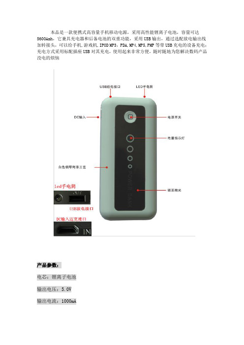
本品是一款便携式高容量手机移动电源,采用高性能锂离子电池,容量可达5600Amh,它兼具充电器和后备电池的双重功能,采用USB输出,通过选配放电输出线加转接头,可以给手机,游戏机,IPOD MP3,PDA,MP4,MP5,PMP等带USB充电的设备充电;充电方式采用标配插座USB对其充电,使用起来非常方便,随时随地为您解决数码产品没电的烦恼产品参数:电芯:锂离子电池输出电压:5.0V输出电流:1000mA输入电压:5.0V输入电流:1000mA容量:5600mAh充电时间:5-6.5小时(根据电池所“盛”电量)运行时间:5小时左右(依据市场上不同品牌,型号和操作模式而定)循环寿命:>400次工作温度:-10℃-40℃储存,运输温度:-20℃-50℃体积:90*57*20mm重量:120克携带方式:放在口袋,旅行背包,电脑包里或放在车里等电量显示:四灯指示,按下电源健,指示灯根据电量显示,第一(最大)指示灯表示剩余电量约为100%--75%,第二指示灯75%--50%,第三指示灯50%--25--%,第四指示灯25%--0。
给本移动电源充电显示:充电时从第四灯到第一灯按顺序亮,四灯都亮表示充电到100%充电方法:使用原装的电源适配器加上标配的充电转接头对本产品直接充电适用设备:适用于所有带USB充电的设备使用,如手机,PSP,IPOD,MP3,MP4,PMP,GPS,蓝牙,数码相机等。
思展宏都可以兼容3个数码充电接口一般都是常用型接口迈克接口迷你接口和iphone,ipad专用接口注意事项1.首先请检查被充电设备是否和该产品电压相兼容2.首次使用请确保产品充电时间为8小时以上3.请勿将输出电压调整到高于设备电压,否则有可能引起设备损坏,请在使用前一定确认清楚4.请使用指定充电器5.禁止短路,分解和抛入火中6.不得擅自拆卸充电器和电池对其进行改造7.注意防潮防水声明:擅自拆开产品,人为损坏,和超过保修期的产品,不在免费保修范围内。
移动电源说明(中英)

规格说明1.容量:5200mAh2.输出电压:DC 5V3.输出电流:1000mA4.输入电压:DC 5.3V5.输入电流:1000mA操作1.按开关一下F 显示电量2.按开关两下F LED灯开3.按开关两下F LED等关4.插上USB按一下F电压输出5.充电指示当电量充满一格长亮二格灯闪当电量充满二格长亮三格灯闪当电量充满三格长亮四格灯闪当电量充满四格长亮充电结束6.放电指示当轻按开关电量显示四格当电量小于一格时再放电电量灯闪代表电量不足Specification1. capacity:5200mAh2. output voltage:DC 5V3. output current:1000mA4. input voltage:DC5.3V5. input current:1000mA1. Press the power switch F to indicate the battery level.2. Press the power switch F two times, the LED light on.3. Press the power switch F two times again, the LED light off.4. This Case can be charged by connected with the iPhone USB port. 5.Indication of chargingPress Switch F, one indicator light indicates 25% of the battery level;two indicator lights indicates 50%;three lights indicates 75%,and four lights indicates the case has been full charged.7.Indication of dischargingWhen the indicator light less than one the battery case is not enough power to use, you should charge it.。
AA胶电池可移动电源产品说明书

Energy Management System Operation ManualPlease read this manual before attempting to install or operate any of theEMS system components. AA Portable Power Corp. will not be responsiblefor any problem due to misusing.Catalogue1Introduction: (3)2Specification (3)3Typical diagram: (4)4Heart Beat LED (5)5Isolate Battery & Shunt connection: (6)612V Power: (6)7Monitor Page select switch: (7)8Sense Board Wiring: (7)9Battery balancing (9)10Video Output (10)11Can Bus Output (Optional) (10)12Main Screen: (11)13Individual Cell Page (12)14Alarms: (13)15Controlling Devices with Alarm Outputs (14)16Capacity Algorithm (14)17Ground Fault Detection (15)18Trouble Shooting (16)1Introduction:Thank you for purchasing Energy Management System (EMS). This manual covers the operating and installation information for this systemThe EMS system has everything needed to display the condition and maintain the health of lithium ion batteries and is specifically designed to work with GBS Lithium Ion batteries.The system consists of two major components, the computer Master (MASTER) and the cell sense boards. The MASTER shows details about the condition of the battery pack, such as current, voltage, state of charge and individual cell details, via its video output display. The sense boards form a simple daisy chain by mounting on each cell to read voltage and temperature; they also perform battery balancing during recharging to equalize the charge within the battery pack. Two alarm outputs, one for over voltage and one for under voltage, provide automatic shut off signals to prevent overcharging or over discharging of the battery pack. A unique feature of the EMS system is ground fault detection. High voltage systems should be floating relative to the chassis for safety. If an inadvertent path to the chassis ground is made the system will detect it and display a warning for this unsafe condition. The EMS outputs composite video to display battery pack information. A CAN (controller area network) interface option is available to output the information from the EMS to other systems.2Specificationoutputs3Typical diagram:The EMS is designed to make installation as easy as possible. All of the connections to it are made with convenient pluggable ¼” quick disconnect terminals. The EMS Master should be installed as close to the shunt as possible. The shunt sense wires should be less than 1’ long. A mounting template for the computer is shown in Appendix A. After the installation is complete, the battery pack must be completely charged before the capacity will read correctly (see Section 7.Capacity Algorithm for more details).Note: The EMS system components utilize either a conformal coating or rubberized coating on all components to allow them to perform in high humidity environments. They are not however water proof. All components must be installed inside water resistant containers.4Heart Beat LEDWhen the EMS is correctly connected to 12V, the heartbeat indicator will blink once per second5Isolate Battery & Shunt connection:The Terminals on the left side of the Master are used for making the High-Voltage and shunt connections. Refer to the figure below for these connections. The connections between the battery pack, shunt and high voltage loads are usually large wire (e.g. 2/0 depending on the max current of the system).The connections to the EMS from the battery and the shunt can be smaller gauge (e.g. 18 or 20 Awg).Note: Please use extreme caution when making these connections as the full battery pack potential will be present between the shunt and battery pack positive pins. Connecting these wires incorrectly can cause damage to the EMS MASTER which will not be covered under warranty.The wires connecting to the shunt should be a twisted pair or wires with as short of a distance from the MASTER as possible to achieve accurate measurements.612V Power:The MASTER is powered by 12 volt s, which is connected to the terminals marked “12V”and “GND”. This should be connected to a power source through a 5A fuse. The power can either be always on, or can be switched off to conserve power. 12 volt power must besupplied at any time when the battery pack is being charged or discharged. When 12 volt power is applied the red heartbeat LED will blink.If the battery pack is more than a 12 volt battery, and the MASTER is to be powered off of it,a DC/DC converter must be used so that the battery pack is discharged equally. Under nocircumstances can four cells within the battery pack be tapped for 12 volt power for the MASTER as this will cause an imbalance within the battery pack.Note: T here are three pins marked “GND” for ground on the MASTER. These three pins are common together. Only one of these pins needs to be connected, the other two are located for convenient connection options. It is not chassis.7Monitor Page select switch:To change the display on the MASTER to the individual cell screen(s) a normally open momentary switch is used to short the pins marked (MDE) to (GND). There is no polarity to the switch and the connection can be small gauge wire (e.g. 18 Awg). In applications where the 12 volt power is grounded to a vehicle chassis only one wire needs to be ran from the MDE pin and can be grounded to the chassis through the momentary switch.8Sense Board Wiring:The sense boards are connected to the MASTER via a cable with five pins. Depending on which sense board version the system was supplied with this cable will have either four or five wires connected to it. This connector has a retention mechanism. If removal of this cable is needed never pull in the wires, always pull up on the connector, to avoid damage to the wire harnessThe MASTER will automatically index the sense boards based on their position in the daisy chain of sense boards. The first sense board connected to the MASTER will be cell number one and will count up from there. It is recommended that the negative most cell in the pack be made cell number one and have the daisy chain move toward the most positive cell in the pack. This will aide in troubleshooting if needed; however, the sense boards can be connected in any order.Before installing sense boards, install all cell jumpers first with the outer two screws tightened. Never install sense boards underneath jumpers as this will cause current to flow through the screws, which is a poor connection. Never slide a jumper underneath a sense board while installing as this may cause a short with components which are located on the back of the sense board.When installing sense boards, keep cell covers installed on all cells except the cell where the sense board is being installed. Do not allow sense boards to lie on battery terminals. This will help prevent accidental damage to sense boards during installation.The sense boards have an input and an output connector. Before installing, ensure that they are oriented in the appropriate direction. The male connector is the input; the female connector is the output.The sense boards have battery positive and negative indicated on them. Ensure that the polarity is correct before installing. The boards will not be damaged by a reverse polarity; however, they will not function. When a sense board is installed correctly the green LED will light up. There is also a red LED on the sense board, which indicates cell balancing is occurring.This led will light up any time the cell voltage is 3.55V or higher.Note: The sense boards, like the cells they attach to, alternate + and – for the series connection. The last string in the daisy chain is not terminated and will have its output connector not connected to anything. Should the installation have less than an even multiple of 4 cells, the cable may be cut close to the last sense board used. Be sure to cut the cable cleanly with no wires left exposed. Do not cut the cable with 12V power applied to the MASTER! The resulting short circuit may damage the EMS computer.9Battery balancingWhen the battery voltage rises during charging to 3.55V or above the red balancing LED will light on the sense board to indicate the cell is balancing. The sense boards will draw 0.5A until the voltage has dropped below 3.55V. It is normal for some cells to balancemore than others and some cells to rarely balance.10 Video OutputThe EMS MASTER outputs composite video output through a common RCA type jack. This can be connected to the optional LCD screen EPS provides or any other display which will accept this type of input (e.g. in dash DVD). The video cable is not provided as length requirements vary. A shielded cable is recommended if there is snow or static in the video signal11 Can Bus Output (Optional)If your MASTER has the optional CAN bus interface this connector will be on the side of the MASTER.12 Main Screen:When properly installed, the EMS system will display the Voltage, current, capacity and alarm status of a Lithium Ion battery pack. This is an example of what the main screendisplays:Number of Cells is indicated at the top of the screen as “E.M.S –x” where x is the number of sense boards the MASTER has been programmed to manage. If the system detects a value other than this it will trigger an unmanaged cell alarm.Battery Pack Voltage is the total battery pack voltage. This updates in real time and the numerical value is displayed below the bar. This bar will be green whenever voltage is between 3.0V x N (the number of cells in the pack). When the voltage drops below 3.0V x N the bar will turn red to indicate low voltage. The bar will also turn red when the voltage rises over 3.4V x N to indicate that the target charging voltage range has been attained. If the voltage goes outside of the range of the bar and off scale message will appear.Battery Pack Current is the current either being drawn from the battery or being recharged into it. Like the voltage bar this is indicated in real time and the numerical value is displayed below the bar. This bar will be green and will turn red when current is above 200A. When current is negative and the battery is being charged this bar will turn white and “Charging” will be displayed.Battery Pack Capacity is the battery state of charge. It works by tracking the amount of charge that goes in and out of the battery pack. It will reset to 100% during charging when the current is within a normal charging range for a battery charger and the total battery pack voltage reaches 3.52 x N (the number of cells). When the system is powered up for the first time this value will read 50%. The battery will have to be charged to full in order to reset the capacity reading correctly to 100% the first time.Min/Max Cell Voltage provides a quick overview of the maximum and minimum cell voltages within the battery pack. Depending on the number of cells within the battery pack, these values update every 1 -2 seconds.Alarms and Warnings are displayed at the bottom of the screen after the word “Pack:”.There are seven alarms:- Over voltage (highest cell is over 3.8V after a 3 second delay)- Under voltage (lowest cell is below 2.8V after a 30 second delay)- Over current (current exceeds 10C for 10 seconds)- Over temperature (highest cell exceeds 150°F or 65°C)- Under temperature (lowest cell is below 32°F or 0°C, charging is not allowed)- Ground fault (There is a high voltage leakage greater than 2mA to the chassis pin)- Unmanaged cells (The programmed number of cells does not equal the number of cells read)13Individual Cell PageTo access the individual cell detail page(s) refer to section 7, Page Select Switch Input.When momentary switch is pressed and released it will change the display to show the first20 cells in the pack with details of voltage and temperature of each cell as shown below:If there are more than 20 cells in the pack pressing the button again will advance tothe next 20 cells until the last cell page is reached, then pressing the button againwill return to the main screen.Cell (number) is the location of the sense board relative to the daisy chain of sense boards. The cell connected to the MASTER first is number one.Volts is the actual cell voltage. This updates every 1-2 seconds, depending onthe number of cells in the pack.Temp is the temperature reading. This updates every 1-2 seconds, depending on the number of cells in the pack. The number will turn red if the cell exceeds the upper temperature limit. Readings are in °F by default; however, upon request, this can be set to read in °C.The cell temperature is measured at the positive terminal of each sense board. If a single cell has noticeably higher temperature during use than other cells, but the temperature goes back down quickly this may be an indication of a poor connection where there is high contact impedance. Also, during balancing the temperature will temporarily rise due to the energy being converted to heat.Note that this screen will not automatically update if more or less cells are connected during installation. To update the screen the Page Select buttonmust be pressed until it has cycled back through the main screen, then back tothe individual cell detail screens in order to update the view. Cell voltage and temperatures are updated in real time on these screens.14Alarms:In order to protect the battery pack there are a number of alarms, which are based on cell voltage, temperature and pack current and fault conditions. The MASTER contains two alarm output pins, UV for under voltage and OV for over voltage. When any of the alarm conditions are met for a specified duration of time they will activate their respective action listed in the table below:The alarm limit values may vary with special request configurations.The same delay time must elapse once an alarm condition is cleared to deactivatethe alarm.15Controlling Devices with Alarm OutputsThe alarm outputs on the MASTER output 12 volts and can drive continuously 2A with up to a 4A surge. Exceeding these limits or short circuiting these pins may cause damage to the MASTER. The alarms act according to the above table. It is very important that these alarm outputs be able to disconnect the battery pack from loads and charging sources when they activate; this must be a no parasitic load condition to fully protect the battery. Ensure that items such as controller pre- charge resistors, DC/DC converters, lights, etc. are all disconnected in the event that the low voltage alarm triggers. Failure to properly implement these alarm interlocks may void the warranty on the battery.When all parameters are within normal ranges these alarm outputs will be 12 volts. They will drop to 0 volts during an alarm condition. When power to the MASTER is removed these outputs will not supply power. Systems should be designed such that they require power from the alarm outputs from the MASTER in order to function.16Capacity AlgorithmThe EMS MASTER keeps track of the capacity of the battery pack by tracking current in and out of the battery (coulomb counting). There are however several corrections built in to the software to ensure that the capacity stays accurate over time.The capacity will reset to 100% if the following conditions are met:- Total pack voltage measures 3.52V x N (N being the number of cells) when being charged by a battery charger.The capacity will reset to 100% if the following conditions are met:- The over voltage alarm is triggered when being charged by a battery charger, see default alarm table for set points.The capacity will reset to 0% if the following conditions are met:- The under voltage alarm is triggered and discharging current is not excessive, see default alarm table for set points.When the EMS is powered up the first time the capacity will read 50%, which is approximately the state of charge that the batteries ship at when new. To sync the capacity the first time the battery pack must be charged full, which will trigger a reset to 100%.The capacity measurement is done based on the programming in the MASTER. MASTER’s cannot be interchanged with one which has been programmed for a different battery pack configuration.Upon special request the MASTER can be programmed to extend battery life by limiting the depth of discharge to 80%. This will scale the capacity bar such that 100% of the scale is 80% of the battery capacity. Once the capacity reaches 0%, which is 20% of the actual capacity remaining, the under voltage (UV) output will automatically shut off.17Ground Fault DetectionThe pin marked “Chassis” is used for the ground fault detection circuitry integrated in to the EMS MASTER. This should be connected to its own dedicated chassisground point. When this is done and the shunt and battery positive wires areconnected properly the system will be able to detect a ground fault anywhere within the battery pack. This feature will display an alarm message on the screen if there is a fault condition, but will not cause any alarm actions to be taken. If this message appears there is a potentially dangerous ground fault condition which should be corrected.The alarm will be triggered any time a current of 2mA or greater is detected from the battery pack to the chassis pin.If the EMS system is being used on a lower voltage system (<50 volts) where the battery pack is grounded to the chassis, this wire should not be installed to disable this feature. EPS does not recommend grounding battery packs in excess of 12 cells in series for safety.When performing work on a high voltage battery pack, the Chassis pin should temporarily be disconnected as it will induce a very small, non-dangerous, current to the chassis which could cause small electrical shocks.18Trouble ShootingA sense board is reporting a temperature above the spec limit and is shutting down the system to protect the batteryCheck for loose connectionsA sense board is reporting a temperature below the spec limit for charging and has shut off charging equipment to protect the battery packA potentially dangerous leakage current to the chassis has occurred. Find the source of this leakage and remove it.For low voltage systems where the battery pack is grounded to the chassis disconnect this pin to eliminate this feature.。
wopow沃品4400mAh安心移动电源PD001使用说明

型号:PD001用户手册DC 5V 本产品适用于-输入的电子数码产品充电00mAh安心 移动电源 44Wopow ○R Safety Portable Power Supply 4400 mAhUser ManualModel Number: PD001This product is used for Charging DC-5V input Electronic Digital Product一、产品简介ⅠProduct Introduction:本产品为移动备用电源。
输入端为Micro 5pin USB 接口,内置进口三星18650可充电锂电池,总容量为4400mAh ,充电电流为1000mA Max ;输出端为标准 2.0 USB 接口,输出规格为5V 1000mA Max 恒压限流。
This product is portable backup power supply. Input termianl is Micro 5pin USB interface, built-in imported Samsung 18650 rechargeable Lithium battery, total capacity is 4400mAh, charge current is 1000mA Max; output terminal is Standard 2.0 USB interface. Output standard: 5V/1000mA Max, constant-voltage & limitary-current可随时随地对您的IPAD 、IPHONE 、MP3、MP4等数码产品进行充电,解决无电的烦恼。
使用前请仔细阅读说明书。
Charging your IPAD 、IPHONE 、MP3、MP4 and other digital products at any time and any place, to solve the power-off trouble. Please read the instruction carefully before usage二、部件识别ⅡStructure of componentsUSB 输出小电筒4档电量1. 4 level indicator light2. Power Indicator Light button3. LED flashlight4. USB output interface5. Micro Input Interface三、使用说明Ⅲ Usage instruction1.LED 小电筒使用:长按按键2秒,LED 小电筒打开;再长按按键2秒, LED 小电筒关闭.满电状态,使用LED 小电筒照明可长达100H 以上。
移动电源说明书翻译
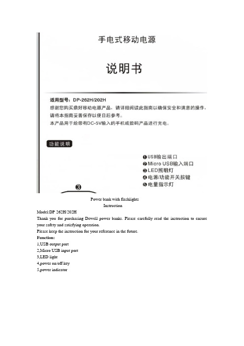
Power bank with flashlightsInstructionModel:DP-262H/202HThank you for purchasing Dewell power banks. Please carefully read the instruction to ensure your safety and satisfying operation.Please keep the instruction for your reference in the future.Function:1,USB output port2,Micro USB input port3,LED light4,power on/off key5,power indicatorTechnical specificationName : power bank with flashlightModel: DP-262H/DP-202HInput: 5V-1000mAOutput: USB5V-1000mAVolume: 105*47*31mmWeight: 156gCapacity range: 2600mAh*2/2000mAh*2Temperature range:Time to fully charge the cell: It costs 10 hours when in 5V--0.5AIt costs 8 hours when in 5V--1ARemark:1,Because of the conversion rate of the power bank, the real capacity of the power bank isn’t equal to the charging capacity.2, The specification and outer appearance of our product can change at anytime because of improvement.3, Power bank with flashlight all uses high capacity Li-ion cell, you can safely use it with its high quality.Instruction1,Please use the USB cable and charger that matches your phone or other digital products. (Remark: If you don’t use the cable or charger as the instruction indicated, we won’t take the responsibility for any possible deletion of the telephony information store, when you are using our power bank with flashlight.)2, To ensure the stability, please use the standard 5V1A charger.3, This product use Micro USb input port to charge itself and use the USB output port to charge the devices that is connected to the product.4,Electric energy will be consumed during charging/discharging. Slight heating is normal.5,Please store the product in a cool and day place. If it is not to be used in a long time, please fully charge the power bank once every six months.6,One Micro USB cable is attached inside. I t can charge oover 95%of the phones in the market. (Note: some products are not applicable.)Output interface Output current Applicable devices USB 1A Most mobile phones includingSamsung,HTC,Huawei,ZTE,Nokia, MOTO and full-seriesApple devices like iPhone,iPadand iPod or devices requringDC 5V o.5A-1A input.(Note:Samsung PPC and certainSamsung models requireexternal adapters beforeconnecting.)Instruction:1,Charge your power bankUse Micro USB cable to charge your power bank with flashlightUse computer to charge the power bank with flashlight 2 Charge your electronic devicesUse power bank with flashlight to charge your phoneUse power bank with flashlight to charge your tablet PC.Charge and discharge instructionFirst, Charge the built in battery of the power bank1,When the built in battery power is less than 25%, one of the light on the LED will flash, while the other three are still closed.2,25%《battery power <50%, the first light of the LED will open, while the second light will flash, and the rest remain closed.3,50%《battery power<70%;the first and the second light will open ,while the third will flash,and the rest remain closed.4,75%《battery power; the first three lights will open, the forth light will flash.5, when the built in battery is fully charged, all of the LED lights will open. Please stop charging.If in the course of charging, you connect your phone or digital products ,it will first charge your devices and the all of the LED lights will open. When your devices are fully charged, it will charge for the power bank itself and the LED lights display the built in battery power.Second, when in standby, the power bank will be in sleeping mode. When you connect your phone or digital products, the USB will automatically recognize and output. At this time, the power bank can charge your phone or digital products and the LED lights will display the rest power of the power bank.1, the rest power》75% , three of the LED lights will open, and the forth will flash.2,50%《the rest power<75%, two of the LED lights will open,while the third will flash, and the forth is closed.3,25%《the rest power<50%, the first LED light will open, while the second flashes and the rest are closed.4, the rest power<25%, the first LED light will flash, and the rest are closed.5, When all of the power are off, all the LED lights are closed and stop charging.(Note: The above number are only for you to refer)LED flashlight function instructionA, When in standby mode, long press the LED flashlight switch for 2 seconds, it will enter into strong light mode.1,press the button again,it will enter into flash exposure mode.2,Press the button again, it will enter into SOS mode.3,press the button again, the LED flashlight will close.B When the LED flashlight is at work, long pressing the switch button can directly close the LED flashlight.Customer service informationAbove are the malfunction and methods to resolve the malfunction. If the above operation can not resolve the product malfunction, please stop using the product immediately and contact the distributor or the Dewell official customer service line.TroubleshootingWhen the power bank malfunctions for some reason, you can resolve the malfuctions yourself. Fault content Failure prediction Trouble shootingCharging indicator Unqualified or incompatiblecharger is used for chargingPlease choose qualified,qualityassurance chargerMicro/USB input interfacepoor contact USB outputinterfacePlease check whether theinput/output interface is ingood connection Unqualified or incompatiblecable is used for chargingPlease use the attached ororiginal cableCharging is not automatically identified Built-in circuit protectiondosen’t match the active cable1,please original cable tocharge.2,first connect the power bankthen connect the phoneheat The battery itself will slightlyheat up when at work Please pay attention to whether the power bank is working at normal environmentThe lifetime of the power bank is too short The service life of the battery isto endPlease replace the power bank,if it cannot work any more.Precautions*please keep the product in a cool and dry place*please do not touch the product when your body is wet.*please don’t place the product in high temperature or high humidity or exposure to direct sunlight.*Please don’t place the product on the carpet, heater, fabrics or expose it in the direct sunlight. *Please keep the charging temperature around .*Please do not put the product on combustible material*It may explode if you remove or disassemble the built in battery.*Please do not put the product in the fire, river or corrosive liquid.*Please do not smash, squeeze of disassemble the product yourself.*If the product is found to have swelling or other malfunctions, please immediately stop using it and contact your dealer.*Unless there are professionals supervising or instructing, the following people are not supposed to use the product: people in degradation of mind or body, people who know little about the product. Please supervise children to ensure safety.Guarantee cardWarranty period:12months (it starts when the day you buy the product)Free service:During the warranty period, for all malfunction caused by the quality of the product itself, the customer can contact the dealer and enjoy free repair.The following situations cannot enjoy free repair:1,Damage caused by dis-assembly of yourself2,No guarantee card or the label has been damaged3,Damage caused by force majeure4,Damage caused by falling into water or man-made mechanical damageCustomer nameaddressProduct modeldealerTel:Product namePurchasing date。
mophie 移动电源 powerstation 使用说明书

WelcomeThank you for purchasing the mophie powerstation mini, powerstation, powerstation XL or powerstation XXL battery. Your powerstation battery is a compact yet powerful mobile charging solution for your tablet, smartphone, wearables and other USB devices. Now you will be able to travel great distances and be the master of your own destiny, no longer bound by the limitations of your device’s internal battery! Package Contains• powerstation mini, powerstation, powerstation XL or powerstation XXL portable battery• USB-A to USB-C cable• Quick-start guideFeaturesHere’s a rundown of why your powerstation mini, powerstation, powerstation XL or powerstation XXL battery is so great:• High-density, high-output portable battery charges devices at fast speeds—up to 3 ampsvia the USB-C port (up to 2.4 amps for thepowerstation mini).• Additional USB-A output ports let you charge multiple devices at the same time.• USB-C input/output port recharges the portable battery at fast speeds—up to 3A with acompatible wall adapter (up to 2.4 amps for thepowerstation mini).• Track battery power at a glance with the integrated four-light LED status indicator. Youcan keep tabs on charging status and currentbattery life. Know before you go!• mophie’s smart adaptive charging technology identifies your connected device and alwaysdelivers the fastest, most efficient chargingspeeds available.• Digital Power Management circuitry provides built-in short-circuit, overcharge and temperatureprotection. Safety first!CompatibilityThe mophie powerstation mini, powerstation, powerstation XL and powerstation XXL batteries are designed to work with most popular USB devices and wearables.• If you experience any issues with charging your device, ensure that the powerstation batteryis fully charged and check the FAQ section onthis website.No matter what device you have, carefully read through the Warning section in this manual and in the quick-start guide included with your battery before using it.Charging your powerstation battery IMPORTANT: Before using your powerstation mini, powerstation, powerstation XL or powerstation XXL battery for the first time, fully charge it (so that pressing the charge status button lights all four status LEDs).To charge your battery, use the supplied cable to connect the battery’s USB-C input/output port to a power source with a USB output, such as the wall adapter included with your smartphone or other device.powerstation mini;powerstation:powerstation XL;XXL:powerstationCharging your deviceConnect the cable that came with your device to one of the powerstation mini, powerstation, powerstation XL or powerstation XXL battery’s ports and to your device. All of the battery’s ports are available simultaneously, so you can charge multiple devices at the same time. Press the status button for 3 seconds to begin charging.powerstation mini;powerstation:If you have USB-C devices, connect them to the powerstation, powerstation XL or powerstation XXL battery’s USB-C connector for faster charging (up to 3 amps).Priority+ chargingWhen you’re recharging your powerstation mini, powerstation, powerstation XL or powerstation XXLpowerstation XL; powerstationXXL:battery, Priority+ charging provides power to a connected device first before the battery starts to recharge. Priority+ charging is available at the USB-A port that is marked with the following icon:powerstation mini; powerstation :powerstation XL; powerstation XXL:Checking your battery’s charging statusPress the status button on your powerstation mini, powerstation, powerstation XL or powerstation XXL battery and the status LEDs will indicate its charge level. Four LEDs means that the battery is fully charged, while one LED means that it’s almost empty. Know before you go!Taking care of your powerstation battery• Keep your battery dry and away from moisture and corrosive materials.• Do not clean your battery with harsh chemicals, soaps or detergents. Just wipe the case with asoft, water-dampened cloth.• Make sure the battery’s charging ports do not become contaminated with lint or other debris.Use a canned-air type of product periodically toensure that the port openings are clear.• Recharge your battery once every three months when not in use. If you plan on putting it away,fully charge it first (so that pressing the statusbutton lights all four charge status LEDs). WarrantyAt mophie, we are dedicated to making the best quality products. To back this up, this product is warranted for 2 years. For full details regarding warranty terms and exclusions, please visit: /warranty. This warranty does not affect any statutory rights that you may be entitled to. Keep a copy of your purchase receipt as proof of purchase. Be sure to register your product at .Exclusions & LimitationsExcept for the limited warranty expressly set forth or to the extent restricted or prohibited by applicable law, mophie expressly disclaims any and all other warranties express or implied, including any warranty of quality, merchantability, or fitness for a particular purpose, and you specifically agree that mophie shall not be liable for any special, incidental, indirect, punitive, or consequential damages for breach of any warranty of any type on any mophie product. In addition to and without limiting the generality of the foregoing disclaimers, the limited warranty does not, under any circumstances, cover the replacement or cost of any electronic deviceor personal property inside or outside of the mophie product.You may have additional warranty rights depending on your country, state, or province. Further, some countries, states, and provinces do not allow the exclusion or limitation of incidental or consequential damages or exclusions or limitations on the duration of implied warranties, so the above may not apply to you. If any provision of the warranty is found unlawful, void, or unenforceable, that provision shall be deemed severable and shall not affect any remaining provision.Customer ServiceTelephone: 1-888-8mophie (1-888-866-7443) International: +1 (269) 743-1340Web: /csIMPORTANT SAFETY INSTRUCTIONSWarningRead all instructions and warnings prior to using this product. Improper use of this product may result in product damage, excess heat, toxic fumes, fire or explosion, for which damages you (“Purchaser”), and not mophie llc (“Manufacturer”) are responsible.N Before using your powerstation battery for the first time, fully charge it (so that pressing thecharge status button lights all 4 status LEDs).N Do not store device in high-temperature environment, including heat caused by intense sunlight or other forms of heat. Do notplace device in fire or other excessively hotenvironments. Exposure to fire or temperatureabove 212°F (100°C) may cause explosion.N This product should be operated only in open-air conditions. It should not be operated in anenclosed, unventilated space such as a carryingbag, pocket, purse or bedding. Failure to followthese instructions may damage the productby overheating.N Be cautious of drops, bumps, abrasions, or other impacts to this product. If there is any damageto the product such as dents, punctures, tears,deformities, or corrosion due to any cause,discontinue use. Contact Manufacturer or dispose of it in an appropriate manner at yourlocal battery-recycling center.N Do not expose the portable battery to rain or snow.N Do not use the portable battery in excess of its output rating. Overloading outputs aboverating may result in a risk of fire or injuryto persons.N Do not disassemble this product or attempt to re-purpose or modify it in any manner.N Do not attempt to replace any part of this device. N For questions or instructions for the various ways to charge this device, refer to the Charging yourpowerstation battery section of this user manual. N Use of a power supply or charger not recommended by mophie may result in a risk offire or injury to persons.N If this device is accessible to or may be used by a minor, purchasing adult agrees to besolely responsible for providing supervision,instruction, and warnings. Purchaser agreesto defend, indemnify, and hold Manufacturerharmless for any claims or damages arisingfrom unintended use or misuse by a minor.N All products have gone through a thorough quality assurance inspection. If you find thatyour device is excessively hot, is emitting odor,is deformed, abraded, cut, or is experiencingor demonstrating an abnormal phenomenon,immediately stop all product use and contact Manufacturer.N Never dispose of batteries in the garbage.Disposal of batteries in the garbage is unlawfulunder state and federal environmental laws andregulations. Always take used batteries to yourlocal battery-recycling center.N Switch off the portable battery when not in use.The portable battery will automatically switchoff when disconnected from a device.LegalThis product is meant for use only in conjunction with the appropriate device. Please consult your device packaging to determine whether this product is compatible with your particular device. Manufacturer is not responsible for any damages to any device incurred through the use of this product. Manufacturer shall not in any way be liable to you or to any third party for any damages you or any third party may suffer as a result of use, intended or unintended, or misuse of this product in conjunction with any device or accessory other than the appropriate device for which this product is designed. Manufacturer will not be responsible for any damages you or any third party may suffer as a result of misuse of this product as outlined above. If you are responsible for product use with an unintended device and damages result from such use, you agree to indemnify Manufacturer for any resulting injuries to any third part(ies).mophie, powerstation, Priority+, Stay Powerful, mophie loves you, the five-circles design, and the mophie logo are trademarks of mophie inc.Lightning is a trademark of Apple Inc. USB-C is a trademark of USB Implementers Forum. All rights reserved. Patents: /patents.This device complies with part 15 of the FCC Rules and RSS-Gen of IC Rules. Operation is subject to the following two conditions: (1) This device may not cause harmful interference, and (2) this device must accept any interference received, including interference that may cause undesired operation. NOTE: This equipment has been tested and found to comply with the limits for a Class B digital device, pursuant to part 15 of the FCC Rules. These limits are designed to provide reasonable protection against harmful interference in a residential installation. This equipment generates, uses, and can radiate radio frequency energy and, if not installed and used in accordance with the instructions, may cause harmful interference to radio communications. However, there is no guarantee that interference will not occur in a particular installation.If this equipment does cause harmful interference to radio or television reception, which can be determined by turning the equipment off and on, the user is encouraged to try to correct the interference by one or more of the following measures:• Reorient or relocate the receiving antenna.• Increase the separation between the equipment and receiver.• Connect the equipment into an outlet on a circuit different from that to which the receiveris connected.• Consult the dealer or an experienced technician for help.CAUTION: To comply with the limits of the Class B digital device, pursuant to Part 15 of the FCC Rules, this device must be used with certified peripherals and shielded cables. All peripherals must be shielded and grounded. Operation with non-certified peripherals or non-shielded cables may result in interference to radio or reception. MODIFICATION: Any changes or modifications of this device could void the warranty.WEEE DECLARATION:All of our products are marked with the WEEE symbol; this indicates that this product must NOT be disposed of with other waste. Instead it is the user’s responsibility to dispose of their waste electricaland electronic equipment by handing it over to an approved re-processor, or by returning it to mophie, inc. for reprocessing. For more information about where you can send your waste equipment for recycling, please contact mophie, inc. or one of your local distributors.THIS DEVICE CONFORMS TO UL STD. 60950-1. CERTIFIED TO CSA STD. C22.2 NO. 60950-1. CONFORMS TO UL SUBJECT STD. 2056.。
SP-007S黑白充电宝摄像机、高清1080P移动电源摄像机中文操作说明书

感谢您购买移动电源摄像机(以下简称为移动电源)说明:●移动电源的功能与外观以购买的产品为准,图片仅供参考。
产品选择的详细信息,请咨询您的零售商。
●本手册介绍了移动电源的基本操作,对本产品软件方面的配置操作,请参见软件配置或者联系零售商获得帮助信息。
●当移动电源在充电或者长时间使用时,由于封闭空间不利于散热,会出现温度升高,移动电源发热的现象。
请不要担心,这属于正常现象。
当出现这种情况时,请将移动电源置于通风的空间中充分散热,然后正常开机使用。
●请在操作前仔细阅读,确保已经正确完全理解。
了解你的移动电源本产品有两种颜色可选:◎银白色●黑色功能介绍●录像录音功能:多功能移动电源录像机,可同步录音录像及移动侦测录像。
●移动电源功能:可以为其他电子产品充电(包括iPhone,三星等各型号手机及Mp3,Mp4等)●边充边录功能:支持在为其他电子产品充电的同时录音录像及移动侦测录像。
特点:●隐蔽性很强●一键操作简单方便●大容量电池支持长时间录像●HD 720p和H.264压缩,节省内存●方便携带,也可做家庭安防使用●支持移动侦测录像及边为其他产品充电边录像安装Micro SD卡和镜面按照图示方向将有芯片的一侧朝左下方,将内存卡放在入口处,然后滑入卡槽内存卡安装完毕后开机录像测试工作正常后,将外壳的后镜面粘贴上去。
体验您的移动电源1.修改时间●首先关机●将设备用USB线连接到电脑●在我的电脑里打开可移动磁盘(TF卡)●创建txt文件并命名为time.txt●按照下面格式修改时间:2013.01.01 01:01:01●保存并退出●与电脑断开,开机完成设定2.开机长按功能键3秒钟直至红灯亮后松手3.录像红灯亮待机状态下短按功能键一次红灯闪2次并熄灭开始录像4.保存录像在录像状态下短按功能键一次,红灯亮保存录像并进入待机模式5.移动侦测模式在待机模式下长按功能键3秒钟松手,此时蓝灯闪2次熄灭,同时红灯也会熄灭进入移动侦测模式。
ENTINO+100S移动电源说明书

ENTINO™英迪诺100S锂离子备用电源产品说明书适用型号 ENTINO 100S英迪诺100S技术参数额定输出电压:5V(DC)额定输出电流: 2.1A(DC)最大输出电流: 2.3A(DC)额定电池容量:≥10000mAh充电输入电压:5V(DC)充电输入电流:0.7A(DC)完整充电时间:≤22h整机静态功耗:≤15μA循环工作寿命:>1200工作温度范围:-25℃~45℃配用电池类型:镍钴锰三元正极体系聚合物锂离子电池整机重量:≤?配用充电电源:计算机USB接口;输出电压为5V,输出电流大于0.7A的手机、平板电脑、数码相机等设备配用的充电适配器。
英迪诺100S产品装箱单1.英迪诺100S备用电源1台2.充放电连接线缆1条3.产品说明书1本4.产品检验合格证1张12英迪诺100S 技术特点1. 英迪诺100S 采用高压实密度镍钴锰三元正极锂离子电池,具有循环工作寿命长、无记忆效应、安全性好、比能量高等优点;2. 英迪诺100S 设有锂离子电池过放电保护、过充电保护、过温保护、输出过载保护电路,对锂离子电池提供完善的工作保护;3. 英迪诺100S 的最大稳压输出电流可达2.3A ,可用于对ipad 等配置大容量锂离子电池的用电装置快速充电;4. 英迪诺100S 的DC-DC 变换工作效率最高可达90%,可有效降低放电工作损耗、节能环保;5. 英迪诺100S 的静态功耗小于15微安,相当于在静置存储状态每天仅消耗电池电量的0.004%。
英迪诺100S 操控及显示装置英迪诺100S可用作为iphone ,ipad, ipod系列产品及市面所售几乎全部手机、平板电脑、数码相机、无线座机、MP3、MP4等数码电子产品的充电电源。
英迪诺100S可用于对满足下列充电适配条件的设备充电:充电电压:5V(DC)充电电流:≤2.3A(DC)1.英迪诺100S与被充电设备连接使用英迪诺100S为手机、平板电脑等产品充电时,将被充电设备配用3的充电线缆的USB插头插入英迪诺100S的电能输出接口,另一端连接被充电设备的充电接口。
- 1、下载文档前请自行甄别文档内容的完整性,平台不提供额外的编辑、内容补充、找答案等附加服务。
- 2、"仅部分预览"的文档,不可在线预览部分如存在完整性等问题,可反馈申请退款(可完整预览的文档不适用该条件!)。
- 3、如文档侵犯您的权益,请联系客服反馈,我们会尽快为您处理(人工客服工作时间:9:00-18:30)。
Power bank with flashlightsInstructionModel:DP-262H/202HThank you for purchasing Dewell power banks. Please carefully read the instruction to ensure your safety and satisfying operation.Please keep the instruction for your reference in the future.Function:1,USB output port2,Micro USB input port3,LED light4,power on/off key5,power indicatorTechnical specificationName : power bank with flashlightModel: DP-262H/DP-202HInput: 5V-1000mAOutput: USB5V-1000mAVolume: 105*47*31mmWeight: 156gCapacity range: 2600mAh*2/2000mAh*2Temperature range:Time to fully charge the cell: It costs 10 hours when in 5V--0.5AIt costs 8 hours when in 5V--1ARemark:1,Because of the conversion rate of the power bank, the real capacity of the power bank isn’t equal to the charging capacity.2, The specification and outer appearance of our product can change at anytime because of improvement.3, Power bank with flashlight all uses high capacity Li-ion cell, you can safely use it with its high quality.Instruction1,Please use the USB cable and charger that matches your phone or other digital products. (Remark: If you don’t use the cable or charger as the instruction indicated, we won’t take the responsibility for any possible deletion of the telephony information store, when you are using our power bank with flashlight.)2, To ensure the stability, please use the standard 5V1A charger.3, This product use Micro USb input port to charge itself and use the USB output port to charge the devices that is connected to the product.4,Electric energy will be consumed during charging/discharging. Slight heating is normal.5,Please store the product in a cool and day place. If it is not to be used in a long time, please fully charge the power bank once every six months.6,One Micro USB cable is attached inside. I t can charge oover 95%of the phones in the market. (Note: some products are not applicable.)Output interface Output current Applicable devices USB 1A Most mobile phones includingSamsung,HTC,Huawei,ZTE,Nokia, MOTO and full-seriesApple devices like iPhone,iPadand iPod or devices requringDC 5V o.5A-1A input.(Note:Samsung PPC and certainSamsung models requireexternal adapters beforeconnecting.)Instruction:1,Charge your power bankUse Micro USB cable to charge your power bank with flashlightUse computer to charge the power bank with flashlight 2 Charge your electronic devicesUse power bank with flashlight to charge your phoneUse power bank with flashlight to charge your tablet PC.Charge and discharge instructionFirst, Charge the built in battery of the power bank1,When the built in battery power is less than 25%, one of the light on the LED will flash, while the other three are still closed.2,25%《battery power <50%, the first light of the LED will open, while the second light will flash, and the rest remain closed.3,50%《battery power<70%;the first and the second light will open ,while the third will flash,and the rest remain closed.4,75%《battery power; the first three lights will open, the forth light will flash.5, when the built in battery is fully charged, all of the LED lights will open. Please stop charging.If in the course of charging, you connect your phone or digital products ,it will first charge your devices and the all of the LED lights will open. When your devices are fully charged, it will charge for the power bank itself and the LED lights display the built in battery power.Second, when in standby, the power bank will be in sleeping mode. When you connect your phone or digital products, the USB will automatically recognize and output. At this time, the power bank can charge your phone or digital products and the LED lights will display the rest power of the power bank.1, the rest power》75% , three of the LED lights will open, and the forth will flash.2,50%《the rest power<75%, two of the LED lights will open,while the third will flash, and the forth is closed.3,25%《the rest power<50%, the first LED light will open, while the second flashes and the rest are closed.4, the rest power<25%, the first LED light will flash, and the rest are closed.5, When all of the power are off, all the LED lights are closed and stop charging.(Note: The above number are only for you to refer)LED flashlight function instructionA, When in standby mode, long press the LED flashlight switch for 2 seconds, it will enter into strong light mode.1,press the button again,it will enter into flash exposure mode.2,Press the button again, it will enter into SOS mode.3,press the button again, the LED flashlight will close.B When the LED flashlight is at work, long pressing the switch button can directly close the LED flashlight.Customer service informationAbove are the malfunction and methods to resolve the malfunction. If the above operation can not resolve the product malfunction, please stop using the product immediately and contact the distributor or the Dewell official customer service line.TroubleshootingWhen the power bank malfunctions for some reason, you can resolve the malfuctions yourself. Fault content Failure prediction Trouble shootingCharging indicator Unqualified or incompatiblecharger is used for chargingPlease choose qualified,qualityassurance chargerMicro/USB input interfacepoor contact USB outputinterfacePlease check whether theinput/output interface is ingood connection Unqualified or incompatiblecable is used for chargingPlease use the attached ororiginal cableCharging is not automatically identified Built-in circuit protectiondosen’t match the active cable1,please original cable tocharge.2,first connect the power bankthen connect the phoneheat The battery itself will slightlyheat up when at work Please pay attention to whether the power bank is working at normal environmentThe lifetime of the power bank is too short The service life of the battery isto endPlease replace the power bank,if it cannot work any more.Precautions*please keep the product in a cool and dry place*please do not touch the product when your body is wet.*please don’t place the product in high temperature or high humidity or exposure to direct sunlight.*Please don’t place the product on the carpet, heater, fabrics or expose it in the direct sunlight. *Please keep the charging temperature around .*Please do not put the product on combustible material*It may explode if you remove or disassemble the built in battery.*Please do not put the product in the fire, river or corrosive liquid.*Please do not smash, squeeze of disassemble the product yourself.*If the product is found to have swelling or other malfunctions, please immediately stop using it and contact your dealer.*Unless there are professionals supervising or instructing, the following people are not supposed to use the product: people in degradation of mind or body, people who know little about the product. Please supervise children to ensure safety.Guarantee cardWarranty period:12months (it starts when the day you buy the product)Free service:During the warranty period, for all malfunction caused by the quality of the product itself, the customer can contact the dealer and enjoy free repair.The following situations cannot enjoy free repair:1,Damage caused by dis-assembly of yourself2,No guarantee card or the label has been damaged3,Damage caused by force majeure4,Damage caused by falling into water or man-made mechanical damageCustomer nameaddressProduct modeldealerTel:Product namePurchasing date。