Advance Computer Architecture Vector Processor
vector protocaol说明书

Using Vector NTI Advance™ 10.0¾Opening Vector NTI Advance™ 10.01. On your Windows® desktop, click on the Start button.2. Select Programs > Invitrogen > Vector NTI Advance 10 to open the menu ofVector NTI Advance™ modules.3. Select Vector NTI Explorer to open the Explorer or Vector NTI to open theMolecule Viewer,as shown in Figure 1.Molecule ViewerVector NTI Explorer Figure 1. Opening the Molecule Viewer and Vector NTI Explorer.¾Vector NTI ExplorerVector NTI Explorer is the main tool for accessing the information in your local Vector NTI Advance™ database. Using the Explorer, you can import, open, export, and organize molecules and other database items, and launch other Vector NTI Advance™ modules (Figure 2). To launch Vector NTI Explorer:• In the Molecule Viewer, click on the Local Database icon(), or• From the Windows®Start menu, select Programs > > Invitrogen > Vector NTI Advance 10 > Vector NTI Explorer.Local/SharedData ExchangeList ofdatabaserecordsFigure 2. Vector NTI Explorer WindowFigure 3. List of object types.¾ Molecule ViewerThe Molecule Viewer displays information about DNA, RNA, and protein molecules. Tolaunch the Molecule Viewer :• From the Windows® Start menu , select Programs > Invitrogen> Vector NTIAdvance 10 > Vector NTI , or• Double-click on a molecule name in the Vector NTI Explorer . To open a molecule from within the Molecule Viewer , click on the Open button() onthe main toolbar and select the molecule name from the dialog box.The molecule will be loaded into the Molecule Viewer .Pane-specific Graphics PaneText Pane (info about features, restriction site, etc.) Sequence PaneFigure 4. Molecule Viewer windowText Pane Graphics PaneFigure 5. Pane-specificFigure 6. Text PaneFigure 7. Graphics PaneFigure 8. Sequence pane¾ Create a Molecule Display WindowThere are 2 different ways of creating new DNA/RNA in Vector NTI:• Importing from GenBank/GenPept, EMBL/SWISS-PROT and FASTA formats .The sequence and Feature map are converted from the file, and the newmolecule becomes part of the Vector NTI database.1. Open the Vector NTI Explorer.2. Select theDNA/RNA Molecules(Main) within the database table combo box.3. Select the Importand click the Moleculefrom Text file…5. Click OK.4. Import molecules from GenBank/GenPept, EMBL/SWISS-PROT and FASTA formats.6. Choose the file that you want to import and click Open.10. Double click the created file to open. 11. The result is showed in Molecule Viewer. 9. Select the molecule type on DNA/RNA molecule page and click OK.•Creating new molecules from user-defined nucleotide sequences. These can be manually entered or pasted from the clipboard and the sequence entered as a new molecule.1. Open File > Create New Sequence >Using Sequence Editor (DNA/RNA)… within the Molecule Viewer.3. On Sequence and Maps , click sequence…to add the nucleotide sequences.¾ Working with a Molecule’s Graphical RepresentationVector NTI also lets you manually format graphical maps and change the predefined display style for elements of feature and restriction maps. You can also change the shape and drawing style of features, move and format text, add text annotations, etc.A. Add features within molecule1. Select Graphics Pane.2. Click Add Feature.3. Choose the Feature.4. Create the Feature Name.5. Add the Position of Feature.6. Select Complementary when you want to change the direction of the feature in the molecule.7. Click OK.Show graphical maps in the Graphics Pane.B. Change the Graphics DisplayThere are 2 different ways of Change the Graphics Display in Vector NTI:•Change the Graphics Display, click on the Graphics Display Setup ( ) on the main toolbar.1. Select the feature that you want tochange the graphics display.2. Click Graphics Display Setup.Show theFeature type8. Click OK.• The other way, click on the Edit Picture () on the main toolbar.1. Click Edit Picture.3. On the Fill page , select a color from the color menu. 2. Select the feature that you want to change the graphics display and right click to choose Properties.5. Click OK. to close the dialog box.Show the result.¾Generating Restriction MapsRestriction maps of DNA/RNA molecules can be quickly generated in Vector NTI. For unsequenced molecule regions, you may enter the known positions of restriction sites. All the molecule descendants inherit these sites.There are 2 different ways of Generating Restriction Maps in Vector NTI:•Generating Restriction Maps, select Analyses > Restriction Analyses > Restriction Site…to open the Restriction Map Setup dialog box.•Click on the Display Setup () on the main toolbar to open the MoleculeDisplay Setup dialog box.2. Select RMap Setup… to open Restriction Map Setup dialog box. 1. Click Display Setup .4. Choose the restriction enzyme and click OK.5. Click OK > OK to close the dialog box.Display the Restriction Mapwithin the molecule on theGraphic Pane.Restriction site is shownon the Sequence pane.¾Primers Design and PCR AnalysisVector NTI can design PCR primers, sequencing primers and hybridization probes and save them to the database for future use. Using parameters you have defined, Vector NTIcan analyze those primers and probes or those you have defined yourself to determine thebest ones for optimal experimental results.4. Edit the Product Length(for example, up to maximum).to open the Choose Database Enzyme dialog box.8. Click OK to close the box.9. Highlight the PCR product.11. Create the PCR product name. 12. Click OK .13. Insert the molecule into subset in the Local Database and click OK .14. Open the Local Database.15. Double click this file to openon Molcule Viewer.¾ Molecule ConstructionConstruction means creating a DNA molecule from fragments that are completely defined and made compatible by the user.1. Open the first fragment from Local Database.2. Then open the second molecule from Local Database again.Two display windows are now open.3. Select List> Show Lists to open the Listsdialog box.4. Press Add > Add Fragment > of the name of the molecule of interest (First Fragment) to open the Fragment Wizard dialog box.5. Select theConstruction Fragment option, leave the Insert Inverted option unchecked and click the Next > to proceed.8. Click the Add to List to add the first fragment to the list.10. Select the Construction Fragment option, choose the Insert Inverted option checked, and click the Next>to proceed. 9. Press Add > Add Fragment > of the name of the molecule of interest (Second Fragment) to open the Fragment Wizarddialog box.15. Click Run to create the new DNA molecules.20. Click Yes to create constructs.。
实用文档之武器英文及缩写

实用文档之"部分武器装备英文简称(红色为常用)"A:Attacker = 攻击机AA: Anti-Air = 防空AAA: Anti-Air Artillery = 高射炮AAAV: Advanced Amphibious Assault Vehicle = 先进两栖突击车AAM: Air-to-Air Missile = 空对空导弹AAR: Air-to-Air Refueling = 空中加油AAW: Anti-Air Warfare = 防空作战ABL: AirBorne Laser = 机载激光器ABM: Anti-Ballistic Missile = 反弹道导弹ACMS: Air Combat Maneuvering System = 空战机动系统ACV: Armored Combat Vehicle = 装甲战车AFV: Armored Fighting Vehicle = 装甲战车AEM&C: Airborne Early Warning and Control = 空中预警与指挥AEW: Airborne Early Warning = 空中早期预警AFB: Air Force Base = 空军基地AGM: Air-to-Ground Missile = 空对地导弹AGS: Armored Gun System = 装甲火炮系统AGS: Advance Gun System = 先进火炮系统AIM: Air Intercept Missile = 拦射空空导弹ALBM: Air-Launched Ballistic Missile = 空射弹道导弹ALCM: Air-Launched Cruise Missile = 空射巡航导弹AMRAAM: Advanced Medium Range Air-to-Air Missile = 先进中程空空导弹APAR: Active Phase-Array Radar = 主动相控阵雷达APC: Armored Personnel Carrier = 装甲人员输送车APFSDS-T:AP Fin-Stab. Discarding Sabot-Tracer = 尾翼稳定脱壳穿甲曳光弹APS: Artillery Pointing System = 火炮指示系统ARM: Anti Radiation Missile = 反辐射导弹ASM: Air-to-Surface Missile = 空对舰导弹ASRAAM: Advanced Short Range Air-to-Air Missile = 先进短程空空导弹ASROC: Anti-Submarine Rocket = 反潜火箭ASuW: Anti-Surface Warfare = 反面作战ASW: Anti-Submarine War = 反潜ASW: Anti-Submarine Warfare = 反潜作战ATC: Air Traffic Control = 空中交通管制ATGM: Anti-Tank Guided Missile = 反坦克导弹ATM: Advanced Turret Module = 先进炮塔模块AUV: Autonomous Underwater Vehicle = 自主式水下航行器AWAC: Airborne Warning And Control = 空中预警和控制AWACS: Airborne Warning and Control System = 空中预警与指挥系统AWOL: Absent WithOut Leave = 擅离职守;无故离队;开小差B:Bomber = 轰炸机BB: Battle Ship = 战列舰BC: Battle Cruiser = 战列巡洋舰BDA: Battle Damage Assessment = 战斗损害评估BPI: Boost Phase Intercept = 加速阶段拦截BRAA: Bearing, Range, Altitude and Aspect = 目标飞行情况BVR: Beyond Visual Range = 超视距BVRAAM: Beyond Visual Range Air-to-Air Missile = 超视距空空导弹C:Carrier = 运输机C3:Command, Control and Communication = 指挥控制通信系统CAP: Combat Air Patrol = 战斗空中巡逻CAS: Close Air Support = 近距空中支援CASE: Computer Aided Software Engineering = 电脑辅助软件工程CBU: Clustered Bomb Unit = 集束炸弹CENTCOM: Central Command = 中央司令部CFC: Carbon Fiber Composite = 碳纤维复合材料CC: Cruiser = 巡洋舰CG: Cruiser (Guided-missile) = 导弹巡洋舰CIC: Combat Information Center = 战斗信息中心CIC: Commander in Chief = 最高指挥官CIWS: Close-In Weapon System = 近战武器系统CIWS: Close Intercept Weapon System = 近程防御系统CNChief of Naval Operation = 海军作战部长COMINT: Communication Intelligence = 通信情报COMDAC INS: Command Display and Control Integrated Navigation System = 集成控制导航系统CR: Close Range = 近程C/S:Course and Speed = 航向与速度CV: Carrier Vessel = 常规动力航空母舰CVN: Carrier Vessel (Nuclear-powered) = 核动力航母CVBG: Carrier Battle Group = 航母战斗群DASS: Defensive Aids Sub-System = 防御性辅助子系统DD: Destroyer = 驱逐舰DDG: Destroyer (Guided-missile) = 导弹驱逐舰DU: Depleted Uranium = 贫铀DVI: Direct Voice Input = 直接语音输入技术E:Electronic = 电子战机ECCM: Electronic Counter-Counter Measures = 电子反对抗,反电子战ECM: Electronic Counter Measures = 电子对抗,电子战ELINT: Electronic Intelligence = 电子情报EMCON: Emissions Control = 发射控制EML: Electric Magnet Launcher = 电磁炮EMP: Electric Magnet Palse = 电磁脉冲ERAAM: Extended Range Air-to-Air Missile = 延程空空导弹ESM: Electronic Signal Measures = 电子信号警告ESM: Electronic Support Measures = 电子支援ETG: Electro Thermal Gun = 电热炮ETCG: Electro Thermal Chemical Gun = 电热化学炮EW: Early Warning = 预警EW: Electronic Warfare = 电子战EWAC: Early Warning And Control= 预警及控制F:Fighter = 战斗机FAE: Fuel Air Explosive = 油气炸弹FEL: Free Elctron Laser = 自由电子激光器FF: Frigate = 护卫舰FFG: Frigate(Guided-missile) = 导弹护卫舰FLIR: Forward Looking Infra-Red = 前视红外FLOT: Forward Line Of Troops = 前线FMRAAM: Future Medium Range Air-to-Air Missile = 未来中程空空导弹FMTV: Family of Medium Tactical Vehicles = 中型战术车族GEM:Guidance-Enhanced Missile = 制导增强导弹GEGeo-Stationary Orbit = 地球同步轨道GPS:Global Positioning System = 全球定位系统GZ:Ground Zero = 核爆炸中心地面投影H:Helicopter = 直升机HE: High Explosive = 高爆炸药HEAT: High-Explosive Anti-Tank = 高爆反坦克炸药(成形炸药)HMD: Helmet Mounted Display = 头盔显示器HPM: High Power Microwave = 高功率微波HQ: Headquarters = 总部HUD: Head-Up Display = 抬头显示器HVU: High Value Unit = 高价值单位IADS: Integrated Air Defense System = 综合防空系统ICBM: Intercontinental Ballistic Missile = 洲际弹道导弹IFF: Identification of Friend or Foe = 敌我识别IFV: nfantry Fighting Vehicle = 步兵战车IPE: Individual Protection Ensemble = 单兵防护装备IRBM: Intermediate-Range Ballistic Missile = 中程弹道导弹IRST: Infra-Red Search and Track = 红外搜索跟踪JDAM: Joint Direct Attack Munitions = 联合直接攻击弹药JHMCS: Joint Helmet Mounted Cueing System = 联合头盔指引系统JSF: Joint Strike Fighter = 联合打击战斗机J-STAR: Joint Surveillance and Target Attack Radar system = 联合侦察和目标打击系统JTIDS: Joint Tactical Info Distribution System = 联合战术信息分发系统K:Kerosene = 加油机KIA: Kill in Action = 阵亡LANTIRN: Low-Alt. Nav.& Targeting Infra-Red for Night = 低空导航与目标指示红外夜视仪LAV: Light Armored Vehicle = 轻型装甲车辆LCA: Light Combat Aircraft = 轻型战斗机LELow Earth Orbit = 近地轨道LD: Laser Designator = 激光导引LGB: Laser Guided Bomb = 激光制导炸弹LORCAP: Long-Range Combat Air Patrol = 长距离战斗空中巡逻LPT: Low Profile Turret = 低矮炮塔LRBM: Long-Range Ballistic Missile = 远程弹道导弹LRIP: Low Rate Initial Production = 低速试产MBT: Main Battle Tank = 主战坦克MC: Marine Corps = 海军陆战队MCA: Medium Combat Aircraft = 中型战斗机MCM: Mine Counter-Measures = 扫雷MFD: Multi-Function Display = 多功能显示器MFR: Multifunction Radar = 多用途雷达MIL-STD: Milliraty Standard = 军事标准MLU: Mid-Life Update = 中期延寿(战机)MOPP: Mission-Oriented Protective Posture = 攻击中的防范状态MOAB: Massive Ordnance Air Blast = 巨型空中炸弹MOAB: Mother Of All Bombs = 炸弹之母MPRF: Medium Pulse Repetition Frequency = 中脉冲重复频率MRLS: Multiple Rocket Launching System = 多管火箭发射系统NAVSSI :Navigation Sensor System Interface = 导航传感器系统界面NCTR: NonCooperative Target Recognition = 非己方目标识别NBC: Nuclear Biological and Chemical = 核、生物、化学OICW: Objective Individual Combat Weapon = 目标单兵战斗武器OOB: Order Of Battle = 战斗序列OPCW: Org. for the Prohibition of Chemical Weapons = 禁止化学武器组织OTH: Over the Horizon = 超视距OWS: Overhead Weapon System = 遥控炮塔P:Patrol = 巡逻机PA: Phase Array = 相控阵PAC: Patriot Advanced Capability = 改进型爱国者导弹PGM: Precision-Guided Munitions = 精确制导炸弹PIM: Path of Intended Motion = 预定机动路线PK: Probability of Kill = 杀伤率PLGR: Precision Lightweight GPS Receiver = 精确轻型GPS接收器R:Reconnaissance = 侦察机RATRocket Assisted Take-Off = 火箭辅助起飞RCS: Radar Cross Section = 雷达截面RLG: Retractable Landing Gear = 回收式起落架ROE: Rules of Engagement = 交战规则ROV: Remote Operated Vehicle = 遥控车辆、飞机RPG: Rocket Propelled Grenade = 火箭助推榴弹RTB: Return To Base = 返回基地RTReady to Take-Off = 起飞准备就绪RWR: Radar Warning Receiver = 雷达告警器SAM: Surface to Air Missile = 防空导弹SAR: Search and Rescue = 搜索救援SAR: Synthetic Aperture Radar = 合成孔径雷达SATCOM: Satellite Communication = 卫星通信SDV: Swimmer Delivery Vehicle = 潜水员输送载具SEAD: Suppression of Enemy Air Defense = 压制敌方防空任务SLBM: Submarine-Launched Ballistic Missile = 潜射弹道导弹SLGR: Small Lightweight GPS Receiver = 小型轻便GPS 接收器SOP: Standard Operation Procedure = 标准操作程序SRBM: Short-Range Ballistic Missile = 近程弹道导弹SSBN: Ballistic-missile Nuclear-powered Strategic Sub. = 战略导弹核潜艇SSL: Solid State Lasers = 固态激光器SSM: Surface-to-Surface Missile = 面对面导弹SSN: Strike Submarine (Nuclear-powered) = 攻击型核潜艇SSNDS:SSN Direct Support = 直接支援核潜艇SSPK: Single-Shot Probability of Kill = 单发杀伤率START: Strategic Arms Reduction Treaty = 战略武器削减条约STK: Strike = 袭击STN: Satellite Tracking Network = 卫星跟踪网STOL: Short Take Off and Landing = 短距起降STOP: Simultaneous Time on Top = 同时到达SURTASS: SURface Towed Array Sonar System = 水面拖曳阵列声纳系统TASM: Tomahawk Anti-Ship Missile = 战斧反舰导弹TEL: Transporter/Erector/Launcher = 运输/起竖/发射车THAAD: Theater High Altitude Area Defense = 战区高空区域防空TLAM: Tomahawk Land Attack Missile = 战斧对地攻击导弹TMA: Target Motion Analysis = 目标运动分析TOW: Tube-launched Optic-tracked Wire-guided = 光学有线制导管内发射反坦克导弹(陶式导弹)TVC: Thrust Vector Converter = 矢量推力UAV: Unmanned Air Vehicle = 无人驾驶飞行器UCAV: Unmanned Combat Air Vehicle = 无人驾驶战斗机UFCP: Up Front Control Panel =(战机座舱)前部控制屏UUV: Unmanned Underwater Vehicle = 无人水下航行器VL: Verticle Landing = 垂直起降VLS: Vertical Launch System = 垂直发射系统VTOL: Vertical Take Off and Landing = 垂直起降WECDIS: Warship Electronic Chart Display and Information Systems = 海图显示和信息系统WRM: War Reserve Materials = 战争物资储备W/S: Weapon System = 武器系统WYPT: Waypoint = 路径点。
Vector NTI 11-users-manual 英文版
Vector NTI Advance™11 Quick Start GuideCatalog no. 12605050, 12605099, 12605103 Version 11.0December 15, 200812605022Published by:Invitrogen Corporation5791 Van Allen WayCarlsbad, CA 92008U.S.A.Copyright © 2008 Invitrogen Corporation. All rights reserved. This document contains proprietary information of Invitrogen Corporation. No part of this document, including design, cover design, and icons, may be reproduced or transmitted in any form, by any means (electronic, photocopying, recording, or otherwise) without prior written agreement from Invitrogen Corporation.The software described in this document is furnished under a license agreement. Invitrogen Corporation and its licensors retain all ownership rights to the software programs offered by Invitrogen Corporation and related documentation. Use of the software and related documentation is governed by the license agreement accompanying the software and applicable copyright law.Vector NTI Advance and Gateway are trademarks of Invitrogen Corporation in the United States and other countries. Logos of Invitrogen Corporation are also trademarks registered in the United States and may be registered in other countries. Other product and brand names are trademarks of their respective owners.Generated in the United States.Invitrogen Corporation reserves the right to make and have made changes, without notice, both to this publication and to the product it describes. Information concerning products not manufactured or distributed by Invitrogen Corporation is provided without warranty or representation of any kind, and neither Invitrogen Corporation nor its affiliates will be liable for any damages.Table of ContentsIntroduction (4)Opening Vector NTI Advance™ 11 (5)Local Database (6)Database Backup/Restore (7)Molecule Viewer (8)Selecting and Editing Molecule Sequences (9)Designing PCR Primers from a Sequence (10)Clone Two Fragments with Clone2Seq (11)In-Silico Gene Synthesis with ReGENerator (12)Identifying Open Reading Frames (ORFs) (13)Creating a Restriction Map (14)Aligning Molecules (15)Contig Assembly (16)Additional Information (18)IntroductionThis Quick Start Guide is designed to get you started using Vector NTI Advance™ 11. It provides brief descriptions of the Vector NTI Advance™ 11graphical user interface, including Vector NTI Explorer and the Molecule Viewer, and step-by-step instructions for using the most common features and functions of the software. The topics covered include locating the desired tools,displaying molecules, designing PCR primers, cloning two fragments, gene synthesis, aligning molecules, performing a restriction analysis, and assembling contigs.This guide assumes that you have a working knowledge of basic Microsoft® Windows® and Mac OS®features and functions (how to open and save files, how to use your mouse, and so on) and that Vector NTI Advance™ 11is installed on your computer.Opening Vector NTI Advance™ 11The QuickStart Page is a single page that consolidates most commonly used modules, tools, and utilities that Vector NTI Advance provides.To launch the QuickStart Page, select Start > All Programs > Invitrogen > Vector NTI Advance 11 > Quick Start.Figure 1. QuickStart PageYou can configure the software to open both the Molecule Viewer and Vector NTI Explorer when you select Vector NTI from the Start menu.1. InMolecule Viewer window, go to the Edit menu and select Options.theGeneral tab of the dialog, select the Open Local Explorer At Startup checkbox.2. IntheOK to make the change.3. ClickLocal DatabaseVector NTI Explorer is the main tool for accessing the information in your local Vector NTI Advance ™ database. Using the Explorer, you can import, open, export, and organize molecules and other database items, and launch other Vector NTI Advance ™ modules (Figure 2).To launch Vector NTI Explorer :• On QuickStart Page , click on Local Database .• In the Molecule Viewer , click on the Local Database icon().• From the Windows ® Start menu, select Programs | Invitrogen | Vector NTI Advance 11 | Vector NTI Explorer.• The local database in Vector NTI Advance ™ contains records for different types of molecular biology objects. Each database record includes all the information for thatobject (e.g., a DNA molecule record includes the DNA sequence, defined features of the molecule, and other information). Objects in the database can include molecules,analysis results, BLAST search results, citations, and other types of information.Import/create molecules Display/analyze molecules Importanalysis results Export molecules Import BLAST results Launch toolsFigure 2. Vector NTI Explorer (Local Database) window.Database objects in Vector NTI Advance ™ are categorized by type (DNA molecules, protein molecules, and so on). Some molecules are installed with the software. When you first open the software, DNA/RNA Molecules is the selected object type. Click on the tab in the lower left corner of the Vector NTI Explorer to select from the other available database objects.To open an object from the local database, double-click on the object name in the right-hand pane of the Explorer . Depending on the object type, information about that object may be displayed in a dialog box, or the object may be loaded into a viewer. For example, DNA, RNA, and protein molecules are displayed in the Molecule Viewer .When you install Vector NTI Advance ™, the default local database is created in afolder called VNTI Database in the root directory of your computer (e.g., C:\VNTIDatabase).List ofdatabaserecordsDatabaseobject typeDatabase Backup/RestoreIt is strongly recommended that the local database be backed up routinely. You may launch the Database Backup manually, or use the Database Backup Reminder to trigger the task automatically as configured (Figure 3).To manually perform Database Backup:•From the Vector NTI Explorer menu, select Database | Backup Database Now.To configure the Database Backup Reminder:•From the Vector NTI Explorer menu, select Database | Database Backup Reminder.•To set a specific date or interval (e.g., backup every 15 days), click on Set Reminder.Figure 3. Database BackupTo restore a database:•From Vector NTI Explorer menu, select Database | Database Restore.Figure 4. Database RestoreMolecule ViewerThe Molecule Viewer displays information about DNA, RNA, and protein molecules. To launch the Molecule Viewer:• Click on Molecule Viewer on the QuickStart page , or• From the Windows ® Start menu, select Programs | Invitrogen | Vector NTI Advance 11 |Vector NTI , or• Double-click on a molecule name in the Vector NTI Explorer .To open a molecule from within the Molecule Viewer , click on the Open button() on the main toolbar and select the molecule name from the dialog box.The molecule will be loaded into the Molecule Viewer.Figure 5. Molecule Viewer window for a DNA molecule.The Molecule Viewer window has different panes for displaying different types of information about the molecule, as shown in Figure 5. Click inside a pane to make it the active pane. The available tools and right-click menu options will change depending on which pane is active.Use tools on the dropdown menus and toolbars to add information about the molecule and perform various analysis functions, as described in the step-by-step instructions on the following pages. Multiple molecules can be displayed in separate windows of the Molecule Viewer . SequencePane GraphicsPaneText Pane(info aboutfeatures, restriction sites, etc.) Pane-specifictoolsSelecting and Editing Molecule SequencesIn the Molecule Viewer, you can select part of a molecule sequence in several different ways:•Hold down the mouse button and drag the cursor across the sequence in the Sequence Pane or Graphics Pane (Figure 6). •Go to the Edit menu, select Set Selection , and enter the sequence base-pair range in the dialog box. •Click on a defined feature in the Graphics Pane. • Click on a defined feature in the Text Pane, and click on Find () on the main toolbar.The selected sequence will appear highlighted in both the Graphics Pane and the Sequence Pane.Figure 6. Selecting a DNA sequence by (1) dragging in Graphics Pane or(2) dragging in Sequence Pane.To copy a molecule sequence:1.Select it as described above. 2. To copy it to the Windows ® clipboard, use the C TRL + C keyboard command, orTo copy the sequence as a text file, go to the Edit menu and select Copy to > File . You will be prompted to select a format and enter a name for the file.To delete a molecule sequence:1.Select it as described above. 2.Click on the D ELETE key on your keyboard.To paste a molecule sequence:1. With the sequence in text format on the Windows ® clipboard, click on the point in the SequencePane where you want to add the insert. 2. Click on C TRL + V on your keyboard.3. The Insert Sequence dialog will open, displaying the sequence to be inserted.4. Click on OK to complete the insertion.(1) (2)Designing PCR Primers from a SequenceVector NTI Advance ™ 11 can analyze a selected sequence and design PCR primers for it, based on parameters such as desired melting temperature (T m ), GC content, and amplicon length.With a DNA or RNA molecule open in the Molecule Viewer :1.Select the part of the sequence for which you want to design primers, as described on the previous page. 2. Go to the Primer Design menu .3. Select Find PCR Primers to find primers within the sequence (Figure 7), orSelect Amplify Selection to find primers in the regions before and after the sequence (otheramplification selections are available; see the Vector NTI Advance ™ 11 User’s Manual for more information).4. In the dialog box, select the desired primer-design parameters. Note that most of theseparameters have default values based on typical PCR primers.5. Click on OK . The results will appear under PCR Analysisin the Text Pane.Figure 7. Designing PCR primers within a selected region.To save the PCR analysis results as a separate object in the database:1. Right-click on the PCR Analysis folder in the Text Pane.2. Select Save as Analysis Result .The saved results will be listed under the Analysis Results object type in the Vector NTI Explorer (Figure 8).Figure 8. PCR analysis results listed in Vector NTI Explorer. PCR analysisresultsClone Two Fragments with Clone2SeqClone2Seq offers the easiest way to clone two fragments. To use Clone2Seq:1. In the Molecule Viewer, go to Cloning | Clone2Seq, or click on the Clone2Seq button () onthe main toolbar.2. To load Insert and/or Vector, click on Load Molecule.3. Select fragment by Restriction Site by clicking on Site #1, shift-clicking on Site #2 on eachmolecule.4. Make sure the left terminus of the first fragment is compatible with the right terminus of thesecond fragment, and the right terminus of the first fragment is compatible with the left terminus of the second fragment.5. Add selected fragments by clicking on Add Fragment.onClone.6. ClickFigure 9. Clone 2 fragments with Clone2Seq.In-Silico Gene Synthesis with ReGENeratorReGENerator offers the fastest way to build your desired DNA from the ground up, optimized for expression, with any amino acid mutation you want, and with the flanking sequences you need for expression, purification, or detection. Then, right from your desktop, send your DNA sequence to our partner Blue Heron® Bio’s secure server for rapid synthesis.To design the DNA from an amino acid sequence:1. With the source protein molecule loaded in the Molecule Viewer, select Cloning | ReGENeratoror click on the () icon on the main toolbar.2. Mutate the protein molecule by inserting, deleting, or replacing single or multiple amino acids.3. Select the desired Codon Usage Table for the organism.4. Select the desired Genetic Code.5. You may also add attachment sequences to the terminus of the DNA:•Choose terminus (5’ or 3’)•Choose Attachment Type6. To view the back-translated DNA, click View Molecule.7. To send the DNA sequence for synthesis at Blue Heron®, click Send for Synthesis.Figure 10. In-Silico Gene Synthesis with ReGENerator.Identifying Open Reading Frames (ORFs)Vector NTI Advance ™ 11 can analyze a DNA/RNA molecule and identify the open reading frames (ORFs) in it, based on start and stop codons within the molecule.With a DNA or RNA molecule open in the Molecule Viewer :1.Go to the Analyses menu and select ORF (Figure 11). 2.In the dialog box, select the parameters for identifying and marking ORFs in the molecule. 3.When you click on OK , the sequences identified as ORFs will be marked with directional arrows in the Graphics Pane and Sequence Pane, and the ORFs will be listed in the Text Pane. 4.To identify an ORF in the different panes: •Click on a directional ORF arrow in the Graphics Pane to highlight its sequence in the Sequence Pane, or •Open a folder under Open Reading Frames in the Text Pane, right-click on the ORF name, and select Find ORF to highlight it in the Graphics and Sequence Panes. 5. To save an ORF to the feature map of the molecule, right-click on the ORF arrow in theGraphics Pane or the ORF folder in the Text Pane, and select Add ORF to FMap .Figure 11. Identifying ORFsORF marked in Graphic paneCreating a Restriction MapVector NTI Advance ™ 11 can analyze a DNA/RNA molecule and identify the restriction sites in it, using the software’s comprehensive library of restriction enzymes.With a DNA or RNA molecule open in the Molecule Viewer :1. Go to the Analyses menu and select Restriction Analyses > Restriction Sites (Figure 12).2. In the Restriction Map Setup dialog , review the list of restriction enzymes in the UseEnzymes: field. These are the enzymes that will be used to identify the restriction sites. Click on the < Add , > Remove , and >> Remove All buttons to add and remove enzymes from the list. Note: If you click on < Add , the Choose Database Enzymes dialog will open, listing all the enzymes inthe database. Select enzymes in the list by clicking on them or click on the Select All button, and thenclick on the OK button to add them to the Restriction Map Setup dialog .3. Click on OK in the Restriction Map Setup dialog . The restriction enzymes and their bindingsites will be shown in the Graphics Pane and Sequence Pane. The specific cut site of eachenzyme will be listed under Restriction/Methylation Map in the Text Pane.Figure 12.Creating a Restriction Map.Rest. site shown in Sequence Pane Rest. site shown inGraphics PaneAligning MoleculesVector NTI Advance ™ 11 can align the sequences of two or more DNA/RNA molecules. The tool for doing this is called AlignX . This tool can be launched from either the Molecule Viewer or Vector NTI Explorer .To align sequences using Vector NTI Explorer :1. In the Explorer , select the molecules that you want to align using S HIFT + C LICK or C TRL +C LICK key commands (Figure 13).2. Go the Align menu and select AlignX—Align Selected Molecules . The AlignX Window willopen, with the molecules you selected listed in the upper left Text Pane.3. In the AlignX Window , use S HIFT + C LICK or C TRL + C LICK key commands to select two or moremolecules in the Text Pane list to align.4.To begin the alignment, click on the Align button () on the toolbar. The alignment may take several minutes, depending on the length and number of the molecules selected. 5. When the alignment is complete, the results are displayed in the AlignX Window , as shown inFigure 13. The AlignX Window has panes showing different similarity graphs and the points at which the sequences align.Figure 13. Aligning molecules. Complexity and similarity plotsSequence alignment Relatedness treeContig AssemblyVector NTI Advance™ 11can be used to assemble DNA fragments—both text sequences andchromatograms from automated sequencers—into longer contiguous sequences or “contigs.” The tool for doing this is called ContigExpress.In Vector NTI Explorer or the Molecule Viewer:1. Go to the Assemble menu and select ContigExpress—Open New Assembly Project (Figure144).2. InContigExpress Project Explorer, go to the Project menu and select Add Fragments >.theSelect your fragment file type from the submenu list. The Import Sequence dialog will open.theImport Sequence dialog, navigate to the directory containing your fragment sequence3. Infiles. Select the files and click on Open.4. Depending on the file type, you may be prompted to list the fragments by their Windows® filenames or by their internal fragment names. Select the desired option. The fragments will beloaded in the ContigExpress Project Explorer.5. To view a particular fragment, double-click on it in the Project Explorer list. It will be loadedinto the Fragment Viewer.6. When you are ready to perform contig assembly, select the fragments in the ContigExpressProject Explorer.Assemble Selected Fragments icon () on the main toolbar. Fragments will be the7. Clickanalyzed and assembled into one or more contigs, which will be listed in the Project Vieweralong with the fragments in each contig.8. Double-click on a contig in the list. It will be displayed in the Contig Viewer. The SequencePane at the bottom shows the sequence of the assembly. The Graphics Pane on the rightshows the orientations of the fragments in the assembly. The Text Pane on the left lists thefragments in the assembly.9. If you wish to edit the contig, enable the Enhanced Edit Mode by clicking the icon UseEnhanced Edit Mode (far left on the toolbar in the Contig window) before making anyreasonable changes.10. There are three trimming options in ContigExpress. Fragments can be trimmed forambiguities, Phred quality scores, and vector contamination. Refer to the Vector NTIAdvance™ 11User’s Manual for details.Continued on the following pageContig Assembly, continuedFigure 14.Assembling a Contig Fragment ViewerAdditional InformationInvitrogen's free technical support for Vector NTI Advance 11 is available exclusively through the web. For more information, check out the Software Support section of the Vector NTI website at/VectorNTI.To obtain personalized technical support by telephone or email, you must have an annual support contract. You may purchase an Advanced Support Contract by contacting Invitrogen atbioinfosales@.To receive technical support, use the following contacts:United StatesPhone: 800-955-6288 x 67990 (Toll-free, U.S.)E-mail: bioinfosupport@Europe, Middle East, Africa, Asian PacificPhone: +44 781 696 2707Email: bioinfosupport@。
NEC Vector Engine Accelerators 用户指南说明书
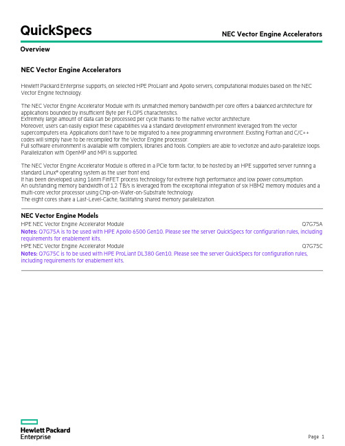
QuickSpecsNEC Vector Engine Accelerators OverviewNEC Vector Engine AcceleratorsHewlett Packard Enterprise supports, on selected HPE ProLiant and Apollo servers, computational modules based on the NEC Vector Engine technology.The NEC Vector Engine Accelerator Module with its unmatched memory bandwidth per core offers a balanced architecture for applications bounded by insufficient Byte per FLOPS characteristics.Extremely large amount of data can be processed per cycle thanks to the native vector architecture.Moreover, users can easily exploit these capabilities via a standard development environment leveraged from the vector supercomputers era. Applications don’t have to be migrated to a new programming environment. Existing Fortran and C/C++ codes will simply have to be recompiled for the Vector Engine processor.Full software environment is available with compilers, libraries and tools. Compilers are able to vectorize and auto-parallelize loops. Parallelization with OpenMP and MPI is supported.The NEC Vector Engine Accelerator Module is offered in a PCIe form factor, to be hosted by an HPE supported server running a standard Linux® operating system as the user front end.It has been developed using 16nm FinFET process technology for extreme high performance and low power consumption.An outstanding memory bandwidth of 1.2 TB/s is leveraged from the exceptional integration of six HBM2 memory modules and a multi-core vector processor using Chip-on-Wafer-on-Substrate technology.The eight cores share a Last-Level-Cache, facilitating shared memory parallelization.NEC Vector Engine ModelsHPE NEC Vector Engine Accelerator Module Q7G75A Notes: Q7G75A is to be used with HPE Apollo 6500 Gen10. Please see the server QuickSpecs for configuration rules, including requirements for enablement kits.HPE NEC Vector Engine Accelerator Module Q7G75C Notes: Q7G75C is to be used with HPE ProLiant DL380 Gen10. Please see the server QuickSpecs for configuration rules, including requirements for enablement kits.Description HPE NEC Vector Engine Accelerator ModuleHPE NEC VectorEngine Accelerator Module Q7G75A or Q7G75CImageHPE NEC Vector Engine Accelerator Module (VE) offers the best memory bandwidth per core to accelerate AI and HPC real applications. Its record Bytes per FL OPS ratio unleashes applications that are memory bandwidth bounded on current architectures. High sustained application performance of Vector Supercomputers is now available in this PCIe card form factor, at a fraction of the power consumption.Performance2.15 TFLOPS DP | 4.3 TFLOPS SP Memory Size48 GB HBM2 Stacked Memory Memory Bandwidth1.2 TB/s to HBM2 Stacked Memory Bytes/FLOPS0.56 Cores8 Vector Cores Each core with 3 FMA units, 1 Scalar unit, 64 registers of 16,384 bits (256 elements) - 128kB p. corePeer to Peer via PCIex16 PCIe Gen3 Power<300W CoolingPassive Cooling Form FactorDouble-width, Full Height, Full Length Supported Servers and Operating Systems Supported Servers Maximum number of VE cards per Server Server supported Operating Systems HPE ProLiant DL380 Gen10 Up to 3RHEL and CentOS 7.4, 7.5HPE Apollo 6500 Gen10 Up to 8RHEL and CentOS 7.4, 7.5 Software (orderseparately)NEC Fortran (2003, 2008), C (11), C++ (14) compilers. OpenMP 4.5. NEC MPI 3.1. BL AS, FFT, libc, Lapack, etc libraries. Stencil library. GNU profiler (gprof). GNU debugger (gdb) and Eclipse parallel tools platform (PTP). FtraceViewer, PROGINF tools. Notes:− HPE ProLiant DL380 Gen10 servers must be equipped with several options to receive the HPE NEC Vector Engine. Forexample, High Performance Heatsink Kit, High Performance Temperature Fan Kit, Graphics Cable Kit. Only a selection of HPE ProLiant DL380 Gen10 server models are supported with the HPE NEC Vector Engine Accelerator Module. Please see the HPE ProLiant DL380 Gen10 server QuickSpecs for configuration rules. − NEC Software Licenses are available from HPE on a per project basis.Performance of the Vector Engine 1.0 Type 10B-P•The Vector Engine 1.0 Type 10B-P PCIe module is built for HPC and AI.•8 vector cores.•16MB last-level-cache shared by all the cores at 3TB/s (400GB/s per core).•Each core has 64 registers of 16,384 bits (256 elements) for a total of 128kB per core.•Three Fused Multiply-Add (FMA), one Scalar and a few other functional units are available per core.• 2.15 TFLOPS of double-precision performance.• 4.30 TFLOPS of single-precision performance.•48GB HBM2 at 1.2 TB/s.•Power consumption: less than 300W.•x16 PCIe Gen 3.0 maximizes bandwidth between the HPE ProL iant server and the vector processors. The whole application being run on the Vector Engine, it is less subject to PCIe bottleneck than codes offloading functions to accelerators and transferring data constantly.•Vector processors can communicate directly when placed under the same root complex. Up to 8 VEs in an Apollo 6500 Gen10.Service and SupportService and SupportNotes:This option is covered under HPE Support Services / Service Contract applied to the HPE ProLiant Server. No separate HPE Support Services need to be purchased.Most HPE branded options sourced from HPE that are compatible with your product will be covered under your main product support at the same level of coverage, allowing you to upgrade freely. Please check HPE ProLiant Server documentation for more details on the services for this particular option.HPE Pointnext - Service and SupportGet the most from your HPE Products. Get the expertise you need at every step of your IT journey with HPE Pointnext Services. We help you lower your risks and overall costs using automation and methodologies that have been tested and refined by HPE experts through thousands of deployments globally. HPE Pointnext Advisory Services, focus on your business outcomes and goals, partnering with you to design your transformation and build a roadmap tuned to your unique challenges. Our Professional and Operational Services can be leveraged to speed up time-to-production, boost performance and accelerate your business. HPE Pointnext specializes in flawless and on-time implementation, on-budget execution, and creative configurations that get the most out of software and hardware alike.Consume IT on your termsHPE GreenLake brings the cloud experience directly to your apps and data wherever they are—the edge, colocations, or your data center. It delivers cloud services for on-premises IT infrastructure specifically tailored to your most demanding workloads. With a pay-per-use, scalable, point-and-click self-service experience that is managed for you, HPE GreenLake accelerates digital transformation in a distributed, edge-to-cloud world.•Get faster time to market•Save on TCO, align costs to business•Scale quickly, meet unpredictable demand•Simplify IT operations across your data centers and cloudsManaged services to run your IT operationsHPE GreenLake Management Services provides services that monitor, operate, and optimize your infrastructure and applications, delivered consistently and globally to give you unified control and let you focus on innovation. Recommended ServicesHPE Pointnext Tech Care.HPE Pointnext Tech Care is the new operational service experience for HPE products. Tech Care goes beyond traditional support by providing access to product specific experts, an AI driven digital experience, and general technical guidance to not only reduce risk but constantly search for ways to do things better. HPE Pointnext Tech Care has been reimagined from the ground up to support a customer-centric, AI driven, and digitally enabled customer experience to move your business forward. HPE Pointnext Tech Care is available in three response levels. Basic, which provides 9x5 business hour availability and a 2 hour response time. Essential which provides a 15 minute response time 24x7 for most enterprise level customers, and Critical which includes a 6 hour repair commitment where available and outage management response for severity 1 incidents.https:///services/techcareHPE Pointnext Complete CareHPE Pointnext Complete Care is a modular, edge-to-cloud IT environment service that provides a holistic approach to optimizing your entire IT environment and achieving agreed upon IT outcomes and business goals through a personalized and customer-centric experience. All delivered by an assigned team of HPE Pointnext Services experts. HPE Pointnext Complete Care provides: • A complete coverage approach -- edge to cloud•An assigned HPE team•Modular and fully personalized engagement•Enhanced Incident Management experience with priority access•Digitally enabled and AI driven customer experiencehttps:///services/completecareTechnical SpecificationsWarranty and Support ServicesWarranty and Support Services will extend to include HPE options configured with your server or storage device. The price of support service is not impacted by configuration details. HPE sourced options that are compatible with your product will be covered under your server support at the same level of coverage allowing you to upgrade freely. Installation for HPE options is available as needed. To keep support costs low for everyone, some high value options will require additional support. Additional support is only required on select high value workload accelerators, fibre channel switches, InfiniBand and UPS batteries over12KVA.See the specific high value options that require additional support hereProtect your business beyond warranty with HPE Support ServicesHPE Pointnext provides a comprehensive portfolio including Advisory and Transformational, Professional, and Operational Services to help accelerate your digital transformation. From the onset of your transformation journey, Advisory and Transformational Services focus on designing the transformation and creating a solution roadmap. Professional Services specializes in creative configurations with flawless and on-time implementation, and on-budget execution. Finally, operational services provides innovative new approaches like Flexible Capacity and Complete Care, to keep your business at peak performance. HPE is ready to bring together all the pieces of the puzzle for you, with an eye on the future, and make the complex simple.Parts and MaterialsHewlett Packard Enterprise will provide HPE-supported replacement parts and materials necessary to maintain the covered hardware product in operating condition, including parts and materials for available and recommended engineering improvements.Parts and components that have reached their maximum supported lifetime and/or the maximum usage limitations as set forth in the manufacturer's operating manual, product QuickSpecs, or the technical product data sheet will not be provided, repaired, or replaced as part of these services.The defective media retention service feature option applies only to Disk or eligible SSD/Flash Drives replaced by Hewlett Packard Enterprise due to malfunction.HPE Support CenterThe HPE Support Center is a personalized online support portal with access to information, tools and experts to support HPE business products. Submit support cases online, chat with HPE experts, access support resources or collaborate with peers. Learn more https:///hpesc/public/homeHPE's Support Center Mobile App* allows you to resolve issues yourself or quickly connect to an agent for live support. Now, you can get access to personalized IT support anywhere, anytime.HPE Insight Remote Support and HPE Support Center are available at no additional cost with a HPE warranty, HPE Support Service or HPE contractual support agreement.Notes:*HPE Support Center Mobile App is subject to local availability.For more informationVisit the Hewlett Packard Enterprise Service and Support website.Summary of ChangesDate Version History Action Description of Change15-Nov-2021 Version 3 Changed Service and Support section was updated.02-Dec-2019 Version 2 Changed Overview and Standard Features sections were updated.Q7G75C addition to be used with HPE ProLiant DL380 Gen10 02-Apr-2019 Version 1 New New QuickSpecsCopyrightMake the right purchase decision. Contact our presales specialists.ChatEmailCall© Copyright 2021 Hewlett Packard Enterprise Development LP. The information contained herein is subject to change without notice. The only warranties for Hewlett Packard Enterprise products and services are set forth in the express warranty statements accompanying such products and services. Nothing herein should be construed as constituting an additional warranty. Hewlett Packard Enterprise shall not be liable for technical or editorial errors or omissions contained herein.a00059759enw - 16363 - WorldWide - V3 - 15-November-2021Get updates。
light-based
Solving the subset-sum problem with alight-based deviceMihai Oltean,Oana MunteanDepartment of Computer Science,Faculty of Mathematics and Computer Science,Babe¸s-Bolyai University,Kog˘a lniceanu1,Cluj-Napoca,400084,Romania.moltean@cs.ubbcluj.rowww.cs.ubbcluj.ro/∼molteanAbstract.We propose a special computational device which uses lightrays for solving the subset-sum problem.The device has a graph-likerepresentation and the light is traversing it by following the routes givenby the connections between nodes.The nodes are connected by arcsin a special way which lets us to generate all possible subsets of thegiven set.To each arc we assign either a number from the given set ora predefined constant.When the light is passing through an arc it isdelayed by the amount of time indicated by the number placed in thatarc.At the destination node we will check if there is a ray whose totaldelay is equal to the target value of the subset sum problem(plus someconstants).1IntroductionUnconventional computing means computing by using new or unusual methods. Special properties of matter are usually exploited in an unconventional manner. Several unconventional techniques and approaches for attacking difficult prob-lems have been investigated so far:DNA computing[2],Quantum computing [28],Soap bubbles[1,6],Gear-based computers[29],Adiabatic algorithms[16] etc.Using light,instead of electric power,for performing computations is an exciting idea whose applications can be already seen on the market.This choice is motivated by the increasing number of real-world problems where the light-based devices could perform better than electric-based counterparts.Good examples in this direction can be found in thefield of Optical Character Recognition[31]. Another interesting example is the n-point discrete Fourier transform which can be performed in unit time by special light-based devices[13,24].In this paper we suggest a new way of performing computations by using some properties of light.The idea is used within a special device for solving the subset-sum problem.The problem asks tofind if there is a subset of given set A whose sum is B.2The device,which is very simple,has a graph-like structure.The nodes are connected by arcs in such way all possible subsets of A are generated.To each arc we assign either a number from the given set A,or a predefined constant. The length of an arc is directly proportional to the number assigned to it.Initially a light ray is sent to the start node.In each node the light is divided into2subrays.Each arc delays the ray by an amount of time equal to the number assigned to it.At the destination node we will check if there is a ray arriving in the destination node at the moment equal to the target value of B(plus some constants introduced by the system).The paper is organized as follows:Related work in thefield of optical com-puting is briefly overviewed in section2.The subset-sum problem is described in section3.The proposed device is presented in section4.The way in which the proposed device works is given in section4.4.A list of components required by the proposed device is given in plexity is computed in sec-tion6.Weaknesses of our device are discussed in section7.Section7.2gives a rough approximation for the size of the instances that can be solved by our device.Suggestions for improving the device are given in section7.5.Further work directions are suggested in section8.2Related workMost of the major computational devices today are using electric power in order to perform useful computations.Another idea is to use light instead of electrical power.It is hoped that optical computing could advance computer architecture and can improve the speed of data input and output by several orders of magnitude[9].Many theoretical and practical light-based devices have been proposed for dealing with various problems.Optical computation has some advantages,one of them being the fact that it can perform some operations faster than conventional devices.An example is the n-point discrete Fourier transform computation which can be performed,optically,in only unit time[13,24].Based on that,a solution to the subset sum problem can be obtained by discrete convolution.The idea is that the convolution of2functions is the same as the product of their frequencies representation[32].The quest for the light-based computers was started in1929by G.Tauschek who has obtained a patent on Optical Character Recognition(OCR)in Germany. Next step was made by Handel who obtained a patent on OCR.Those devices were mechanical and used templates for matching the characters.A photodetec-tor was placed so that when the template and the character to be recognized were lined up for an exact match,and a light was directed towards it,no light would reach the photodetector[31].Since then,thefield of OCR has grown steadily and recently has become an umbrella for multiple pattern recognition techniques(including Digital Character Recognition).An important practical step was made by Intel researchers who have devel-oped thefirst continuous wave all-silicon laser using a physical property called3 the Raman Effect[8,23,25,26].The device could lead to such practical appli-cations as optical amplifiers,lasers,wavelength converters,and new kinds of lossless optical devices.Another solution comes from Lenslet[17]which has created a very fast processor for vector-matrix multiplications(see Figure1(a)).This processor can perform up to8000Giga Multiple-Accumulate instructions per second.Lenslet technology has already been applied to data analysis using k−mean algorithm and video compression.A recent paper[27]introduces the idea of sorting by using some properties of light.The method called Rainbow Sort is based on the physical concepts of refraction and dispersion.It is inspired by the observation that light that traverses a prism is sorted by wavelength(see Figure1(b)).For implementing the Rainbow Sort one need to perform the following steps:–encode multiple wavelengths(representing the numbers to be sorted)into a light ray,–send the ray through a prism which will split the ray into n monochromatic rays that are sorted by wavelength,–read the output by using a special detector that receives the incoming rays.A stable version of the Rainbow Sort is proposed in[19].Naughton(et al.)proposed and investigated[20,30]a model called the con-tinuous space machine which operates in discrete time-steps over a number of two-dimensional complex-valued images of constant size and arbitrary spatial resolution.The(constant time)operations on images include Fourier transfor-mation,multiplication,addition,thresholding,copying and scaling.A system which solves the Hamiltonian path problem(HPP)[11]by using light and its properties has been proposed in[21,22].The device has the same structure as the graph where the solution is to be found.The light is delayed within nodes,whereas the delays introduced by arcs are constants.Because the problem asks that each node has to be visited exactly once,a special delaying system was designed.At the destination node we will search for a ray which has visited each node exactly once.This is very easy due to the special properties of the delaying system.3The subset-sum problemThe description of the subset-sum problem[7,11]is the following: Given a set of positive numbers A={a1,a2,...,a n}and another positive number B.Is there a subset of A whose sum equals B?We focus our attention on the YES/NO decision problem.We are not in-terested infinding the subset generating the solution.Actually we are interested tofind only if such subset does exist.The subset-sum problem arises in many real-word applications[12].4Fig.1.(a)A sketch of the Lenslet device used for performing vector-matrix multipli-cations.(b)Schematic view of the Rainbow Sort.5 The problem belongs to the class of NP-complete problems[11].No poly-nomial time algorithm is known for it.However,a pseudo-polynomial time al-gorithm does exist for this problem[11].The complexity of this algorithm is bounded by both n and B.The algorithm requires O(n∗B)storage space.4The proposed deviceThis section deeply describes the proposed system.Section4.1describes the properties of light which are useful for our device.Section4.2introduces the operations performed by the components of our device.Basic ideas behind our concept are given in section4.3.Some examples on how the system works are given in section4.4.4.1Useful properties of lightOur idea is based on two properties of light:–The speed of light has a limit.The value of the limit is not very important at this stage of explanation.The speed will become important when we will try to measure the moment when rays arrive at the destination node(see section7.1).What is important now is the fact that we can delay the ray by forcing it to pass through an opticalfiber cable of a certain length.–The ray can be easily divided into multiple rays of smaller intensity/power.Beam-splitters are used for this operation[3,9].4.2Operations performed within our deviceThe proposed device has a graph like structure.Generally speaking one operation is performed when a ray passes through a node and one operation is performed when a ray passes through an edge.–When passing through an arc the light ray is delayed by the amount of time assigned to that arc.–When the ray is passing through a node it is divided into a number of rays equal to the external degree of that node.Each obtained ray is directed toward one of the nodes connected to the current node.4.3The deviceThefirst idea for our device was that numbers from the given set A represent the delays induced to the signals(light)that passes through our device.For instance,if numbers a1,a3and a7generate the expected subset,then the total delay of the signal should be a1+a3+a7.If using light we can easily induce some delays by forcing the ray to pass through an optical cable of given length.This is why we have designed our device as a directed graph.Arcs,which are implemented by using optical cables,are labeled with numbers from the given6set A.Each number is assigned to exactly one arc and there are no two arcs having assigned the same number.There are n+1nodes connected by n arcs. At this moment of explanation we have a linear graph as the one shown in Figure 2.Fig.2.First version of our device.Each arc delays the ray by the amount of time written on it.Note that this device is not complete because it cannot generate all possible subsets of A.However,this is not enough because we also need a mechanism for skipping an arc.Only in this way we may generate all possible subsets of A.A possible way for achieving this is to add an extra arc(of length0)between any pair of consecutive nodes.Such device is depicted in Figure3.A light ray sent to start node will have the possibility to either traverse a given arc(from the upper part offigure)or to skip it(by traversing the arc of length0from the bottom offigure).Fig.3.Second version of our device.Each subset of A is generated,but this device cannot be implemented in practice because we cannot have cables of length0.In each node(but the last one)we place a beam-splitter which will split a ray into2subrays of smaller intensity.The device will generate all possible subsets of A.Each subset will delay one of the ray by an amount of time equal to the sum of the lengths of the arcs in that path.7 There is a problem here:even if theoretically we could have arcs of length 0,we cannot have cables of length0in practice.For avoiding this problem we have multiple solutions.Thefirst one was to use very short cables(let’s say of length )for arcs which are supposed to have length0.However,there is another problem here:we could obtain for instance the sum B written as B=a1+3∗ . Even if there is no subset of sum B,still there will be possible to have a signal at moment B due to the situation presented above.For avoiding this situation we have added a constant k to the length of each cable.The schematic view of this device is depicted in Figure4.Fig.4.A schematic representation of the device used for solving an instance with4 numbers.On each arc we have depicted its length.There are n cables of length k and n cables of length a i+k(1≤i≤n).This device does generate all possible subsets of A and it can be implemented in practiceWe can see that each path from Start to Destination contains exactly n time value k.Thus,at the destination we will not wait anymore at moment B. Instead we will wait for a solution at moment B+n∗k since all subsets will have the constant n∗k added.The device will generate all possible subsets of A.The good part is that we do not have to check all2n possible solutions.We will only have to check if there is a ray arriving at moment B+n∗k in the destination node.The signals generated by all other subsets are ignored and not recorded in any way.4.4How the system worksIn the graph depicted in Figure5the light will enter in Start node.It will be divided into2subrays of smaller intensity.These2rays will arrive into the second node at moments a1+k and k.Each of them will be divided into2subrays which will arrive in the3rd node at moments2∗k,a1+2∗k,a2+2∗k,a1+a2+2∗k. These rays will arrive at no more than4different moments.In the destination node we will have2n rays arriving at no more than2n different moments.The ray arriving at moment n∗k means the empty set.The ray arriving at moment a1+a2+...+a n+n∗k represents the full set.If there is a ray arriving at moment B+n∗k means that there is a subset of A of sum B.8Fig.5.The moments when different rays arrive in nodes.The moments are represented as sets because they might not be distinct9 If there are2rays arriving at the same moment in the Destination it simply means that there are multiple subsets which have the same sum.This is not a problem for us because we want to answer the YES/NO decision problem(see section3).We are not interested at this moment which is the subset generating the solution.Because we are working with continuous signal we cannot expect to have dis-crete output at the destination node.This means that rays arrival is notified by fluctuations in the intensity of the light.Thesefluctuations will be transformed, by a photodiode,influctuations of the electric power which will be easily read by an oscilloscope.5Physical implementationFor implementing the proposed device we need the following components:–a source of light(laser),–Several beam-splitters for dividing light rays into2subrays.A standard beam-splitter is designed using a half-silvered mirror(see Figure6),–A high speed photodiode for converting light rays into electrical power.The photodiode is placed in the destination node,–A tool for detectingfluctuations in the intensity of electric power generated by the photodiode(oscilloscope),–A set of opticalfiber cables having lengths equals to the numbers in the given set A(plus constant k)and another set of n cables havingfixed length k.These cables are used for connecting nodes.Fig.6.The way in which a ray can be split into2sub-rays by using a beam-splitter.106ComplexityThe time required to build the device has O(n∗B)complexity.We assume that all cables are shorter than B,otherwise they cannot participate to thefinal solution.Because the ray encoding the solution takes B+n∗k time to reach the destination node we may say that the complexity is O(B+n).The intensity of the signal decreases exponentially with the number of nodes. This is why the required power is proportional to2n.7Analysis of the proposed deviceThis section investigates some of the problems of the proposed device and some ways to deal with them.Section7.1computes the precision of solution represen-tation.The size of the instances that can be solved by our device having a limited length for cables is computed in section7.2.Section7.3shows how to handle the exponential decrease of power.Several problems that might be encountered dur-ing the physical implementation are discussed in section7.4.Section7.5shows how to improve the device by reducing the speed of light.7.1PrecisionA problem is that we cannot measure the moment B+n∗k exactly.We can do this measurement only with a given precision which depends on the tools involved in the experiments.Actually it will depend on the response time of the photodiode and the rise time of the oscilloscope.The rise-time of the best oscilloscope available on the market is in the range of picoseconds(10−12seconds).This means that if a signal arrives at the destination in the interval[B+n∗k−10−12,B+n∗k+10−12]we cannot be perfectly sure that we have a correct subset or another one which does not have the wanted property.This problem can be avoided if all cables are long enough.In what follows we will try to compute the length of the cables.We know that the speed of light is3·108m/s.Based on that we can easily compute the minimal cable length that should be traversed by the ray in order to be delayed with10−12seconds.This is obviously0.0003meters and it was obtained from equation:distance=speed∗timeThis value is the minimal delay that should be introduced by an arc.More than that,all lengths must be integer multiples of0.0003.We cannot allow to have cables whose lengths can be written as p∗0.0003+q,where p is an integer and q is a positive real number less than0.0003because by combining this kind of numbers we can have a signal in the above mentioned interval and that signal does not encode a subset whose sum is the expected one.11 Once we have the length for the minimal delay it is quite easy to compute the length of the other cables that are used in order to induce a certain delay. First of all we have to multiply/divide all given numbers with such factor that the less significant digit(greater than0)to be on thefirst position before the decimal place.For instance if we have the set A={0.001,4}we will multiply both numbers by1000.If we have the set A={100,2000}we have to divide both numbers by100.After this operation we will multiply the obtained numbers by 0.0003factor.This will ensure that if a signal will arrive in the interval[B+n∗k−10−12,B+ n∗k+10−12]we can be sure that it encodes the sum B+n∗k.7.2Problem sizeWe are also interested tofind the size of the instances that can be solved by our device.Regarding the cardinal of A we cannot make too many approximations because it actually depends on the available power and on the sensitivity of the measurement tools.However,having available a limited length(lets say3kilometers)for each cable,we can compute the maximal value for the numbers that can appear in A.We know that each number is less or equal to B.This is why we want to see how large B can be.Without reducing generality we may assume that all numbers are positive integers.We know that the shortest delay possible is0.0003meters(see section 7.1).Having a cable of3kilometers we may encode numbers less than107.Longer cables may also be available.Take for instance the optical cables linking the cities in a given country.We may easilyfind cables having300km. In this case we may work with numbers smaller than109.This is a little bit smaller than the largest integer value represented over32bits.7.3Power decreaseBeam splitters are used in our approach for dividing a ray in two subrays.Be-cause of that,the intensity of the signal is decreasing.In the worst case we have an exponential decrease of the intensity.For instance,in a graph with n nodes (destination node is not counted because there is no split there),each signal is divided(within each node)into2signals.Roughly speaking,the intensity of the signal will decrease2n times.This means that,at the destination node,we have to be able to detect very smallfluctuations in the intensity of the signal.For this purpose we can use a photomultiplier[10]which is an extremely sensitive detector of light in the ultraviolet,visible and near infrared range.This detector multiplies the signal produced by incident light by as much as108,from which even single photons can be detected.Also note that this difficulty is not specific to our system only.Other major unconventional computation paradigms,trying to solve NP-complete problems12share the same fate.For instance,a quantity of DNA equal to the mass of Earth is required to solve Hamiltonian Path Problem instances of200cities using DNA computers[14].7.4Technical difficultiesThere are many technical challenges that must be solved when implementing the proposed device.Some of them are:–Cutting the opticfibers to an exact length with high precision.Failing to accomplish this task can lead to errors in detecting if there was afluctuation in the intensity at moment B+n∗k,–Finding a high precision oscilloscope.This is an essential step for measuring the moment B+n∗k with high precision(see section7.1).7.5Improving the deviceThe speed of the light in opticfibers is an important parameter in our device. The problem is that the light is too fast for our measurement tools.We have either to increase the precision of our measurement tools or to decrease the speed of light.It is known that the speed of light traversing a cable is significantly smaller than the speed of light in the void mercially available cables have limit the speed of the ray wave up to60%from the original speed of light.This means that we can obtain the same delay by using a shorter cable.However,this method for reducing the speed of light is not enough for our purpose.The order of magnitude is still the same.This is why we have the search for other methods for reducing that speed.A very interesting solution was proposed in[15]which is able to reduce the speed of light by7orders of magnitude and even to stop it[4,18].In[4]they succeeded in completely halting light by directing it into a mass of hot rubidium gas,the atoms of which,behaved like tiny mirrors,due to an interference pattern in two control beams.This could help our mechanism significantly.However,how to use this idea for our device is still an open question because of the complex equipment involved in those experiments[15,18].By reducing the speed of light by7orders of magnitude we can reduce the size of the involved cables by a similar order(assuming that the precision of the measurement tools is still the same).This will help us to solve larger instances of the problem.8Conclusions and further workThe way in which light can be used for performing useful computations has been suggested in this paper.The techniques are based on the massive parallelism of the light ray.13 It has been shown the way in which a light-based device can be used for solving the subset-sum problem.Further work directions will be focused on:–implementing the proposed device,–cutting new cables each time when a new instance has to be solved is ex-tremely inefficient.This is whyfinding a simple way to reuse the previously utilized cables is a priority for our system,–automate the entire process,–Our device cannotfind the set of numbers representing the solution.It can only say if there is a subset or not.If there are multiple subsets we cannot distinguish them.However,the subset sum YES/NO decision problem is stilla NP-complete problem[11].We are currently investigating a way to storethe order of nodes so that we can easily reconstruct the path,–finding other non-trivial problems which can be solved by using the proposed device,–finding other ways to introduce delays in the system.The current solution requires cables that are too long and too expensive,–using other type of signals instead of light.Possible candidates are electric power and sound.References1.Aaronson S(2005),NP-complete problems and physical reality,ACM SIGACTNews Complexity Theory Column,March.ECCC TR05-026,quant-ph/0502072 2.Adleman L(1994)Molecular computation of solutions to combinatorial problems.Science266:1021-10243.Agrawal GP(2002)Fiber-optic communication systems.Wiley-Interscience;3rdedition4.Bajcsy M,Zibrov AS,Lukin MD(2003)Stationary pulses of light in an atomicmedium.Nature426:638-641.5.Bennett C,Bernstein E,Brassard G and Vazirani U(1997)Strengths and weak-nesses of quantum computing,SIAM put.,26(5):1510-15236.Bringsjord S,Taylor J(2004)P=NP,/04060567.Cormen TH,Leiserson CE,Rivest RR(1990)Introduction to algorithms.MITPress8.Faist J(2005)Optoelectronics:silicon shines on.Nature,433:691-6929.Feitelson DG(1988)Optical computing:A survey for computer scientists,MITPress10.Flyckt SO,Marmonier C(2002)Photomultiplier tubes:Principles and applications.Photonis,Brive,France11.Garey MR,Johnson DS(1979)Computers and intractability:A guide to NP-Completeness.Freeman&Co,San Francisco,CA12.Gilmore PC,Gomory RE(1965)Multistage Cutting Stock Problems of Two andMore Dimensions,Operations Research,Vol.13,No.1,pp.94-12013.Goodman JW(1982)Architectural development of optical data processing systems.Aust.J.Electr.Electron.Eng.2:139-1491414.Hartmanis J(1995)On the weight of computations.Bulletin of the EATCS55:136-13815.Hau LV,Harris SE,Dutton Z,Behroozi CH,(1999)Light speed reduction to17meters per second in an ultracold atomic gas.Nature397:594-59816.Kieu T.D(2003)Quantum algorithm for Hilbert’s tenth problem,Intl.Journal ofTheoretical Physics,42:1461-147817.Lenslet website(2005),18.Liu C,Dutton Z,Behroozi CH,Hau LV(2001)Observation of coherent opticalinformation storage in an atomic medium using halted light pulses.Nature409:490-49319.Murphy N,Naughton TJ,Woods D,Henley B,McDermott K,Duffy E,van derBurgt PJM,Woods N(2006)Implementations of a model of physical sorting.From Utopian to Genuine Unconventional Computers workshop,Adamatzky A,Teuscher C,(editors),Luniver Press79-10020.Naughton TJ(2000)A model of computation for Fourier optical processors.InLessard RA,Galstian T(editors),Optics in Computing,Proc.SPIE4089:24-34 21.Oltean M(2006)A light-based device for solving the Hamiltonian path problem.Unconventional Computing,Calude C.(et al.)(Eds),LNCS4135,Springer-Verlag, 217-22722.Oltean M(2007)Solving the Hamiltonian path problem with a light-based com-puter,Natural Computing,Springer-Verlag,(accepted)23.Paniccia M,Koehl S(2005)The silicon solution.IEEE Spectrum,IEEE Press,October24.Reif JH,Tyagi A(1997)Efficient parallel algorithms for optical computing withthe discrete Fourier transform primitive.Applied optics36(29):7327-734025.Rong H,Jones R,Liu A,Cohen O,Hak D,Fang A,Paniccia M(2005)A continuous-wave Raman silicon laser.Nature433:725-72826.Rong H,Liu A,Jones R,Cohen O,Hak D,Nicolaescu R,Fang A,Paniccia M(2005)An all-silicon Raman laser.Nature433:292-29427.Schultes D(2005)Rainbow Sort:Sorting at the speed of light.Natural Computing.Springer-Verlag,5(1):67-8228.Shor P(1997)Polynomial-time algorithms for prime factorization and discretelogarithms on a quantum computer.SIAM put.,26(5):1484-1509,1997 29.Vergis A.,Steiglitz K.,and Dickinson B(1986)The complexity of analog compu-tation.,Mathematics and Computers in Simulation,28:91-11330.Woods D,Naughton TJ(2005)An optical model of computation.Theoretical Com-puter Science,334(1-3):227-25831.Optical Character Recognition@Wikipedia(2006),/wiki/Optical character recognition32.Thoughts on the Subset Sum Problem(P vs.NP)(2006)/2006/06/11/thoughts-on-the-subset-sum-problem-p-vs-np/。
计算机组织与结构 Computer Organization and ArchitecturePPT精品文档25页

The control unit is that part of the processor that activates the various components of the processor. This part looks at the functioning of the control unit and its implementation using microprogramming.
docin/sundae_meng
Architecture & Organization 2
All Intel x86 family share the same basic architecture The IBM System/370 family share the same basic architecture This gives code compatibility
Organization attributes: those hardware details transparent to the programmer ( control signals, interfaces, memory technology). e.g. Is there a hardware multiply unit or is it done by repeated addition?
docin/sundae_meng
Computer organization is how featuቤተ መጻሕፍቲ ባይዱes are implemented, in other words, computer organization refers to the operational units and their interconnections that realize the architectural specifications.
Computer architecture
Computer architecture
Usually, in a computer system, low-level machine attribute to the top conceptual structure and functional properties of traditional machine
seen that there is an architecture at all levels of the hierarchy. The architecture proposed by Amdahl refers to the traditional machinelevel architecture, that is, the attributes of the traditional machine level that are seen by machine-language programmers.
一旦设计了指令集和微架构,就必须开发出实用的机器。这个设计过程称为实现。 实现通常不被认为是体系结构设计,而是硬件设计工程。实现可以进一步分解为 几个步骤: 1、逻辑实现 2、巡回的执行 3、物理实现 4、设计验证
课程名称英文翻译
课程名称英文翻译自然辩证法natural dialectics英语english language数理统计numeral statistic/numerical statistic人工智能及其体系结构artificial intelligence & its architecture高级数理逻辑advanced numerical logic高级程序设计语言的设计与实现advanced programming language s de sign & implementation软件工程基础foundation of software engineering专业英语specialized english计算机网络computer network高级计算机体系结构advanced computer architectureibm汇编及高级语言的接口ibm assembly & its interfaces with advanc ed programming languages分布式计算机系统distributed computer system / distributed system计算机网络实验computer network experiment高等代数elementary algebra数学分析mathematical analysis中共党史history of the chinese communist party算法语言algorithmic language体育physical education英语english language力学实验mechanics-practical德育moral educationpascal语言pascal language政治经济学political economics电学实验electrical experiment数字逻辑mathematical logic普通物理general physics计算方法computing method离散数学discrete mathematics汇编原理principles of assembly概率与统计probability & statistics数据结构data structure哲学philosophy微机原理principles of microcomputer编译方法compilation method系统结构system structure操作系统原理principles of operating system 文献检索documentation retrieval数据库概论introduction to database网络原理principles of network人工智能artificial intelligence算法分析algorithm analysis毕业论文graduation thesisadvanced computational fluid dynamics 高等计算流体力学advanced mathematics 高等数学advanced numerical analysis 高等数值分析algorithmic language 算法语言analogical electronics 模拟电子电路artificial intelligence programming 人工智能程序设计audit 审计学automatic control system 自动控制系统automatic control theory 自动控制理论auto-measurement technique 自动检测技术basis of software technique 软件技术基础calculus 微积分catalysis principles 催化原理chemical engineering document retrieval 化工文献检索circuitry 电子线路college english 大学英语college english test (band 4) cet-4college english test (band 6) cet-6college physics 大学物理communication fundamentals 通信原理comparative economics 比较经济学complex analysis 复变函数论computational method 计算方法computer graphics 图形学原理computer organization 计算机组成原理computer architecture 计算机系统结构computer interface technology 计算机接口技术contract law 合同法cost accounting 成本会计circuit measurement technology 电路测试技术database principles 数据库原理design & analysis system 系统分析与设计developmental economics 发展经济学discrete mathematics 离散数学digital electronics 数字电子电路digital image processing 数字图像处理digital signal processing 数字信号处理econometrics 经济计量学economical efficiency analysis for chemical technology 化工技术经济分析economy of capitalism 资本主义经济electromagnetic fields & magnetic waves 电磁场与电磁波electrical engineering practice 电工实习enterprise accounting 企业会计学equations of mathematical physics 数理方程experiment of college physics 物理实验experiment of microcomputer 微机实验experiment in electronic circuitry 电子线路实验fiber optical communication system 光纤通讯系统finance 财政学financial accounting 财务会计fine arts 美术functions of a complex variable 单复变函数functions of complex variables 复变函数functions of complex variables & integral transformations 复变函数与积分变换fundamentals of law 法律基础fuzzy mathematics 模糊数学general physics 普通物理graduation project(thesis) 毕业设计(论文)graph theory 图论heat transfer theory 传热学history of chinese revolution 中国革命史industrial economics 工业经济学information searches 情报检索integral transformation 积分变换intelligent robot(s); intelligence robot 智能机器人international business administration 国际企业管理international clearance 国际结算international finance 国际金融international relation 国际关系international trade 国际贸易introduction to chinese tradition 中国传统文化introduction to modern science & technology 当代科技概论introduction to reliability technology 可靠性技术导论java language programming java 程序设计lab of general physics 普通物理实验linear algebra 线性代数management accounting 管理会计学management information system 管理信息系统mechanic design 机械设计mechanical graphing 机械制图merchandise advertisement 商品广告学metalworking practice 金工实习microcomputer control technology 微机控制技术microeconomics & macroeconomics 西方经济学microwave technique 微波技术military theory 军事理论modern communication system 现代通信系统modern enterprise system 现代企业制度monetary banking 货币银行学motor elements and power supply 电机电器与供电moving communication 移动通讯music 音乐network technology 网络技术numeric calculation 数值计算oil application and addition agent 油品应用及添加剂operation & control of national economy 国民经济运行与调控operational research 运筹学optimum control 最优控制petroleum chemistry 石油化学petroleum engineering technique 石油化工工艺学philosophy 哲学physical education 体育political economics 政治经济学principle of compiling 编译原理primary circuit (反应堆)一回路principle of communication 通讯原理principle of marxism 马克思主义原理principle of mechanics 机械原理principle of microcomputer 微机原理principle of sensing device 传感器原理principle of single chip computer 单片机原理principles of management 管理学原理probability theory & stochastic process 概率论与随机过程procedure control 过程控制programming with pascal language pascal语言编程programming with c language c语言编程property evaluation 工业资产评估public relation 公共关系学pulse & numerical circuitry 脉冲与数字电路refinery heat transfer equipment 炼厂传热设备satellite communications 卫星通信semiconductor converting technology 半导体变流技术set theory 集合论signal & linear system 信号与线性系统social research 社会调查software engineering 软件工程spc exchange fundamentals 程控交换原理specialty english 专业英语statistics 统计学stock investment 证券投资学strategic management for industrial enterprises 工业企业战略管理technological economics 技术经济学television operation 电视原理theory of circuitry 电路理论turbulent flow simulation and application 湍流模拟及其应用visual c++ programming visual c++程序设计windows nt operating system principles windows nt操作系统原理word processing 数据处理上文已完。
计算机专业英语名词翻译
第一章(计算机系统概论)digital computer 数字计算机decimal digits 十进制数字binary 二进制bit 位ASCII 美国国家信息交换标准代码computer system 计算机系统hardware system 硬件系统software system 软件系统I/O devices 输入输出设备central processing unit(CPU) 中央处理器memory 存储器application software 应用软件video game 计算机游戏system software 系统软件register 寄存器floating point data浮点数据Boolean布尔值character data字符数据EBCDIC扩充的二十一进制交换代码punched cards穿孔卡片magnetic tape磁带main memory主存vacuum tubes电子管magnetic drum磁鼓transistors晶体管solid-state devices固体器件magnetic cores磁芯integrated circuit(IC)集成电路silicon chip硅芯片multiprogramming多道程序设计timessharing分时分时技术minicomputers小型计算机mainframe大型计算机large-scaleintegrated(LSI)大规模集成very-large-scale integrated(VLSI)超大规模集成word processing文字处理eletronic spreedsheets电子表格database management programs数据库管理程序desktop publishing桌面印刷personalcomputer(PC)个人计算机microcomputer微型计算机storage capacities存储容量stand-alone computer独立计算机local area network(LAN)局域网peripheral devices外部设备assembly line流水线supercomputer巨型计算机第二章(计算机系统结构)memmory subsystem存储子系统I/O subsystem输入输出子系统bus总线system bus系统总线chip 芯片address bus地址总线instructions指令memory location存储单元data bus数据总线control bus控制总线local bus 局部总线microprocessor微处理器register set寄存器组arithmetic logic unit(ALU)运算器clock cycle时钟周期control unit控制器computer architecture计算机体系结构introduction format指令格式addressing modes寻址方式introduction set指令集internal memory内存main memory主存Random Access Memory(RAM)随机存取存储器Read Only Memory (ROM)只读存储器secondary storage副主存储器vitual memory虚拟存储器Dynamic RAM(DRAM)动态存储器refresh circuitry刷新电路Static RAM(SRAM)静态RAMcache memory高速缓冲存储器masked ROM掩膜ROMPROM可编程RAMEPROM可擦写PROMultraviolet light紫外线EEPROM or EEPROM电擦写PROMbasic input/output system(BIOS)基本输入输出系统flash EEPROM 快闪存储器memory hierarchy 存储器体系结构auxiliary memory 辅助存储器storage memory 存储容量keyboard 键盘alphanumeric key字母数字键function key 功能键cursor key 光标键numeric keypad 数字键mouse 鼠标touch screen触屏infrared ray红外线monitor 监视器display screen显示屏laser printer激光打印机ink-jet printer喷墨打印机dot-matrix printer点针式打印机modem调制解调器input-output interface(I/O interface)输入输出接口peripheral外部设备,外设interrupt中断program counter程序计数器vectored interrupt向量中断nonvectored interrupt非向量中断interrupt vector中断向量Direct Memory Acess(DMA)直接存储器存取timeout超时第三单元(计算机体系结构)parallel processing 并行操作serial operations 串行操作instructions stream 指令流data dream 数据流SISD 单指令单数据流SIMD 单指令多数据流MISD 多指令单数据流MIMD 多指令多数据流pipeline processing 流水线处理combinational circuit 组合电路multiplier 乘法器adder 加法器clock pulse 时钟脉冲vector processing 向量处理one-dimensional array 一维数组scalar processer 标量处理器vector instructions 向量指令CISC 复杂指令集计算机decoder 译码器RISC 精简指令集计算机backward compatibility 向下兼容第四单元(算法与数据结构)algorithm 算法parallel algotithm 并行算法primitive 原语syntax 语法semantics 语义pseudocode 伪码exhaustive search 穷举搜索divide-and-conquer algorithm 分治算法dynamic programming 动态规划bottom-up 自上而下top-down 自下而上array 数组one-dimensional array 一维数组pointer 指针program counter 程序计数器instruction pointer 指令指针list 列表linked list 链表singly-linked list 单向链表double-linked list 双向链表circularly-linked list 循环链表FIFO 先进先出LIFO 后进先出stack 栈push 压栈pop 出栈stack pointer 栈指针queue 队列tree 树root 根level 层次degree of a node 结点的度depth of a tree树的深度binary tree 二叉树traversal 遍历M-way search tree M向搜索树第五章(编程语言)Program 程序Program language 程序设计语言Software engineering 软件工程Pseudocode 伪码Flowchart 流程图Coding 编码Program testing 程序测试Desk-checking 手工检查Documentation 文档User documentation 用户文档Operator documentation 操作员文档Programmer documentation 程序员文档Machine language 机器语言Assembly languages 汇编语言High-level languages 高级语言RAD(rapid application development) 快速应用开发Natural language 自然语言Artificial intelligence(AI) 人工智能Compile 编译Assemble 汇编Source code 源代码Object code 目标代码Linker 连接器Executable file 可执行文件Object-oriented programming 面向对象的程序设计Object 对象Class 类ADT(abstract data type)抽象数据类型Member variable 成员变量Class variable 类变量Member function 成员函数Inheritance 继承Derived class 派生类Overload 超载Message 消息Static binding 静态绑定Dynamic binding 动态绑定Polymorphism 多态性Visual programming 可视化编程Markup language 标记语言HTML(hyper text markup language)超文本标记语言Hyperlink 超链接XML(extensible markup language) 可扩展标记语言Java virtual machine java虚拟机第六章(操作系统)Application software 应用软件System software 系统软件Utility software 实用软件Operating system(OS)操作系统Shell 操作系统的外壳程序Graphical user interface(GUI)图形用户界面Kernel 内核Serial processing 串行处理Job 作业Batch processing 批处理Simple batch systems 简单批处理系统Multiprogrammed batch systems 多道程序批处理系统Monitor 监控程序Scheduler 调度程序Multiprogramming 多道程序Multitasking 多任务Time-sharing systems 分时系统Uniprogramming 单道进程Process 进程Process management 进程管理Process control block 进程控制块Mutual exclusion 互斥Multiprocessing 多处理,多进程Distributed processing 分布式管理Concurrent processes 并发处理Deadlock 死锁Synchronize process同步处理Semaphore 信号量Reusable resource 可复用性资源I/O buffers 输入/输出缓冲区I/O channel 输入/输出通道Deadlock prevention 死锁预防Deadlock detection 死锁检测Deadlock avoidance 死锁避免Virtual memory 虚拟内存Logical reference 逻辑引用Real addresse 实地址Paging 分页Segmentation 分段Virtual address 虚拟地址Physical addresses 物理地址Real-time process 实时处理File management 文件管理Plug and play(PnP) 即插即用第七单元(应用软件)application software 应用软件word processing 字处理软件spreadsheet 电子表格personal finance 个人理财presentation graphic 演示图形database manager 数据库管理软件groupware 群件desktop accessory 桌面辅助工具browsers 浏览区desktop publishing 桌面印刷project management 项目管理CAD 计算机辅助设计CAM 计算机辅助制造multimedia authoring 多媒体发布animation 动画MIDI 乐器数字化接口speech synthesis 语音合成insertion point 插入点scroll bar 滚动条window 窗口menu bar 菜单栏pull-down menu 下拉式菜单Button 按钮toolbar 工具条dialog box 对话框default value 缺省值(默认值)macro 宏OLE 对象链接和嵌入clipboard 剪切板column 列row 行cell 单元格cell address 单元格地址cell pointer 单元格指针formula 公式function 函数bar chart 柱形图line chart 线图pie chart 圆饼图workflow software 工作流软件PIM 个人信息管理软件Web browser 浏览器World Wide Web 万维网home page 主页第八单元(数据库)DBMS 数据库管理系统instance 实例schema 模式physical schema 物理模式存储模式内模式logical schema 逻辑模式概念模式模式subschema 子模式外模式data independence 数据独立性physical data independence 物理数据独立性logical data independence 逻辑数据独立性data model 数据模型entity-relationship model 实体联系模型object-oriented model 面向对象模型semantic data model 语义数据类型functional data model 功能数据模型entity 实体entity set 实体集mapping cardinality 映射基数abstract data type 抽象数据类型attribute 属性relation 关系tuple 元组primary key 主键super key 超健candidate key 候选键foreign key 外键DDL 数据定义语言data dictionary 数据字典DML 数据操纵语言procedure DML 过程化DML nonprocedure DML 非过程化DMLSQL 结构化查询语言view 视图the relational algebra 关系代数the tuple relational calculus 元组关系演算atomicity 原子性consistency 一致性duration 持久性transaction 事物DBA 数据库管理员。
MCIMX535DVV1C;中文规格书,Datasheet资料
Freescale SemiconductorData Sheet: Advance InformationDocument Number: IMX53CECRev. 4.1, 2/2012MCIMX53xDOrdering Information See Table 1 on page3This document contains information on a new product. Specifications and information herein are subject to change without notice.1IntroductionThe i.MX53xD multimedia application processor is Freescale Semiconductor’s latest addition to a growing family of multimedia-focused products offering high performance processing optimized for lowest power consumption.The i.MX53xD processor features Freescale’s advanced implementation of the ARM™ core, which operates at clock speeds as high as 1.2GHz and interfaces with DDR2/LVDDR2-800, LPDDR2-800, or DDR3-800 DRAM memories. This device is suitable for applications such as the following:•Tablets•Smart devices•Netbooks (web tablets)•Nettops (Internet desktop devices)•Thin clients •Media phones •Internet monitors•High-end mobile Internet devices (MID)i.MX53xD Applications Processors for Consumer Products1.Introduction . . . . . . . . . . . . . . . . . . . . . . . . . . . . . . . . . . . 11.1.Ordering Information . . . . . . . . . . . . . . . . . . . . . . . 31.2.Features . . . . . . . . . . . . . . . . . . . . . . . . . . . . . . . . . 32.Architectural Overview . . . . . . . . . . . . . . . . . . . . . . . . . . . 72.1.Block Diagram . . . . . . . . . . . . . . . . . . . . . . . . . . . . 73.Modules List . . . . . . . . . . . . . . . . . . . . . . . . . . . . . . . . . . . 83.1.Special Signal Considerations . . . . . . . . . . . . . . . 174.Electrical Characteristics . . . . . . . . . . . . . . . . . . . . . . . . 174.1.Chip-Level Conditions . . . . . . . . . . . . . . . . . . . . . 174.2.Power Supply Requirements and Restrictions . . . 254.3.I/O DC Parameters . . . . . . . . . . . . . . . . . . . . . . . . 284.4.Output Buffer Impedance Characteristics . . . . . . 344.5.I/O AC Parameters . . . . . . . . . . . . . . . . . . . . . . . . 384.6.System Modules Timing . . . . . . . . . . . . . . . . . . . . 454.7.External Peripheral Interfaces Parameters . . . . . . 674.8.XT AL Electrical Specifications . . . . . . . . . . . . . . 1435.Boot Mode Configuration . . . . . . . . . . . . . . . . . . . . . . . 1445.1.Boot Mode Configuration Pins . . . . . . . . . . . . . . 1445.2.Boot Devices Interfaces Allocation . . . . . . . . . . . 1455.3.Power Setup During Boot . . . . . . . . . . . . . . . . . . 1466.Package Information and Contact Assignments . . . . . 1476.1.19x19mm Package Information . . . . . . . . . . . . . 1476.2.19 x 19mm, 0.8 Pitch Ball Map . . . . . . . . . . . . . 1666.3.12 x 12 mm Package on Package (PoP) Information1707.Revision History . . . . . . . . . . . . . . . . . . . . . . . . . . . . . . 198Introduction•High-end portable media players (PMP) with HD video capability•Portable navigation devices (PND)The flexibility of the i.MX53xD architecture allows for its use in a wide variety of applications. As the heart of the application chipset, the i.MX53xD processor provides all the interfaces for connecting peripherals, such as WLAN, Bluetooth™, GPS, hard drive, camera sensors, and dual displays. Features of the i.MX53xD processor include the following:•Applications processor—The i.MX53xD processors boost the capabilities of high-tier portable applications by satisfying the ever increasing MIPS needs of operating systems and games.Freescale’s Dynamic V oltage and Frequency Scaling (DVFS) provides significant power reduction, allowing the device to run at lower voltage and frequency with sufficient MIPS for tasks such as audio decode.•Multilevel memory system—The multilevel memory system of the i.MX53xD is based on the L1 instruction and data caches, L2 cache, internal and external memory. The i.MX53xD supportsmany types of external memory devices, including DDR2, low voltage DDR2, LPDDR2, DDR3, NOR Flash, PSRAM, cellular RAM, NAND Flash (MLC and SLC), OneNAND™, and managed NAND including eMMC up to rev 4.4.•Smart speed technology—The i.MX53xD device has power management throughout the IC that enables the rich suite of multimedia features and peripherals to consume minimum power in both active and various low power modes. Smart speed technology enables the designer to deliver a feature-rich product requiring levels of power far lower than industry expectations.•Multimedia powerhouse—The multimedia performance of the i.MX53xD processor ARM core is boosted by a multilevel cache system, Neon (including advanced SIMD, 32-bit single-precision floating point support) and vector floating point coprocessors. The system is further enhanced bya multi-standard hardware video codec, autonomous image processing unit (IPU), SD and HD720ptriple video (TV) encoder with triple video DAC, and a programmable smart DMA (SDMA)controller.•Powerful graphics acceleration—Graphics is the key to mobile game, navigation, web browsing, and other applications. The i.MX53xD processors provide two independent, integrated graphics processing units: an OpenGL® ES 2.0 3D graphics accelerator (33Mtri/s, 200Mpix/s, and800Mpix/s z-plane performance) and an OpenVG™1.1 2D graphics accelerator (200Mpix/s).•Interface flexibility—The i.MX53xD processor supports connection to a variety of interfaces, including LCD controller for two displays and CMOS sensor interface, high-speed USB on-the-go with PHY, plus three high-speed USB hosts, multiple expansion card ports (high-speedMMC/SDIO host and others), 10/100 Ethernet controller, and a variety of other popular interfaces (PATA, UART, I2C, and I2S serial audio, among others).•Advanced security—The i.MX53xD processors deliver hardware-enabled security features that enable secure e-commerce, digital rights management (DRM), information encryption, secureboot, and secure software downloads. For detailed information about the i.MX53xD securityfeatures contact a Freescale representative.The i.MX53xD application processor is a follow-on to the i.MX51, with improved performance, power efficiency, and multimedia capabilities.Introduction1.1Ordering InformationTable 1 provides ordering information.1.2FeaturesThe i.MX53xD multimedia applications processor (AP) is based on the ARM Platform, which has the following features:•MMU, L1 instruction and L1 data cache •Unified L2 cache•Maximum frequency of the core (including Neon, VFPv3 and L1 cache): 1–1.2GHz•Neon coprocessor (SIMD media processing architecture) and vector floating point (VFP-Lite) coprocessor supporting VFPv3•TrustZone The memory system consists of the following components:•Level 1 cache:—Instruction (32Kbyte)—Data (32Kbyte)•Level 2 cache:—Unified instruction and data (256Kbyte)•Level 2 (internal) memory:—Boot ROM, including HAB (64Kbyte)—Internal multimedia/shared, fast access RAM (128Kbyte) —Secure/non-secure RAM (16Kbyte)•External memory interfaces:—16/32-bit DDR2-800, LV-DDR2-800 or DDR3-800 up to 2Gbyte —32-bit LPDDR2—8/16-bit NAND SLC/MLC Flash, up to 66MHz, 4/8/14/16-bit ECC —8/16-bit NOR Flash, PSRAM, and cellular RAM.Table 1. Ordering InformationPart NumberMask Set FeaturesCase Temperature Range (°C)Package 11Case TEPBGA-2 and FC-PBGA are RoHS compliant, lead-free MSL (moisture sensitivity level) 3.MCIMX535DVV1C N78C 1GHz, full feature set -20 to +8519 x 19 mm, 0.8 mm pitch BGACase TEPBGA-2MCIMX535DVV2C N78C 1.2GHz, full feature set -20 to +8519 x 19 mm, 0.8 mm pitch BGACase TEPBGA-2SCIMX538DZK1CN78C1GHz, full feature set-20 to +8512 x 12 mm PoP , 0.4 mm pitch BGACase FC-PBGAIntroduction—32-bit multiplexed mode NOR Flash, PSRAM & cellular RAM.—8-bit Asynchronous (DTACK mode) EIM interface.—All EIM pins are muxed on other interfaces (data with NFC pins). I/O muxing logic selects EIM port, as primary muxing at system boot.—Samsung OneNAND™ and managed NAND including eMMC up to rev 4.4 (in muxed I/O mode)The i.MX53xD system is built around the following system on chip interfaces:•64-bit AMBA AXI v1.0 bus—used by ARM platform, multimedia accelerators (such as VPU, IPU, GPU3D, GPU2D) and the external memory controller (EXTMC) operating at 200MHz.•32-bit AMBA AHB 2.0 bus—used by the rest of the bus master peripherals operating at 133MHz.•32-bit IP bus—peripheral bus used for control (and slow data traffic) of the most system peripheral devices operating at 66MHz.The i.MX53xD makes use of dedicated hardware accelerators to achieve state-of-the-art multimedia performance. The use of hardware accelerators provides both high performance and low power consumption while freeing up the CPU core for other tasks.The i.MX53xD incorporates the following hardware accelerators:•VPU, version 3—video processing unit•GPU3D—3D graphics processing unit, OpenGL ES2.0, version3, 33Mtri/s, 200Mpix/s, and 800Mpix/s z-plane performance, 256Kbyte RAM memory•GPU2D—2D graphics accelerator, OpenVG1.1, version1, 200Mpix/s performance,•IPU, version 3M—image processing unit•ASRC—asynchronous sample rate converterThe i.MX53xD includes the following interfaces to external devices:NOTENot all interfaces are available simultaneously, depending on I/Omultiplexer configuration.•Hard disk drives:—PATA, up to U-DMA mode 5, 100MByte/s—SATA I, 1.5Gbps•Displays:—Five interfaces available. Total rate of all interfaces is up to 180Mpixels/s, 24bpp. Up to two interfaces may be active at once.—Two parallel 24-bit display ports. The primary port is up to 165Mpix/s (for example, UXGA at60Hz).—LVDS serial ports: one dual channel port up to 165Mpix/s or two independent single channel ports up to 85MP/s (for example, WXGA at60Hz) each.—TV-out/VGA port up to 150Mpix/s (for example, 1080p60).•Camera sensors:Introduction —Two parallel 20-bit camera ports. Primary up to 180-MHz peak clock frequency, secondary up to 120-MHz peak clock frequency.•Expansion cards:—Four SD/MMC card ports: three supporting 416Mbps (8-bit i/f) and one enhanced port supporting 832Mbps (8-bit, eMMC4.4).•USB—High-speed (HS) USB2.0OTG (up to 480Mbps), with integrated HS USB PHY—Three USB2.0 (480Mbps) hosts:–High-speed host with integrated on-chip high-speed PHY–Two high-speed hosts for external HS/FS transceivers through ULPI/serial, support IC-USB • Miscellaneous interfaces:—One-wire (OWIRE) port—Three I2S/SSI/AC97 ports, supporting up to 1.4Mbps, each connected to audio multiplexer (AUDMUX) providing four external ports.—Five UART RS232 ports, up to 4.0Mbps each. One supports 8-wire, the other four support 4-wire.—Two high speed enhanced CSPI (ECSPI) ports plus one CSPI port—Three I2C ports, supporting 400kbps—Fast Ethernet controller, IEEE1588 V1 compliant, 10/100Mbps—Two controller area network (FlexCAN) interfaces, 1Mbps each—Sony Phillips Digital Interface (SPDIF), Rx and Tx—Enhanced serial audio interface (ESAI), up to 1.4Mbps each channel—Key pad port (KPP)—Two pulse-width modulators (PWM)—GPIO with interrupt capabilitiesThe system supports efficient and smart power control and clocking:•Supporting DVFS (dynamic voltage and frequency scaling) technique for low power modes •Power gating SRPG (State Retention Power Gating) for ARM core and Neon•Support for various levels of system power modes•Flexible clock gating control scheme•On-chip temperature monitor•On-chip oscillator amplifier supporting 32.768kHz external crystal•On-chip LDO voltage regulators for PLLsSecurity functions are enabled and accelerated by the following hardware:•ARM TrustZone including the TZ architecture (separation of interrupts, memory mapping, and so on)•Secure JTAG controller (SJC)—Protecting JTAG from debug port attacks by regulating or blocking the access to the system debug featuresIntroduction•Secure real-time clock (SRTC)—Tamper resistant RTC with dedicated power domain and mechanism to detect voltage and clock glitches•Real-time integrity checker, version 3 (RTICv3)—RTIC type1, enhanced with SHA-256 engine •SAHARAv4 Lite—Cryptographic accelerator that includes true random number generator (TRNG)•Security controller, version 2 (SCCv2)—Improved SCC with AES engine, secure/non-secure RAM and support for multiple keys as well as TZ/non-TZ separation•Central security unit (CSU)—Enhancement for the IIM (IC Identification Module). CSU is configured during boot by e-fuses, and determines the security level operation mode as well as the TrustZone (TZ) policy•Advanced High Assurance Boot (A-HAB)—HAB with the following embedded enhancements: SHA-256, 2048-bit RSA key, version control mechanism, warm boot, CSU, and TZ initializationNOTEThe actual feature set depends on the part number as described in Table1.Functions such as video hardware acceleration with 2D and 3D hardwaregraphics acceleration may not be enabled for specific part numbers.Architectural Overview2Architectural OverviewThe following subsections provide an architectural overview of the i.MX53xD processor system.2.1Block DiagramFigure 1 shows the functional modules in the i.MX53xD processor system.Figure 1. i.MX53xD System Block DiagramNOTEThe numbers in brackets indicate number of module instances. For example, PWM (2) indicates two separate PWM peripherals.Application Processor Smart DMA (SDMA)Shared PeripheralsAP PeripheralsARM Cortex A8ARM Cortex A8Platform Timers CSPI UART (4)GPT PWM (2)EPIT (2)GPIOx32 (7)WDOG (2)OWIRE I 2C (3)IOMUXC IIM AUDMUX KPP Boot ROM SSI (2)RTICv3SCCv2SRTC CSU Fuse BoxDebug DAP TPIUFIRI SAHARAv4Lite Security TZICImage ProcessingUSB OTG + 3 HS PortsCTI (2)ECSPIInternal USB PHY2USB PHY1External Memory I/F RAM 144KB Subsystem (IPU)TV-EncoderLDB LCD Display-1,2Domain (AP)Composite CVBS/ S-Video Component RGB, YCC (HD TV-Out / VGA)SJCNeon, VFPv3L2 cache 256KB ETM, CTI0,1L1 I/D cache IrDA XVRWLANUSB OTG(dev/host)JTAG(IEEE1149.1)Bluetooth Keypad Access.Conn.MMC/SD eMMC/eSDGPSRF/IFRF / IF IC’sAudio, Power Mngmnt.SPBAFlexCAN (2)DigitalAudioCAN i/feSDHCv2 (3)UART SPDIF Rx/Tx ASRCVideo Proc. Unit (VPU)3D Graphics Proc. Unit (GPU3D)G-Memory 256KB2D Graphics Proc. Unit (GPU2D )A X I a n d A H B S w i t c h F a b r i cLVDS(WSXGA+)Battery CtrlDeviceNOR/NAND Flash Ethernet 10/100MbpsFEC (IEEE1588)Camera (2)64KB Clock and ResetPLL (4)CCM GPC SRC XTALOSC(2)CAMP (2)Temperature SensoreSDHCv3Camera(2)(EXTMC)LCD Display (2)SSI ECSPI ESAI P-ATA SATA + Temp MonSATA /P-ATA HDDDDR2/DDR3/LPDDR2Modules List3Modules ListThe i.MX53xD processor contains a variety of digital and analog modules. Table2 describes these modules in alphabetical order.Table2. i.MX53xD Digital and Analog BlocksBlockMnemonicBlock Name Subsystem Brief DescriptionARM ARM Platform ARM The ARM Cortex TM A8 platform consists of the ARM processor version r2p5(with T rustZone) and its essential sub-blocks. It contains the 32Kbyte L1instruction cache, 32Kbyte L1 data cache, Level 2 cache controller and a256Kbyte L2 cache. The platform also contains an event monitor anddebug modules. It also has a NEON coprocessor with SIMD mediaprocessing architecture, a register file with 32/64-bit general-purposeregisters, an integer execute pipeline (ALU, Shift, MAC), dualsingle-precision floating point execute pipelines (FADD, FMUL), aload/store and permute pipeline and a non-pipelined vector floating point(VFP Lite) coprocessor supporting VFPv3.ASRC AsynchronousSample RateConverter MultimediaPeripheralsThe asynchronous sample rate converter (ASRC) converts the samplingrate of a signal associated to an input clock into a signal associated to adifferent output clock. The ASRC supports concurrent sample rateconversion of up to 10 channels of about -120dB THD+N. The sample rateconversion of each channel is associated to a pair of incoming and outgoingsampling rates.The ASRC supports up to three sampling rate pairs.AUDMUX Digital AudioMultiplexer MultimediaPeripheralsThe AUDMUX is a programmable interconnect for voice, audio, andsynchronous data routing between host serial interfaces (for example,SSI1, SSI2, and SSI3) and peripheral serial interfaces (audio and voicecodecs). The AUDMUX has seven ports (three internal and four external)with identical functionality and programming models. A desired connectivityis achieved by configuring two or more AUDMUX ports.CAMP-1 CAMP-2Clock Amplifier Clocks,Resets, andPower ControlClock amplifierCCM GPC SRC Clock ControlModuleGlobal PowerControllerSystem ResetControllerClocks,Resets, andPower ControlThese modules are responsible for clock and reset distribution in thesystem, as well as for system power management.The system includes four PLLs.CSPI ECSPI-1 ECSPI-2ConfigurableSPI, EnhancedCSPIConnectivityPeripheralsFull-duplex enhanced synchronous serial interface, with data rates16-60Mbit/s. It is configurable to support master/slave modes. In Mastermode it supports four slave selects for multiple peripherals.CSU Central SecurityUnit Security The central security unit (CSU) is responsible for setting comprehensive security policy within the i.MX53xD platform, and for sharing securityinformation between the various security modules. The security controlregisters (SCR) of the CSU are set during boot time by the high assuranceboot (HAB) code and are locked to prevent further writing.Modules ListDEBUG Debug System SystemControl The debug system provides real-time trace debug capability of both instructions and data. It supports a trace protocol that is an integral part of the ARM Real Time Debug solution (RealView).Real-time tracing is controlled by specifying a set of triggering and filtering resources, which include address and data comparators, threecross-system triggers (CTI), counters, and sequencers.debug access port (DAP)— The DAP provides real-time access for the debugger without halting the core to system memory, peripheral register, debug configuration registers and JTAG scan chains.EXTMC External MemoryController ConnectivityPeripheralsThe EXTMC is an external and internal memory interface. It performsarbitration between multi-AXI masters to multi-memory controllers, dividedinto four major channels, fast memories (DDR2/DDR3/LPDDR2) channel,slow memories (NOR-FLASH / PSRAM / NAND-FLASH etc.) channel,internal memory (RAM, ROM) channel and graphical memory (GMEM)channel.In order to increase the bandwidth performance, the EXTMC separates thebuffering and the arbitration between different channels so parallelaccesses can occur. By separating the channels, slow accesses do notinterfere with fast accesses.EXTMC Features:•64-bit and 32-bit AXI ports•Enhanced arbitration scheme for fast channel, including dynamic master priority, and taking into account which pages are open or closed andwhat type (read or write) was the last access•Flexible bank interleaving•Support 16/32-bit DDR2-800 or DDR3-800 or LPDDR2.•Support up to 2GByte DDR memories.•Support NFC, EIM signal muxing scheme.•Support 8/16/32-bit Nor-Flash/PSRAM memories (sync and asyncoperating modes), at slow frequency. (8-bit is not supported onD[23]-D[16]).•Support 4/8/14/16-bit ECC, page sizes of 512-B, 2-KB and 4-KBNand-Flash (including MLC)•Multiple chip selects (up to 4).•Enhanced DDR memory controller, supporting access latency hiding•Support watermark for security (internal and external memories)EPIT-1 EPIT-2EnhancedPeriodic InterruptTimerTimerPeripheralsEach EPIT is a 32-bit “set and forget” timer that starts counting after theEPIT is enabled by software. It is capable of providing precise interrupts atregular intervals with minimal processor intervention. It has a 12-bitprescaler for division of input clock frequency to get the required timesetting for the interrupts to occur, and counter values can be programmedon the fly.ESAI Enhanced SerialAudio Interface ConnectivityPeripheralsThe enhanced serial audio interface (ESAI) provides a full-duplex serial portfor serial communication with a variety of serial devices, includingindustry-standard codecs, SPDIF transceivers, and other processors.The ESAI consists of independent transmitter and receiver sections, eachsection with its own clock generator.The ESAI has 12 pins for data and clocking connection to external devices.Table2. i.MX53xD Digital and Analog Blocks (continued) BlockMnemonicBlock Name Subsystem Brief DescriptionModules ListESDHCV3-3Ultra-High-Speed eMMC /SD HostController ConnectivityPeripheralsUltra high-speed eMMC / SD host controller, enhanced to support eMMC4.4 standard specification, for 832MBps.•Port 3 is specifically enhanced to support eMMC 4.4 specification, for double data rate (832Mbps, 8-bit port).ESDHCV3 is backward compatible to ESDHCV2 and supports all thefeatures of ESDHCV2 as described below.ESDHCV2-1 ESDHCV2-2 ESDHCv2-4EnhancedMulti-Media Card/Secure DigitalHost ControllerEnhanced multimedia card / secure digital host controller•Ports 1, 2, and 4 are compatible with the “MMC System Specification”version4.3, full support and supporting 1, 4 or 8-bit data.The generic features of the eSDHCv2 module, when serving as SD / MMChost, include the following:•Can be configured either as SD / MMC controller•Supports eSD and eMMC standard, for SD/MMC embedded type cards•Conforms to SD Host Controller Standard Specification, version2.0, fullsupport.•Compatible with the SD Memory Card Specification, version1.1•Compatible with the SDIO Card Specification, version1.2•Designed to work with SD memory, miniSD memory, SDIO, miniSDIO,SD Combo, MMC and MMC RS cards•Configurable to work in one of the following modes:—SD/SDIO 1-bit, 4-bit—MMC 1-bit, 4-bit, 8-bit•Full/high speed mode.•Host clock frequency variable between 32kHz to 52MHz•Up to 200Mbps data transfer for SD/SDIO cards using 4 parallel datalines•Up to 416Mbps data transfer for MMC cards using 8 parallel data linesFEC Fast EthernetController ConnectivityPeripheralsThe Ethernet media access controller (MAC) is designed to support both10Mbps and 100Mbps Ethernet/IEEE Std 802.3™ networks. An externaltransceiver interface and transceiver function are required to complete theinterface to the media.The i.MX53xD also consists of HW assist for IEEE1588™ standard. See,TSU and CE_RTC (IEEE1588) section for more details.FIRI Fast InfraredInterface ConnectivityPeripheralsFast infrared interfaceFLEXCAN-1 FLEXCAN-2FlexibleController AreaNetworkConnectivityPeripheralsThe controller area network (CAN) protocol was primarily, but notexclusively, designed to be used as a vehicle serial data bus. Meets thefollowing specific requirements of this application: real-time processing,reliable operation in the EXTMC environment of a vehicle,cost-effectiveness and required bandwidth. The FLEXCAN is a fullimplementation of the CAN protocol specification, Version2.0B (ISO11898), which supports both standard and extended message frames at1Mbps.Table2. i.MX53xD Digital and Analog Blocks (continued)BlockMnemonicBlock Name Subsystem Brief Description分销商库存信息: FREESCALE MCIMX535DVV1C。
- 1、下载文档前请自行甄别文档内容的完整性,平台不提供额外的编辑、内容补充、找答案等附加服务。
- 2、"仅部分预览"的文档,不可在线预览部分如存在完整性等问题,可反馈申请退款(可完整预览的文档不适用该条件!)。
- 3、如文档侵犯您的权益,请联系客服反馈,我们会尽快为您处理(人工客服工作时间:9:00-18:30)。
!
For the DAXPY loop, a we can generate a C code as below.
low=1; /*Assume start element at 1*/ vL = n % mvL; /*find the odd – size piece */ for(j=0; j<=n/mvL; j++){ /*Outer Loop*/ for(i=low; i<=low+vL-1;i++){ /*Inner loop-runs for length vL*/ y[i] = a*x[i] + y[i]; /*Start of next vector*/ } low = low + vL; /*Find start of next vector*/ vL = mvL; /* reset length to max */ }
COMP4211- Advanced Computer Architecture Yian Sun 16
27/04/2004
15
27/04/2004
ï Using Convoys, results in
ห้องสมุดไป่ตู้
!
Greatly reduced instruction bandwidth " Six instructions instead of 600.
COMP4211- Advanced Computer Architecture Yian Sun 9 27/04/2004 COMP4211- Advanced Computer Architecture Yian Sun 10
27/04/2004 COMP4211- Advanced Computer Architecture Yian Sun 7 27/04/2004
BVA ñ the components cont.
! !
!
Vector load-store unit " Loads and stores vector to and from memory. Special-purpose registers " Vector length " Vector mask registers Set of Scalar registers " Provide data as input to the vector functional units. " Compute addresses to pass to the Load-Store unit. " In VMIPS # 32 general purpose and 32 floating-point registers.
COMP4211- Advanced Computer Architecture Yian Sun
!
Problem " Position in memory of adjacent elements in may not be sequential. Set up time could be enormous. " E.g. Matrix Multiplication. Solution " Distance seperating elements is called the Stride. " Store the stride in a register, so only a single load or store is required.
! !
!
!
Hardware need only check for data hazards between two instructions, once per operand. " More instructions per data check. Memory access for entire vector, not a single word. " Reduced Latency Multiple vector instructions in progress. " Further parallelism
!
Ordinary scalar pipeline unit + Vector unit. Two Types – " Vector-register -> all operations except load and store based on registers. " Memory-memory -> all operations are memory to memory. Concentrate on Vector-register, particularly VMIPS architecture.
27/04/2004
COMP4211- Advanced Computer Architecture Yian Sun
11
27/04/2004
COMP4211- Advanced Computer Architecture Yian Sun
12
Real World Issues (1)
Vector – Length Control ! Problem " How do we support operations where the length is unknown or not the vector length? ! Solution " Provide a vector-length register, solves problem only if real length is less than Maximum Vector Length. " Use Technique Called strip mining.
27/04/2004
COMP4211- Advanced Computer Architecture Yian Sun
5
27/04/2004
COMP4211- Advanced Computer Architecture Yian Sun
6
BVA ñ the components
Vector register " Fixed length, holds a single vector " In VMIPS # 2 read and 1 write port. # 8 vector registers, 64 elements each Vector functional units " Fully pipelined, start new operations every cycle. " Might contain scalar function unit. Control unit " Detect structural and data hazards.
27/04/2004
COMP4211- Advanced Computer Architecture Yian Sun
13
27/04/2004
COMP4211- Advanced Computer Architecture Yian Sun
14
Example: Strip Mining
!
Real World Issues (2)
Strip mining
! !
! !
Generating code where vector operations are done for a size no greater than MVL. Create 2 loops " One that handles any number of iterations multiple of MVL. " Another that handles the remaining iterations. Code becomes vectorizable. Careful handling of VLR needed.
Introduction cont.
Why Vector Processors? ! It is equivalent to executing an entire loop " Reducing instruction fetch and decode bandwidth. ! Each instruction guarantees each result is independent on other results in same vector " No data hazard check needed in an instruction. " Executed using array of paralleled functional units, or deep pipeline.
COMP4211- Advanced Computer Architecture Yian Sun 8
Example: MIPS Vs VMIPS
Parallelism using convoys
Convoys " A set of instructions that could begin execution together. " Consider this sequence of code.
27/04/2004
COMP4211- Advanced Computer Architecture Yian Sun
3
27/04/2004
COMP4211- Advanced Computer Architecture Yian Sun
4