袖珍IMPULSE XP使用说明(1)
IMPULSE手提激光测距仪的结构和操作简要
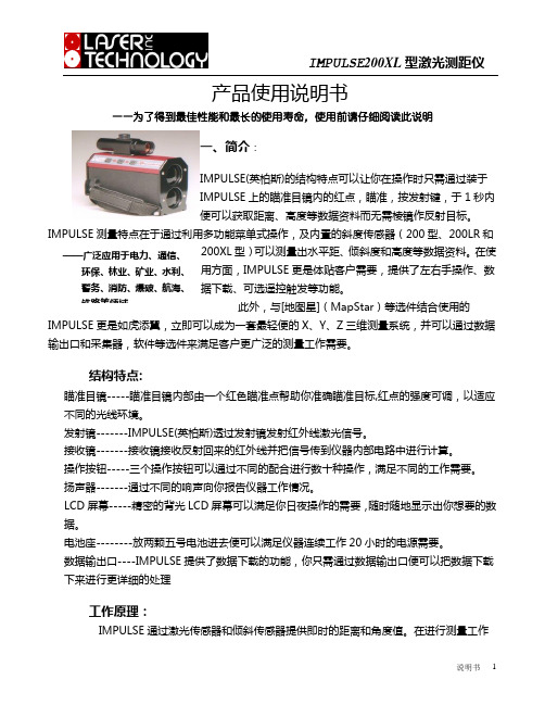
产品使用说明书——为了得到最佳性能和最长的使用寿命,使用前请仔细阅读此说明一、简介:IMPULSE(英柏斯)的结构特点可以让你在操作时只需通过装于IMPULSE 上的瞄准目镜内的红点,瞄准,按发射键,于1秒内便可以获取距离、高度等数据资料而无需棱镜作反射目标。
IMPULSE 测量特点在于通过利用多功能菜单式操作,及内置的斜度传感器(200型、200LR 和200XL 型)可以测量出水平距、倾斜度和高度等数据资料。
在使用方面,IMPULSE 更是体贴客户需要,提供了左右手操作、数据下载、可选遥控触发等功能。
此外,与[地图星](MapStar )等选件结合使用的IMPULSE 更是如虎添翼,立即可以成为一套最轻便的X 、Y 、Z 三维测量系统,并可以通过数据输出口和采集器,软件等选件来满足客户更广泛的测量工作需要。
结构特点:瞄准目镜-----瞄准目镜内部由一个红色瞄准点帮助你准确瞄准目标,红点的强度可调,以适应不同的光线环境。
发射镜-------IMPULSE(英柏斯)透过发射镜发射红外线激光信号。
接收镜-------接收镜接收反射回来的红外线并把信号传到仪器内部电路中进行计算。
操作按钮-----三个操作按钮可以通过不同的配合进行数十种操作,满足不同的工作需要。
扬声器-------通过不同的响声向你报告仪器工作情况。
LCD 屏幕-----精密的背光LCD 屏幕可以满足你日夜操作的需要,随时随地显示出你想要的数据。
电池座--------放两颗五号电池进去便可以满足仪器连续工作20小时的电源需要。
数据输出口----IMPULSE 提供了数据下载的功能,你只需通过数据输出口便可以把数据下载下来进行更详细的处理工作原理:IMPULSE通过激光传感器和倾斜传感器提供即时的距离和角度值。
在进行测量工作时。
IMPULSE 由发射镜射出一束红外线,红外线碰到目标物反射回接收镜,而IMPULSE 的激光传感器则以计算红外线短脉冲飞逝的时间计算确定距离值,倾斜传感器则负责测量垂角、计算确定高度、仰角、斜度、水平距离等数据资料。
霍尼韦尔进口impulsexp单一检测仪
霍尼韦尔进口impulsexp单一检测仪霍尼韦尔单一气体检测仪,霍尼韦尔XP单一检测仪,霍尼韦尔impulsexp单一气体检测仪在各个方面而言都是您的首选。
XP是全部关于优选项的。
霍尼韦尔单一气体检测仪的操作:a:开机或需要时,显示屏、电池、传感器、声光震动报警设备进行自检。
b:通过使用带有TempraSUREZtm热冲击修正和Reflex/tm传感器保护的SureCe/tm传感器,XP能确保在不利操作条件中提高准确度和可靠性。
AB:相对而言,维护并不是那么容易。
内置元件衰变补偿将校准时间间隔延长到了12个月。
由于具有典型的传感器寿命(至少两年)和三年的电池寿命*,操作成本降到了最低。
用户可以轻易地替换电池和传感器。
霍尼韦尔进口XP单一气体检测仪的产品特性:1、坚固耐用的外壳体积小、重量轻坚固,防冲击,可应对各种天气状况配备鳄鱼夹一防止意外丢失2、操作可靠开机或褥要时,显示屏、电池、传感器、声光振动报警设备进行自检使用已获专利的SureCeIITM和ReflexTM传感器技术TempraSURETM温度补偿和冲击防护周期性频闪和声音提示,提高可靠性。
卓越的EMC/RFI性能靠近无线电话或手机不会误报警RFI抗忧性能超过最严格的工业标准3、使用便捷开机即用单键操作适合各种语言的直观图标用户可通过菜单进行设置提供软件模拟使用指导标配有振动报警4、成本效益佳传感器哀减补偿技术使得标定间隔达12个月(仅H2S/C0) 可替换的传感器与电池传感器寿命至少2年电池寿命通常为3年*(低电池电量警告)尺寸:93mm (H) *50MM(W)*27MM(D) 初始及运行成本低5、高清晰背光显示屏持续显示气体浓度TWA/STEL和两级瞬时报警并带峰值保持显示电池寿命、标定及自检状态6、有效的气体报警指示报警和背光相互结合,加强提示独特的95分贝双音频报警霍尼韦尔进口impulsexp单一检测仪公司相关产品:霍尼韦尔进口XP单一气体检测仪、霍尼韦尔四合一气体检测仪、加拿大BW气体检测仪、加拿大BW多功能气体检测仪、正压式空气呼吸器、送风式空气呼吸器、自吸式10米长管空气呼吸器、固定式气体泄漏报警器、家用天然气泄漏报警器、救援三脚架、消防救援三脚架、井口爬梯、防坠器、有限空间作业设备等。
minipal仪器使用指南

原子吸收分光光度计AA-6300
等离子发射光谱仪ICPE-9000
Cr6+的选择性定量分析-Uvmini-1240
RoHS检测程序
电子电器类样品的机械拆分流程
使用EDXRF-Epsilon 5进行定量分析
• 检验机构 (ITS)
• 需求:
– 检验能力 – 样品的多变性 (基体、形状…) – 低耗/高速 (与 ICP法相比)
0-200
Ba Cu
0-600.7 0-21.1
Ni
0-10.6
S:670 S :78
Cl:810 Cl:21.7
Ti
0-112
Zn
0-198
Zn
0-5.1
测量条件
Application Plastic
Element & analyzed line CrKα、CdKα、 Hg Lα、 PbLβ1、BrKα
标准样品的浓度范围(ppm)
Br Cd Cr Hg
TOXEL 0-163.3 0-28.4 0-24.8 0-5.3
JSAC(5 )
EC680 808 EC681 98
VDA (4)
ABS (13)
PVC (13)
32-960 28-970
Mg
0-43.4
140.8 21.7 40.9407 23-980
按鍵中, 鎘含量 >300 ppm
品质案例-2
2002年9月西班牙环保部门检查发现中国 出口到该国的玩具 “悠悠球” 铅含量超标, 于是 西班牙禁止进口生产的“悠悠球”
EU环保法规对中国企业的影响
• 根据中国电器工业协会统计,我国机电产品出口 在我国出口中所占比重达55%。而欧盟已经成为 中国机电产品出口的主要市场。由于中国厂商环 保理念和工艺水平的落后,RoHS指令使得将近 270亿美元的中国机电产品面临欧盟的环保壁垒。
霍尼韦尔单一气体检测仪impulse xp中文使用操作说明

霍尼韦尔单一气体检测仪 impulse XP 中文操作详解
霍尼韦尔单一气体检测仪impulse xp分类:氧气检测仪、一氧化 碳检测仪、硫化氢检测仪、氢气检测仪、氯气检测仪、二氧化硫 检测仪、氰化氢检测仪、氨气检测仪、二氧化氮检测仪(具体参 数见下表)
2012.07.09
产品描述
开关机
• 开机:按下前面板右侧的“开/关”键约1秒 钟,Impulse XP 将会进入开机预热自检状 态,具体表现为报警灯和蜂鸣器闪烁、鸣 叫5次后进入30秒钟的预热倒计时。如果仪 器正常,显示窗出现符号提示,如果有故 障则出现符号提示,表示自检失败 • 关机:按下“开/关”键并保持5秒(显示窗 口出现5秒倒 机键两次
倒计时20秒完 毕显示
可检测气体及报警参数
不同气体检测仪价格不同,具体详询:0531-89702982,15154174034霍尼韦尔一级代理
报警描述
• • • •
如需了解更多详情或采购仪器请致电: 霍尼韦尔(中国)安全防护设备有限公司 渠道部 我们的服务热线:0531-89702982 负责人:15154174034朱萍 (工作时间:周一至周六 8:00-17:30)
Sarix IMP 系列室外迷你球机使用手册说明书

C3956M-CN (10/13)Sarix ®IMP 系列 室外迷你球机 使用手册2目录重要声明 (5)使用须知 (5)广播和电视信号的干扰 (5)法律提示 (5)视频质量警告 (5)选择帧率注意事项 (5)开放源代码软件 (6)关于CCC 电源线的声明 (6)KCC 认证 (6)Korean Class A EMC (6)Korean Class B EMC (6)ESD 警告 (6)网络拓扑结构声明 (6)法律提示(关于音频使用) (6)前言 (7)1.产品概述 (8)1.1 尺寸大小 (8)1.2 外形特征 (9)2.安装和连接摄像机 (10)2.1 标准配备 (10)2.2 可选附件 (10)2.3 安装 (10)2.3.1 检查外观 (10)2.3.2 拆卸摄像机 (11)2.3.3 连接配线 (11)2.3.4 安装摄像机 (11)32.3.5 调整摄像机拍摄位置 (16)2.3.6 调整焦距 (16)2.3.7 网络布局 (17)2.3.8 系统需求 (17)2.4 连接摄像机 (18)2.4.1 默认IP地址 (19)2.4.2 连接电脑&图像查看准备 (19)3. 管理和配置摄像机 (20)3.1 实时显示 (20)3.2 设置 (22)3.2.1 系统 (22)3.2.2 网络 (25)3.2.3 图像 (33)3.2.4 A/V 数据流 (39)3.2.5 用户 (44)3.2.6 事件 (47)技术参数 (57)Pelco故障诊断联系信息 (60)关于产品尺寸图的说明 (60)重要声明使用须知该设备遵照FCC章程第15项条款制造。
操作本设备必须遵循以下两个条件:(1)不对周围环境产生有害干扰。
(2)该设备须接受任何收到的外部干扰,包括可能影响该设备正常工作的干扰。
广播和电视信号的干扰根据FCC章程第15项,本设备经过测试,符合数码设备A级标准。
这些标准为在居民区安装提供了有效的保护,该设备会产生、使用、和发射电磁波,如不按照说明书安装使用,可能会对无线电通信造成干扰。
Impulse(霍尼韦尔) X4 系列使用说明书
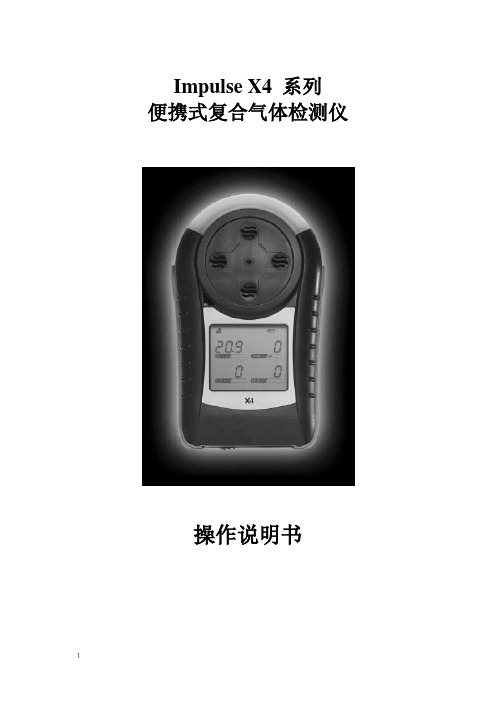
Impulse X4 系列便携式复合气体检测仪操作说明书!重要提示:!在首次使用仪器以前请认真阅读本手册,您将会掌握仪器正确的使用方法和了解仪器的功能,包括操作,维护,功能设置等内容。
!为了使操作者更安全,请按照手册中的要求,定期对仪器进行标定。
!如果在使用过程中,遇到的故障或问题在本手册中没有提到,请直接联系制造商Zellweger Analytics,或联系当地的代理商/服务商。
!警告和注意:·更换任何元器件都有可能损坏仪器的本质安全结构。
·如果需要使用存储卡,请选用Zellweger Analytics 提供的存储卡(订货号2566-0435),使用其它的存储卡有可能损坏仪器的本质安全结构。
·在允许的储存期之后激活检测器,有可能影响仪器的使用性能和保质期。
·应使用许可的5号干电池,如劲量电池,不要使用质量低下的干电池,以免影响仪器的本质安全性能。
·在更换电池时,应同时更换2节型号相同的新电池。
·在电池欠压提示后,应尽快更换新电池,以免旧电池漏液损坏仪器。
·在低温环境下,电池的寿命会缩短。
·更换电池时,应该在安全环境下进行。
·当更换任何一个传感器的情况下,都需要对仪器进行标定。
·在每天使用以前,应完成仪器的自检过程。
·定期的对仪器用标气进行测试,检查声、光、振动报警是否正常。
·标定时应选用厂家或国家认证合格企业提供的标准气体。
·标定时应在良好通风的环境下进行,以避免污染。
·不要在仪器电量不足的情况下标定。
·不要在富氧的环境下使用本仪器。
·可燃气体传感器的灵敏度会受到高浓度硫化物,卤素化合物,含硅化合物,以及含铅气体或蒸汽的影响,也叫“中毒”,应避免在以上的环境中使用仪器,如果必须使用,则使用完后应对仪器进行检测和标定,以免影响以后的使用。
霍尼韦尔impulsexp使用说明
impulse XP使用简介1 面板说明:报警灯显示屏腰带夹气体种类上键蜂鸣器下键开/关键传感器2 开/关机:按下前面板右侧的“开/关”键约1秒钟,Impulse XP 将会进入开机预热自检状态,具体表现为报警灯和蜂鸣器闪烁、鸣叫5次后进入30秒钟的预热倒计时。
如果仪器正常,显示窗出现符号提示,如果有故障则出现符号提示,表示自检失败,请参见后附详细说明。
关机时,按下“开/关”键并保持5秒(显示窗口出现5秒倒计时)仪器关机。
3 显示符号:A:电池电量B:故障指示C:正常工作提示D:氧气和毒气一级报警符号毒气二级报警符号E:氧气二级报警符号F:毒气的TWA 和STEL符号G:标定符号H:峰值符号I:浓度值和单位J:报警指示符Impulse XP的液晶显示窗具有背景灯光显示功能,在任何报警条件和按下任意键后都会激发背景灯光显示。
4 气体报警点设置:Impulse XP具有两级浓度报警点设置,对于毒气还具有8小时暴露平均浓度极限TWA和15分钟最大暴露平均浓度极限STEL报警设置。
用户可根据当地的国家法律和地方法规的要求对Impulse XP 的报警点进行设置。
出厂设置如下:(英国标准)气体类型量程一级报警点二级报警点TWA报警点STEL报警点氧气0-30%vol %vol %vol ------- ------一氧化碳0-1000ppm 35ppm 100ppm 35ppm 400ppm硫化氢0-250ppm 10ppm 15ppm 10ppm 15ppm氢气0-1000ppm 100ppm 500ppm ------- ------二氧化氮0-150ppm 3ppm 5ppm 3ppm 5ppm氯气0-50ppm 1ppm 1ppm二氧化硫0-150ppm 2ppm 5ppm 2ppm 5ppm氢氰酸0-100ppm 5ppm 10ppm 5ppm 10ppm氨气0-100ppm 25ppm 50ppm 25ppm 35ppm报警描述:报警类型显示声音报警灯光报警振动报警一级报警每秒3声每秒闪烁3次每秒两次二级报警每秒5声每秒闪烁5次每秒两次STEL报警每秒5声每秒闪烁5次每秒两次TWA报警每秒5声每秒闪烁5次每秒两次5 峰值,TWA和STEL显示模式:a. 正常显示b. TWA/STEL显示模式c. 峰值显示STEL模式TWA 模式如果想清除峰值,则在屏幕显示峰值时,按下“开/关”键一次,清除当前峰值并返回到正常的检测状态。
密理博便携式多参数中文操作手册
Spectroquant ®Move100手持式多参数比色计操作手册目录1 准备工作. . . . . . . . . . . . . . . . . . . . . . . . . . . . . . . . . . . . . . . . . . . . . . . . . .31.1 包装内容. . . . . . . . . . . . . . . . . . . . . . . . . . . . . . . . . .. . . . . .. . . . . . . . . . . . . . 31.2 装入可充电电池. . . . . . . . . . . . . . . . . . . . . . . . . . . . . . . . . . . . . . . . . . . . . . .31.2.1 更换电池组. . . . . . . . . . . . . . . . . . . . . . . . . . . . . . . . . . . . . . . . . . . .41.2.2 储存数据-重要信息. . . . . . . . . . . . . . . . . . . . . . . . . . . . . . . . . . . . 41.3 键盘说明. . . . . . . . . . . . . . . . . . . . . . . . . . . . . . . . . . . . . . . . . . . . . . . . . . . . .41.4 首次启动MOVE100 多参数比色计. . . . . . . . . . . . . . . . . . . . . . . . . . . . . . . .51.5 模式Mode 菜单一览. . . . . . . . . . . . . . . . . . . . . . . . . . .. . . . . . . . . . . . . . . . .121.6 设置语言. . . . . . . . . . . . . . . . . . . . . . . . . . . . . . . . . . . . . . . . . . . . . . . . . . . . .131.7 删除数据. . . . . . . . . . . . . . . . . . . . . . . . . . . . . . . . . . . . . . . . . . . . . . . . . . . . .141.8 设置时间日期. . . . . . . . . . . . . . . . . . . . . . . . . . . . . . .. . . . . . . . . .. . . . . . . . . 141.9 显示日期时间. . . . . . . . . . . . . . . . . . . . . . . . . . . . . . .. . . . . . . . . . . . . . . . . . .151.10 自动关机功能. . . . . . . . . . . . . . . . . . . . . . . . . . . . . . . . .. . . . . . . . . . . . . . . .151.11 屏幕背景光. . . . . . . . . . . . . . . . . . . . . . . . . . . . . . . . .. . . . . . . . . . . . . . . . . .152 工作状态. . . . . . . . . . . . . . . . . . . . . . . . . . . . . . . . . . . . . . . . . . . . . . . . . . .162.1 选择测试方法. . . . . . . . . . . . . . . . . . . . . . . . . . . . . . . . . . . . . . . . . . . . . . . . . 162.2 使用测试试剂进行测试. . . . . . . . . . . . . . . . .. . . . . . . . . . . . . . . . . . . . . . . . . .182.3 多层次测试. . . . . . . . . . . . . . . . . . . . . . . . . . . . . . . . . . . . . . . . . . . . . . . . . . . 222.4 更改测试结果参考当量. . . . . . . . . . . . . . . . . . . . . .. . . . . . . . . . . . . . . . . . . . .232.5 测试吸光度. . . . . . . . . . . . . . . . . . . . . . . . . . . . .. . . . . . . . . . . . . . . . . . . . . . . 242.6 用户反应时间倒计时(计时器功能) . . . . . . . . . . . . . . . . . . . . . . . . . . . . . . . . .252.7 储存测试结果. . . . . . . . . . . . . . . . . . . . . . . . . . . . .. . . . . . . . . . . . . . . . . . . . . 262.8 调用储存的测试信息. . . . . . . . . . . . . . . . . . . . .. . . . . . . . . . . . . . . . . . . . . . . . 272.8.1 调用储存的所有测试结果. . . . . . . . . . . . . .. . . . . . . . . . . . . . . . . . . . 272.8.2 调用一定日期范围内的测试结果. . . . . . . . . . . . . . . . . . . . . . . . . . . . . 282.8.3 调用一定储存代码范围内的测试结果. . . . . . . . . . . . . . . . . . . . . . . . . 292.8.4 调用一定测试方法范围的储存结果. . . . . . . . . . . . . . . . . . . . . . . . . . . 31 2.9 删除储存的测试结果. . . . . . . . . . . . . . . . .. . . . . . . . . . . . . . . . . . . . . . . . . . . . . . . . . . . . . . .32准备工作1.1 包装内容Spectroquant® Move100多参数比色计的标准包装包含以下内容:•1个装在塑料便携箱里的多参数比色计•1套可充电电池包(型号AA/LR6)(a)•1个16mm圆形比色皿适配器(b)•1个16mm圆形比色皿适配器盖子(c)•1个24mm圆形比色皿适配器盖子(d)•1把螺丝刀(e)•英文操作手册•质量证明1.2 装入可充电电池/锂电池在初次使用仪器之前,可充电电池要先进行安装。
Sarix IMP Series 3.75英寸室内圆顶快速入门指南说明书
Sarix® Professional IMP Series 3.75” Indoor Dome Quick Start GuideIMP121-1IS IMP221-1IS IMP321-1ISIMP521-1ISC2291M-A-EN (10/30)Sarix® Professional IJP Series 2” Micro Indoor Dome Quick Start GuideIJP121-1IS IJP221-1ISC2291M-A-EN (10/30)ContentsContents (3)Important Notices Statement (5)Warranty Statement (5)Models Instructions (6)IMP Series 3.75” Indoor Dome (6)IJP Series 2” Micro Indoor Dome (6)Description (7)IMP Series 3.75” Indoor Dome (7)IJP Series 2” Micro Indoor Dome (7)Package Contents (7)IMP Series 3.75” Indoor Dome (7)IJP Series 2” Micro Indoor Dome (7)Optional Accessories (7)IMP Series 3.75” Indoor Dome (7)IJP Series 2” Micro Indoor Dome (7)Installation - IMP Series 3.75” Indoor Dome (8)In-Ceiling Flush Mount (8)Wall Surface Mount (10)Pendant Mount (11)Position the Camera (13)Adjusting the Focus (13)Installation - IJP Series 2” Micro Indoor Dome (14)Wall/Ceiling Surface Mount (14)Surface Mount with IMPEBAP (15)Wall Mount with IMPPMB-1I (16)Positioning & Adjusting the Field of View (17)Pelco Troubleshooting Contact Information (18)Note for Dimension Drawings (18)3Important Notices StatementFor information about Pelco’s product-specific important notices and thereto related information, refer to /legal.REGULATORY NOTICESThis device complies with Part 15 of the FCC Rules. Operation is subject to the following two conditions: (1) this device may not cause harmful interference, and (2) this device must accept any interference received, including interference that may cause undesired operation.RADIO AND TELEVISION INTERFERENCEThis equipment has been tested and found to comply with the limits of a Class A digital device, pursuant to Part 15 of the FCC rules. These limits are designed to provide reasonable protection against harmful interference when the equipment is operated in a commercial environment. This equipment generates, uses, and can radiate radio frequency energy and, if not installed and used in accordance with the instruction manual, may cause harmful interference to radio communications. Operation of this equipment in a residential area is likely to cause harmful interference in which case the user will be required to correct the interference at his own expense.Changes and Modifications not expressly approved by the manufacturer or registrant of this equipment can void your authority to operate this equipment under Federal Communications Commission’s rules.CAN ICES-3(A)/NMB-3(A)Korean Class A EMCWarranty StatementFor information about Pelco’s product warranty and thereto related informat ion, refer to /warranty.UL SAFETY NOTICESThe product is intended to be supplied by a Listed Power Unit marked "L.P.S." (or "Limited Power Source") and rated output 12Vdc/0.70A or 24Vac, 0.56A minimum or 48Vdc, 0.15A minimum.The product shall be installed by a qualified service person and the installation shall conform to all local codes.Models InstructionsIMP SERIES 3.75” IND OOR DOMEThe physical appearances and installation methods for the models indicated within the list below are, by and large, the same. Therefore, please use this quick guide where we use the example from IMP521-1IS as a reference to apply to all the varied models.I JP SERIES 2” MICRO INDOOR DOMEThe physical a ppearances and installation methods for the IJP 2” Indoor models indicated within the list below are, by and large, the same. Therefore, please regard use manual where we use the example from IJP221-1IS as a reference to apply to all the models.DescriptionIMP SERIES 3.75” INDOOR DOMEThe Sarix® Professional Series IP 3.75” Indoor Dome is ideal for indoor applications. Before installing it, please verify your model and read this guide carefully.IJP SERIES 2” MICRO INDOOR DOMEThe Sarix® Professional Series IP 2” Micro Indoor Dome is ideal for indoor applications. Before installing it, please verify your model and read this guide carefullyPackage ContentsIMP SERIES 3.75” IND OOR DOME● 3.75” Indoor Dome camera * 1●Plastic Anchor * 4●Flat Head Screw (Tapping Type) * 4●Security Torx Wrench * 1●Mounting Template * 2●Printed quick installation guide * 1●Resources sheet * 1●Terminal Block * 1●Conduit Hole Plug * 1●Important Safety Instruction * 1●Anti-Seize lubricant (only necessary with pendant version, not supplied)IJP SERIES 2” MICRO INDOOR DOME●Fixed Indoor Dome Camera * 1●Plastic Anchor * 2●Flat Head Screw (Tapping Type) * 2●Mounting Template * 1●Printed quick installation guide * 1●Resources sheet * 1●Important Safety Instruction * 1Optional AccessoriesIMP SER IES 3.75” INDOOR DOM E●IMPICM-1ER: In-ceiling wall mount, for use with the environmental models●IMPPM-1ER: Pendant adapter, for use with the environmental modelsIJP SERIES 2” MICRO INDOOR DOME●IMPEBAP: 4S electrical box adapter●IMPPMB-1I: Wall mount bracket for micro indoor dome modelsInstallation - IMP Series 3.75” Indoor DomeSarix® Professional Series IP 3.75” Indoor Dome can be installed using the following methods. ● In-Ceiling Flush Mount (requires in-ceiling mounting kit) ● Wall Surface Mount●Pendant mount (requires pendant mounting kit)IN-CEILING FLUSH MOUNTInstall the environmental vandal dome camera to an in-ceiling area as shown in the following procedure.1.Utilize torx wrench to loosen the screws on lens base and top cover in order to disassemble the 3 parts of camera individually. 2. Connect the required cables (Ethernet and Alarm/Audio Input/Output threads) with the corresponding ports on rear side.The digital IO ports are described below: ∙ Alarm Out: Via “Au/I ” and “GND ” ports, connect to external device like microphone that receives sound for camera. ∙ Audio Out: Via “Au/O ” and “GND ” ports, connect to device like speaker to be triggered through alarm output signals. ∙ Alarm Out: Via “COM ” and “AO ” ports, connect to external device to be triggered through alarm output signals. ∙Alarm In: Via “GND ” and “AI ”ports, connect to external device that can trigger alarm input signals.3. Attach the mounting template onto an in-ceiling surface followed by drilling a hole based on the template indication.4. Embed the in-ceiling mount bracket into the hole that was drilled based on the mounting template.5. Use a cross screw driver to turn the 2 bracket screws clockwise to extend the locking arms and tighten them securely tocompress the locking arms so that the bracket can be fixed within the in-ceiling area firmly.6. Based on your needs, use the bottom conduit hole or side conduit hole on lower case for cable entry and connect the cables.NOTE: Please properly lock the conduit hole plug on the unused hole. For example, lock the side conduit hole with the plug while using the bottom conduit hole for cable entry and vice versa.7. Fix the lower case onto the in-ceiling bracket by fastening the 4 screws followed by aligning the identifying red dots oflower case and lens base to properly assemble them together with securing the 3 lens base screws.8. After adjusting focus position to the satisfied field of view, mount the top cover on the lens base, both of which have a reddot respectively also for aligning identification and tighten the 3 top cover screws firmly.9. Attach the 2 spring hooks flanked the protective cover to the in-ceiling bracket for mounting completion.NOTE: It is strongly recommended that you first ensure the mounting area is stable enough to withstand the in-ceiling bracket and locking arms clamping on the ground of safety concern.WALL SURFACE MOUNTInstall the environmental vandal dome camera to a wall surface as shown in the following procedure.1. Based on your needs, use the bottom or side conduit hole on the lower case for cable entry and connect the required cables first. Then mount the lower case on a surface by securing screws (supplied) into the inserted plastic anchors tightly.2.Align the lower case and the lens base, both of which have a red dot on the top side respectively for aligning identification. Use the red dots to properly align them and then securely fasten the 3 screws of the lens base to the bottom case with torx key (supplied). 3. Adjust the focusing position by rotating, panning and tilting the camera lens base. When rotating the camera lens, do not rotate it over the stop point.4. Fit the inner liner over the camera lens base until it snaps into the place.5. Mount the top cover on the lens base, both of which similarly have a red dot for aligning identification. Be aware that the red dot of the top cover is within the interior instead of on the top side.6.Use the torx wrench (supplied) to tighten the 3 top cover screws to complete mounting.NOTE : Please properly lock the conduit hole plug on the unused hole. For example, lock the side conduit hole with the plug while using the bottom conduit hole for cable entry and vice versa.T2T2T1T1T1PENDANT MOUNTInstall the 3.75” indoor dome camera to pendant pipe as shown in the following procedure.NOTE: Mounts and conduits must be sealed to prevent condensation in the cameraThe Pendant Installation involves mounting the camera to the wall with IMPPM-1ER Sarix Environmental Pendant Mount for Indoor/Environmental Vandal Domes. The camera must be installed in the back box with a 3/4” rain-tight compression gland (#1) and a lock nut (#2) as shown below. The compression gland and lock nut are not provided.①①Rain-tight Compression Gland②Lock Nut②1. Rotate the adaptor ring, which can connect with 1 1/2” pole later, clockwise to the pendant mo unt back box securely as shownbelow. The diagram in the right side is the back box mounted with the adaptor ring.NOTE: Anti-seize compound should be applied on environmental pendant. Not doing so might prevent the unit from being separated in the future. Waterproof tape can also be used to help prevent water ingress damage.2. Attach the lens base to the pendant mount back box after wires connection and securely fasten the 3 screws of the lensbase by the torx wrench (supplied). Finally, assemble the top cover with the lens base, which is already attached to the back box, followed by fastening the 3 screws of top cover to complete the installation.POSITION THE CAMERAThe camera has three axes for adjusting field of view on different applications. While screening live view on your monitor, adjust the position by using the procedures below simultaneously for desired focusing position.●Pan Adjustment (A)Rotate the lens base until you are satisfied with the field of view. Note that the side conduit hole of lower case is the point where the camera lens shouldn’t be rotated over.●Horizontal Rotation (B)Rotate 3D assembly in the lens base, but do not turn assembly more than 355° as this may have the internal cables twisted, disconnected, or broken.●Tilt Adjustment (C)Lift to open the inner liner, and tilt the camera lens to your desired angle. Restore the inner liner back to its defaultposition after adjustment.NOTE: Limitation for three axes position: Pan range: ±177°, Rotate range: ±177°, Tilt range: 35°~90°ADJUSTING THE FOCUS1. View the camera image using the browser (refer to the user manual).2. Use the settings in the Web interface (refer to the user manual) to adjust the zoom and focus of the lens to the desiredfield of view.3. Also the focus can be adjusted by moving the zoom slider and using the Focus options in the live webpage.NOTE: Focus adjustment is done exclusively with the Web UI.Installation - IJP Series 2” Micro Indoor DomeYou can install the Sarix® Professional Series Micro Indoor Dome using the following method.●Wall/Ceiling Surface Mount●Surface Mount with IMPEBAP●Wall Mount with IMPPMB-1IWALL/CEILING SURFACE MOUNTInstall the 2” indoor Micro dome camera to a surface (wall/ceiling) as shown in the following procedure.1. Pull the top cover downward to take apart it from the camera body after pressing and holding the 2 latch buttons at 2 sides.2. Connect the required network cable and the optional digital IO cables if necessary. Thread the cables through eitherbottom or side conduit hole depending on different mounting applications. The digital IO ports are described below: ∙Alarm Out: Via “OUT” and “COM” ports, connect to external device to be triggered through alarm output signals.∙Alarm In: Via “GND” and “IN” ports, connect to external device that can trigger alarm input signals.∙Audio Out: Via “GND” and “OUT” ports, connect to device like speaker to be triggered through alarm output signals.∙Audio In: Via “GND” and “IN“ ports, connect to external device like microphone that receives sound for camera.3. Drill 2 hole patterns on applied surface in accordance with the indications on the mounting template (2-Ø4.5 Holes)followed by hammering the 2 plastic anchors into the drilled holes. Also, drill another hole for cable threading as the indication for bottom conduit installation (Ignore drilling cable hole if applying side conduit method).4. Attach the camera to the surface properly and fasten the 2 screws into the plugged plastic anchors securely to fix thecamera on the location.5. Install the top cover upward to assemble the camera completely. The camera is thus stably fixed on the surface.SURFACE MOUNT WITH IMPEBAPYou can mount the camera to a surface with IMPEBAP , a Sarix 4S electrical box adaptor mount forMicro Indoor Dome. Refer to the figures below for surface installation with IMPEBAP.1. Fix the adaptor plate to the surface embedded with 4S electrical box with 2 screws. Note the hole pattern with “4”indicators that represent the exact holes for 4S installation on the adaptor for proper mounting. 2. Pass all the cable thread from camera body into the adaptor plate and surface followed by wiring them if necessary.Fasten the camera body onto the adaptor plate with 2 sc rews. Note the hole pattern with “D ” indicators that represent the exact holes for Micro Indoor Dome installation on the adaptor for proper mounting.3. Properly attach the dome cover until click to the camera body that was fixed with the adaptor plate already.4. The Micro Indoor Dome is eventually properly mounted on the surface with IMPEBAP .WALL MOUNT WITH IMPPMB-1IWall mount with IMPPMB-1I requires both the L-shape bracket and the adaptor plate from IMPEBAP . Refer to the figures below for detailed process for Wall Mount with IMPPMB-1I .1. Fasten the L-shape bracket onto the desired wall with 4 screws.2. Further fix the adaptor plate from IMPEBAP onto the L-shape bracket with 2 screws. Note the hole pattern with“L” ind icators that represent the exact holes for L-shape bracket assembly on the adaptor for proper installation.3. Pass all the cable thread from camera body into the adaptor plate and L-shape bracket followed by wiring them ifnecessary. Fasten the camera body o nto the adaptor plate with 2 screws. Note the hole pattern with “D ”indicators that represent the exact holes for Micro Indoor Dome installation on the adaptor for proper mounting.4. Properly attach the dome cover until click to the camera body that was fixed with the adaptor plate already.5. The Micro Indoor Dome is eventually properly mounted on the wall with IMPPMB-1I.POSITIONING & ADJUSTING THE FIELD OF VIEWThe camera has three axes for adjusting field of view on different applications. While screening live view on your monitor, adjust the position using the procedures below simultaneously for desired focusing position.● Pan Adjustment (A)Rotate the lens base until satisfied with the field of view. Note that the bottom conduit hole of camera body is the point where the camera lens shouldn’t be rotated over .● Horizontal Rotation (B)Rotate 3D assembly in the lens, but do not turn assembly more than the limit as this may have the internal cablestwisted, disconnected, or broken.● Tilt Adjustment (C)Adjust the camera lens tiltedly within the certain range (35° - 90°) to your desired field of view.Pelco Troubleshooting Contact InformationIf the instructions provided fail to solve your problem, contact Pelco Product Support at 1-800-289-9100 (USA and Canada) or +1-559-292-1981 (international) for assistance. Be sure to have the serial number available when calling.Do not try to repair the unit yourself. Leave maintenance and repairs to qualified technical personnel only.Note for Dimension DrawingsNOTE:VALUES IN PARENTHESES ARE INCHES; ALL OTHERS ARE CENTIMETERS.3.75” I NDOOR D OME 2” M ICRO I NDOORD。
霍尼韦尔IMPULSEXP使用说明(DOC)
impulse XP使用简介1 面板说明:报警灯显示屏腰带夹气体种类上键蜂鸣器下键开/关键传感器2 开/关机:按下前面板右侧的“开/关”键约1秒钟,Impulse XP 将会进入开机预热自检状态,具体表现为报警灯和蜂鸣器闪烁、鸣叫5次后进入30秒钟的预热倒计时。
如果仪器正常,显示窗出现符号提示,如果有故障则出现符号提示,表示自检失败,请参见后附详细说明。
关机时,按下“开/关”键并保持5秒(显示窗口出现5秒倒计时)仪器关机。
3 显示符号:A:电池电量B:故障指示C:正常工作提示D:氧气和毒气一级报警符号毒气二级报警符号E:氧气二级报警符号F:毒气的TW A 和STEL符号G:标定符号H:峰值符号I:浓度值和单位J:报警指示符Impulse XP的液晶显示窗具有背景灯光显示功能,在任何报警条件和按下任意键后都会激发背景灯光显示。
4 气体报警点设置:Impulse XP具有两级浓度报警点设置,对于毒气还具有8小时暴露平均浓度极限TW A和15分钟最大暴露平均浓度极限STEL报警设置。
用户可根据当地的国家法律和地方法规的要求对Impulse XP的报警点进行设置。
出厂设置如下:(英国标准)气体类型量程一级报警点二级报警点TW A报警点STEL报警点氧气0-30%vol 23.5%vol 19.5%vol ------- ------一氧化碳0-1000ppm 35ppm 100ppm 35ppm 400ppm硫化氢0-250ppm 10ppm 15ppm 10ppm 15ppm氢气0-1000ppm 100ppm 500ppm ------- ------二氧化氮0-150ppm 3ppm 5ppm 3ppm 5ppm氯气0-50ppm 0.5ppm 1ppm 0.5ppm 1ppm二氧化硫0-150ppm 2ppm 5ppm 2ppm 5ppm氢氰酸0-100ppm 5ppm 10ppm 5ppm 10ppm氨气0-100ppm 25ppm 50ppm 25ppm 35ppm报警描述:报警类型显示声音报警灯光报警振动报警一级报警每秒3声每秒闪烁3次每秒两次二级报警每秒5声每秒闪烁5次每秒两次STEL报警每秒5声每秒闪烁5次每秒两次TW A报警每秒5声每秒闪烁5次每秒两次5 峰值,TWA和STEL显示模式:a. 正常显示b. TW A/STEL显示模式c. 峰值显示STEL模式TWA 模式如果想清除峰值,则在屏幕显示峰值时,按下“开/关”键一次,清除当前峰值并返回到正常的检测状态。
- 1、下载文档前请自行甄别文档内容的完整性,平台不提供额外的编辑、内容补充、找答案等附加服务。
- 2、"仅部分预览"的文档,不可在线预览部分如存在完整性等问题,可反馈申请退款(可完整预览的文档不适用该条件!)。
- 3、如文档侵犯您的权益,请联系客服反馈,我们会尽快为您处理(人工客服工作时间:9:00-18:30)。
impulse XP使用简介
1 面板说明:
报警灯
显示屏
腰带夹气体种类
上键蜂鸣器
下键开/关键
传感器
2 开/关机:
按下前面板右侧的“开/关”键约1秒钟,Impulse XP 将会进入开机预热自检状态,具体表现为报警灯和蜂鸣器闪烁、鸣叫5次后进入30秒钟的预热倒计时。
如果仪器正常,显示窗出现符号提示,如果有故障则出现符号提示,表示自检失败,请参见后附详细说明。
关机时,按下“开/关”键并保持5秒(显示窗口出现5秒倒计时)仪器关机。
3 显示符号:
A:电池电量B:故障指示C:正常工作提示D:氧气和毒气一级报警符号毒气二级报警符号E:氧气二级报警符号F:毒气的TW A 和STEL符号G:标定符号H:峰值符号I:浓度值和单位J:报警指示符
Impulse XP的液晶显示窗具有背景灯光显示功能,在任何报警条件和按下任意键后都会激发背景灯光显示。
4 气体报警点设置:
Impulse XP具有两级浓度报警点设置,对于毒气还具有8小时暴露平均浓度极限TW A和15分钟最大暴露平均浓度极限STEL报警设置。
用户可根据当地的国家法律和地方法规的要求对Impulse XP的报警点进行设置。
出厂设置如下:(英国标准)
气体类型量程一级报警点二级报警点TW A报警点STEL报警点
氧气0-30%vol 23.5%vol 19.5%vol ------- ------
一氧化碳0-1000ppm 35ppm 100ppm 35ppm 400ppm
硫化氢0-250ppm 10ppm 15ppm 10ppm 15ppm
氢气0-1000ppm 100ppm 500ppm ------- ------
二氧化氮0-150ppm 3ppm 5ppm 3ppm 5ppm
氯气0-50ppm 0.5ppm 1ppm 0.5ppm 1ppm
二氧化硫0-150ppm 2ppm 5ppm 2ppm 5ppm
氢氰酸0-100ppm 5ppm 10ppm 5ppm 10ppm
氨气0-100ppm 25ppm 50ppm 25ppm 35ppm
报警描述:
报警类型显示声音报警灯光报警振动报警
一级报警每秒3声每秒闪烁3次每秒两次
二级报警每秒5声每秒闪烁5次每秒两次
STEL报警每秒5声每秒闪烁5次每秒两次
TW A报警每秒5声每秒闪烁5次每秒两次
5 峰值,TWA和STEL显示模式:
a. 正常显示
b. TW A/STEL显示模式
c. 峰值显示
STEL模式TWA 模式
如果想清除峰值,则在屏幕显示峰值时,按下“开/关”键一次,清除当前峰值并返回到正常的检测状态。
6 安全自检过程:
当按下“开/关”键后,开机的安全自检过程包括检查传感器,电路,电池,声/光报警以及振动报警。
厂家提醒用户注意当使用新的Impulse XP时,用户最好让该仪器自检24小时。
自检的具体过程如下:
* 显示所有的显示符号
* 检查声光报警和振动报警
* 检查电池、电路和传感器
* 显示一级和二级报警点
* 显示STEL 和TW A报警点
* 显示峰值,STEL和TW A值
* 显示安全检查的结果,如下:
检查结果显示声音报警灯光报警
通过无无
失败一次长音一次闪烁
另外,在仪器的正常工作模式中,将自动对传感器,电路和电池进行周期检测表现为定期闪烁。
7 电池电量:
如果Impulse XP的电池欠压报警的话,则在屏幕上出现符号并同时闪烁,与此同时声光报警以每秒5次的频率激发,提示操作者更换电池。
8 错误信息:
错误符号原因
E 01 传感器故障
E 02 电池电量过低
E 03 系统故障
E 04 存储器故障
9 报警解除:
Impulse XP所检测的气体超过报警点后,激发报警信号,其中表示毒气和氧气的一级报警符号
表示毒气的二级报警符号,表示氧气的二级报警符号。
一旦报警发生,如果操作者确认该报警内容后且希望解除报警,只需按下“开/关”,“上”或“下”键中的任意一个即可解除报警,并返回到正常操作模式。
10 零点调整:(对于氧气为标定)
零点调整(氧气标定)必须在洁净的环境下进行,如果有件
的话,最好在每次开机以前或报警解除以后进行调零,具体
的过程如下:连续按下“开/关”键两次进入调零过程屏幕出
现20秒倒计时,同时屏幕出现调零符号,如右图所示。
如果零点调整(氧气标定)成功则屏幕显示如下左图,而不成功则显示如下右图,不成功则需要再次调整:
成功失败
11 灵敏度调整(只对毒气)
Impulse XP应至少每年标定一次,标定的周期取决于使用仪器的频率和时间长短,在标定以前用户应该准备好标准气,可在当地购买或和Zellweger Analytics联系购买,厂家建议的标气浓度和标气浓度范围如下:
气体种类厂家建议的标气浓度厂家建议的标气浓度范围
硫化氢25ppm(氮气平衡) 20-30ppm
一氧化碳100ppm(氮气平衡) 70-200ppm
二氧化硫10ppm(氮气平衡) 2 -20ppm
氯气5ppm(氮气平衡) 1-20ppm
氢氰酸10ppm(氮气平衡) 5 -20ppm
二氧化氮10ppm(空气平衡) 5 -20ppm
氢气200ppm(氮气平衡) 100 -200ppm
氨气25ppm(氮气平衡) 25 -100ppm
* 在标定时,标气的流量应控制在300ml/分以下。
在标定以前,必须对仪器进行零点调整,只有成功完成调零过程,才能进入标定过程。
在调零过程的最后,按下“开/关”键5秒同时符号仍然闪烁,如果菜单锁闭功能被激发,屏幕将提示用户输入密码,如果输入正确密码,屏幕出现标气浓度,用户可根据所拥有的标气浓度值用“上”/“下”键修改标气值(参看标气浓度范围),连接标气罩并确认后,屏幕出现“C”表示标定同时出现60秒的倒计时,次序如下:
1 密码(菜单锁闭模式,
2 标气浓度值
3 开始倒计时
其他模式将跳过)
4 倒计时结束
5 标定成功
6 标定失败
如果标定成功,仪器最后发出2声报警同时出现成功的符号,如果标定失败则发出长音报警同时屏幕出现失败符号(仍然维持以前的标定信息)。
12 更改参数设置
Impulse XP可以允许用户进行参数设置,具体如下:
* 一级报警点、二级报警点
* 锁闭或非锁闭报警模式(出厂为非锁闭模式)
* TWA报警值
* STEL报警值
* 设置正常工作提示信号为:声音、闪光、声音和闪光、无提示。
* 设定新的密码值和(或设置没有密码模式),用于在标定时修改标准气的浓度值。
如果要进入设置状态,应同时按下仪器侧面的
“上”和“下”键3秒钟,仪器发出2次声光
报警信号后,进入设置模式,屏幕显示如右图:
在设置模式中,通过“上”“下”键可选定需要更改的参数菜单,通过“开/关”键确认后,屏幕显
示当前参数值,可用“上”“下”键修改,完成后用“开/关”键确认,则修改过的参数值将被存储
在仪器内,如果不想修改可同时按下“上”“下”键返回,仪器仍保留原来的参数值。
当前参数值用“上”键增加用“开/关”键确认同时按下“上”“下”
键返回
如果在20秒内没有任何按键被操作或同时按下“上”“下”键,仪器返回到正常的工作模式。
下图
为具体的流程说明:
输入密码(只有在菜单锁闭模式下启用)
一级报警点值修改
二级报警点值修改
非锁闭报警锁闭报警
STEL值修改
TW A值修改
声光提示声音提示灯光提示无提示
当前密码无密码修改后密码
用户可选择是否需要设置保护密码,注意初始密码为“000”。
菜单锁闭模式菜单非锁闭模式
13 更换传感器和电池
仪器标签
密封橡胶圈
过滤膜
“O”型环
传感器
主电路板
电路板螺丝
锂电池
后盖
后盖螺丝
Impulse XP全部采用即插式元件,更换电池和传感器只需在关机的状态下卸开后盖螺丝即可更换。
电池采用3伏CR2锂电池,传感器参见技术参数表。
!在更换传感器,必须在关机情况下。
完成后,首先开机自检和调零,然后对传感器进行标定。
14 保证期
Impulse XP采用专利技术Reflex*传感器,保质期为从出厂之日2年(只针对氧气/一氧化碳/硫化氢,其他传感器为1年),电池为保证寿命为3年(以每天工作8小时3分钟报警计)。
15 技术参数表
16订货清单。