德国GMC-I高美测仪PROSYS电流传感器产品介绍
美高定高温热敏传感器温度测试仪说明书

e- 1 -Easy-to-use, intuitive operationAll instrument controls may be performed from the front panel. The heat source is positioned away from the panel. This design helps to protect the operator.The main functions on the CTC series are designed with one-key-one-function logic. This means that there are no sub-menus or diffi cult to remember multiple keystrokes neces-sary to access primary functions.The easy-to-read, backlit display features dedicated icons, which help in identifying instrument conditions and oper-ational steps.CTC-140 heating/cooling blockThe model CTC-140 features Peltier elements. In 1834, JeanPeltier, a French physicist found that an ’’opposite thermo-couple effect’’ could be observed when an electric currentwas connected to a thermocouple. Heat would be absorbedat one of the junctions and discharged at the otherjunction. This effect is called the ’’PELTIER EFFECT’’.The practical Peltier element (electronic heating pump) con-sists of many elements of semiconductor material that is con-nected electrically in series and thermally in parallel. Thesethermoelectric elements and their electrical interconnectionsare mounted between two ceramic plates. The plates serveto mechanically hold the overall structure together and toelectrically insulate the individual elements from one another.employ the MVI, thus avoiding such stability problems. TheMVI circuitry continuously monitors the supply voltage andensures a constant energy fl ow to the heating elements.The CTC-140 A does not require the MVI circuitry becausethe Peltier elements are energized with a stabilized DC vol-tage.Set temperatureThe ’’Up’’ and ’’Down’’ arrow keys allow the user to set theexact temperature desired with a resolution of 0.1°C or °F.Instrument setupsThe CTC series stores the complete instrument setup, inclu-ding: engineering units, stability criteria, resolution, displaycontrast, slope (ramp) rate, auto step settings, and maximumtemperature.Re-calibration/adjustmentsThe CTC series has a very easy and straightforward proce-dure for re-calibration/adjustment. There is no need for ascrewdriver or PC software. The only thing you need is areliable reference thermometer.Place the probe in the calibrator and follow the instructionson the display. Third-party labs and calibration facilities willbe able to perform this function if a certifi cate from an inde-pendent source is necessary. Of course, AMETEK can pro-vide you with a traceable calibration certifi cate from our labswhen you require a higher level of confi dence.Fast heating and coolingThe CTC-320 A and the CTC-650 A contain an innovativeheating block profi le. This design heats up in the CTC-320 Ato maximum temperature in just 4 minutes and the CTC-650A in only 10 minutes. The fast performance of the heatingblock is due to the special profi le that minimizes mass andyet, still accepts an insertion tube with a 1-inch outer dia-meter. This design is a balanced compromise between tem-perature stability / homogeneity and rapid heating / cooling.Deep immersion depthThe model CTC-320 B and CTC-650 B models offer a deeperimmersion depth of 200 mm (7.9 in.). If you have liquid-fi lledsensors or other sensors that require a deeper immersiondepth, look for the B versions. While the units do not heat andcool as quickly as their shorter counterparts, they offer thecapability to accommodate longer sensors.MVI - Improved temperature stabilityMVI stands for ’’Mains power Variance Immunity’’.Unstable mains power supplies are a major contributor toon-site calibration inaccuracies. Traditional temperature cali-brators often become unstable in production environmentswhere large electrical motors, heating elements, and otherdevices are periodically cycled on and off. The cycling ofsupply power can cause the temperature regulator to performinconsistently leading to both inaccurate readings and un-stable temperatures.The CTC series calibrators CTC-320 A/B and CTC-650 A/B- 2 -an RS-232 serial interface and the AMECAL-TEMPERATURE software. This WINDOWS ®-based software allows the user to customize his or her calibration routines. The software is easy-to-use so you do not have to be a programmer to con figure your own calibration procedures.Stability indicatorThe bold checkmark (√) on the display indicates that the calibrator has reached the desired set temperature and is stable. The operator may change the stability criteria and establish a greater sense of security in the calibration results. A convenient countdown timer is activated fi ve minutes before the unit reaches stability.Automatic switch testOperators can save a lot of time using the automatic ther-moswitch test function to fi nd values for the ’’Open ’’ and ’’Close ’’ temperatures. Additionally, this feature displays the hysteresis (deadband) between the two points. The feature ensures a very high repeatability when testing thermo-switches. Simply press the »SWITCH TEST « key to activate the function.Auto steppingThis feature saves manpower. The operator may stay inthe control room, or another remote location, monitoring the output from the sensor-under-test while the CTC series cali-brator is placed in the process and automatically changes the temperature using a programmed step value and rate. Up to 9 different temperature steps may be programmed, including the hold time for each step.This feature is also ideal for burning-in new sensors prior to installation; this minimizes initial drift and allows for initialtesting. It is also useful for testing temperature data loggers.The software features prompts, menus, and help functions that guide you through the con fi guration process.The AMECAL-TEMPERATURE software supports automatic calibration for all JOFRA dry-block calibrators equipped with an RS-232 serial data interface including the JOFRA DTI-1000 digital thermometer. For semi-automatic cali-brations, the software also supports liquid baths, ice points, or other dry-block heating and cooling sources. Using the software ’s ’’SCENARIO ’’ function allows for combining instru-ments in virtually any con fi guration.The calibration data collected may be stored on a PC for laterrecall or analysis.Maximum temperatureFrom the setup menu, the user can select the maximum temperature limit for the calibrator. This function prevents damage to the sensor-under-test caused by the application of excessive temperatures. The feature also aids in reducing drift resulting from extended periods of exposures to high temperatures. This feature can be locked with an accesscode.- 3 -AMECAL-TEMPERATURE softwareListed are the minimum hardware requirements needed for running the AMECAL-TEMPERA TURE calibration software.• INTEL TM 486 processor(PENTIUM TM 200 MHz recommended)• 16 MB RAM (32 MB recommended)• 40 MB free disk space on hard disk prior to installation • Standard VGA (640 x 480, 16 colors) compatible screen (800 x 600, 256 colors recommended)• CD-ROM drive for installation of the program • 1 or 2 free RS-232 serial ports, depending on con fi gurationMains speci fi cationsVoltage CTC-140/320/650......115V(90-127) 230V(180-254)Voltage CTC-650 B...............115V(100-127) 230V(200-254)Frequency ..............................................................45 - 65 Hz Power consumption (max.) CTC-140 A.......................150 VA Power consumption (max.) CTC-320 A.....................1150 VA Power consumption (max.) CTC-320 B......................600 VA Power consumption (max.) CTC-650 A/B.................1150 VA Temperature rangeCTC-140 AMaximum..........................................................140°C (284°F)*********************°C (32°F)...........-30°C (-22°F)**********************°C (73°F)...............-17°C (1°F)**********************°C (104°F)...........-2°C (28°F)CTC-320 A/B..............................50 to 320°C (122 to 608°F)CTC-650 A/B .............................50 to 650°C (122 to 1202°F)Resolution (user-selectable)Selectable ........................................................1° or 0.1°C/°F StabilityCTC-140 A.................................................+0.05°C (+0.09°F)CTC-320 A/B................................................+0.1°C (+0.18°F)CTC-650 A/B ...............................................+0.1°C (+0.18°F)Measured after the stability indicator has been on for 10 minutes. Measuring time is 30 minutes.Time to stability (approximate)All models .............................................................10 minutes AccuracyCTC-140 A.....................................................+0.5°C (+0.9°F)CTC-320 A/B.................................................+0.5°C (+0.9°F)CTC-650 A/B ...............................................+0.9°C (+1.62°F)Speci fi cation when using the internal reference. (Load 4 mm OD reference probe in the center of the insert).Immersion depthCTC-140 A (insulation included).................. 115 mm (4.5 in.)CTC-320 A/ CTC-650 B................................110 mm (4.3 in.)CTC-320 B/ CTC-650 B................................190 mm (7.5 in.)Heating timeCTC-140-17 to 23°C (1 to 73°F).............................................4 minutes 23 to 140°C (73 to 284°F).......................................9 minutes CTC-320 A50 to 320°C (122 to 608°F).....................................4 minutes CTC-650 A50 to 650°C (122 to 1202°F).................................10 minutes CTC-320 B50 to 320°C (122 to 608°F)...................................20 minutes CTC-650 B50 to 650°C (122 to 1202°F).................................37 minutesCooling timeCTC-140 A100 to 0°C (212 to 32°F).......................................10 minutes 0 to -15°C (32 to 5°F)............................................16 minutes 140 to 100°C (284 to 212°F)...................................2 minutes CTC-320 A320 to 100°C (608 to 212°F).................................16 minutes CTC-650 A650 to 100°C (1202 to 212°F)................................28 minutes CTC-320 B320 to 100°C (608 to 212°F).................................22 minutes CTC-650 B650 to 100°C (1202 to 212°F)................................62 minutes Switch input (dry contact)Test voltage ...............................................Maximum 5 VDC Test current ................................................Maximum 2.5 mA - 4 -Instrument dimensionsCTC-140 A, CTC-320 A, CTC-650 AL x W x H:..............241 x 139 x 325 mm (9.5 x 5.5 x 12.8 in.)CTC-320 B, CTC-650 BL x W x H:..............241 x 139 x 408 mm (9.5 x 5.5 x 16.1 in.)Instrument weightCTC-140 A..........................................................6.5 kg (14 lb)CTC-320 A............................................................5 kg (11 lb)CTC-650 A.........................................................6.4 kg (14 lb)CTC-320 B.........................................................6.7 kg (15 lb)CTC-650 B.......................................................10.4 kg (23 lb)Insert dimensionsCTC-140 ADiameter x length...........19 mm (0.75 in.) x 100 mm ( 3.9 in.)CTC-320 A, CTC-650 ADiameter x length.................26 mm (1 in.) x 120 mm (4.7 in.)CTC-320 B, CTC-650 BDiameter x length.................26 mm (1 in.) x 200 mm (7.9 in.)Weight of non-drilled insert (approximate)CTC-140 A.........................................................73 g (2.6 oz)CTC-320 A......................................................164 g (5.8 oz)CTC-650 A.....................................................506 g (17.8 oz)CTC-320 B......................................................277 g (9.8 oz)CTC-650 B.....................................................858 g (30.3 oz)Shipping (+ std. accessories + carrying case)Weight: CTC-140 A .......................................12.9 kg (28.4 lb)Weight: CTC-320 A.......................................12.2 kg (26.8 lb)Weight: CTC-650 A..........................................13.6 kg (30 lb)Weight: CTC-320 B.......................................13.9 kg (30.6 lb)Weight: CTC-650 B.......................................17.6 kg (38.7 lb)Size: LxWxH...........507 x 232 x 415 mm (20 x 9.1 x 16.3 in.)Shipping (+ std. accessories but no carrying case)Weight: CTC-140 A .........................................9.9 kg (21.8 lb)Weight: CTC-320 A.........................................9.2 kg (20.2 lb)Weight: CTC-650 A.......................................10.6 kg (23.3 lb)Size: (A) LxWxH...410 x 250 x 370 mm (16.1 x 9.8 x 14.6 in.)Weight: CTC-320 B..........................................10.9 kg (24 lb)Weight: CTC-650 B.......................................14.6 kg (32.1 lb)Size: (B) LxWxH..480 x 235 x 440 mm (18.9 x 9.3 x 17.3 in.)Shipping (carrying case only)Weight: ..............................................................5.0 kg (11 lb)Size: LxWxH...........507 x 232 x 415 mm (20 x 9.1 x 16.3 in.)MiscellaneousOptional: Serial data interface ...........RS-232C (9-pin Male)Operating temperature.......................0 to 40°C (32 to 104°F)Storage temperature........................-20 to 50o C (-4 to 122o F)Humidity ............................................................0 to 90% RH Protection class ..............................................................IP-10CE Conformity..............................EN61326-1 : 1997/A1:1998EN61010-1 : 1993/A2:1995Automatic switch testFinds switching temp. .......................Open, close, hysteresis Slope rate, programmable ............................0.1 to 9.9 °C/°F Auto steppingProgrammable....................................................Up to 9 steps Dwell time on each step..................................Programmable Enhanced stabilityUnstable mains protection.................................MVI Circuitry Stability indication............................................Yes, in display Multi-information displayStability indicator..........................................Clear checkmark Countdown timer before stable...............................5 minutes Temperature.........................SET and READ simultaneously Alphanumeric messages...................................................Yes Calibration status icons.....................................................Yes Training mode (heating/cooling block disabled)Simulation of all functions.................................................Yes Simulating heating and cooling........Approx. 100° per minute Service facilitiesAdjustment of the unit from the keypad............................Yes Self explaining guide in display.........................................Yes Other information..............................Displays serial number,software revision level, and last calibration date Setup facilitiesStability criteria..............Extra time before ’’stable indication ’’is shownDisplay resolution..............................................0.1° or 1°C/°F Temperature units...................................................°C and °F Slope rate....................................................0.1 to 9.9°/minute Maximum temperature.......................Any value within range- 5 -Carrying caseThe optional protective carrying case ensures safe transportation and storage of the instrument and all associated equip-ment.Heat shieldAn external heat shield is available and may be placed on top of the cali-brator to reduce the hot air stream around the sensor-under-test. This is especially important for testing thermo-couples having head-mounted transmitters with cold-junction com-pensation.Standard delivery CTC-140/320/650• CTC dry-block calibrator (user speci fi ed)• Mains power cable (user speci fi ed)• Traceable certi fi cate - temperature performance • Insert (user speci fi ed)• 3 pcs. insulation plugs for:6, 10, 13 mm (1/4, 3/8, 1/2 in.) sensors (CTC-140 only)• Tool for insertion tubes• User ’s manual (multi-language)• Reference manual (English)• T est cables (1 x red, 1 x black)• Optional RS-232 cable• Optional calibration software, AMECAL-TEMPERA TUREInsulation tube and plates Improve your calibration uncertainty by insulating the sensor-under-test.Minimize the heat dissi-pation from the top of the block and through the sensor-under-test. This insulation is important for all dry-block calibrators without the dual-zoneheating block.Part no. Description 123198 CTC series, reference manual123199 CTC series, user manual 123408 Carrying case for version A123409 Carrying case for version B122832 Cleaning brush, 4 mm (3/Pkg) 60F174 Cleaning brush, 6 mm (3/Pkg) 122822 Cleaning brush, 8 mm (3/Pkg) 60F135 Mains cable, 115V , USA, Type B 60F139 Mains cable, 220V , Australia, Type F60F138 Mains cable, 220V , Italy, Type E 60F137 Mains cable, 220V , South Africa, Type D 60F141 Mains cable, 230V , Denmark, Type G60F140 Mains cable, 230V , Europe, Type A 60F143 Mains cable, 230V , Israel, Type I 60F142 Mains cable, 230V , Switzerland, Type H60F136 Mains cable, 240V , UK, Type C 105366 RS-232 cable 104203 Test cable set 104216 Heat shield 60F170 Tool for insertion tube123469 Insulation plug (CTC-140 A only) 3 pcs.for 6 mm (1/4 in.), 10 mm (3/8 in.), 13 mm (1/2 in.) 65-F100 Insulation tube 100 mm (4 in.) 105173 10 insulation plates105813AmeCal-Temperature, PC calibration software- 6 --140 A 320 A 650 A 320 B 650 B Probe diameter part no. part no. part no. part no. part no.3 mm 123428 123436 123444 N/A N/A4 mm 60F 451 100177 100196 60F 359 60F 4235 mm 123429 123437 123445 123452 1234606 mm 60F 453 100179 100198 60F 361 60F 4257 mm 123430 123438 122516 123453 123461 8 mm 105185 100182 100201 105190 105195 9 mm 105186 100183 100202 105191 105196 10 mm 105187 100185 105188 105192 105197 11 mm 123431 100188 100204 105193 105198 12 mm 123432 100186 100206 105194 105199 13 mm 123433 60F 339 105189 123454 12346214 mm N/A 100190 100208 123455 123463 15 mm N/A 100191 100209 123456 123464 16 mm N/A 123439 123446 123457 123465 18 mm N/A 123440 122517 123458 123466 20 mm N/A 123441 122518 123459 123467 Multi-hole type 1123479 123475 123476 N/A N/AInserts - predrilled - metric*Note: CTC-140 only: All multi-hole inserts are delivered with a matching insulation plug.140 A 320 A 650 A 320 B 650 B Probe diameterpart no. part no. part no. part no. part no.1/8 in. 60F 450 100176 100195 60F 358 60F 422 3/16 in. 60F 452 100178 100197 60F 360 60F 424 1/4 in. 60F 454 100180 100199 60F 362 60F 426 5/16 in. 60F 456 100181 100200 60F 364 60F 4283/8 in. 60F 458 100184 100203 60F 366 60F 430 7/16 in. 60F 460 100187 100205 60F 368 60F 432 1/2 in. 60F 462 100189 100207 60F 370 60F 434 9/16 in. 60F 464 60F 344 60F 408 60F 372 60F 436 5/8 in. 60F 466 100192 100210 60F 374 60F 438 11/16 in. N/A 60F 348 60F 412 60F 376 60F 4403/4 in. N/A 100193 100211 60F 378 60F 44213/16 in. N/A 60F 352 60F 416 105184 60F 4447/8 in. N/A 60F 354 60F 418 60F 377 60F 446 Multi-hole type 2 123480 123477 123478 N/A N/A Inserts - predrilled - imperial (inch)*Note: CTC-140 only: All multi-hole inserts are delivered with a matching insulation plug.General inserts descriptionInserts for CTC-140 A and CTC-320 A/B are made of alumi-num. Inserts for CTC-650 A/B are made of brass.All speci fi cations about hole sizes are referring to the outer diameter of the sensor-under-test.The correct clearance size is applied in all predrilled inserts Special drilled inserts on request.- 7 -140 A 320 A 650 A 320 B 650 B Inserts part no. part no. part no. part no. part no.5-pack, undrilled insertion tubes 60F448 10017510019460F35660F420Inserts - undrilledUndrilled inserts (CTC-140 A)Multi-hole type 2(CTC-140 A)1/8 in Multi-hole type 2(CTC-320 A/650 A)Multi-hole type 1(CTC-140 A)Multi-hole type 1(CTC-320 A/650 A)Undrilled inserts (CTC-320 A/B)(CTC-650 A/B)AMETEK is a leading global manufacturer of electrical and electromechanical products for niche markets. Listed on the New Y ork Stock Exchange (AME) since 1930, AMETEK ’s annual sales are approaching $1billion. Operations are in North America, Europe and Asia, with about one third of sales to markets outside the United States.ISO 9001ManufacturerModel CTC series dry-block temperature calibratorsOrder number Description Base model number - 1st thru 7th charactersCTC140A CTC-140, -17 to 140°C (-1 to 284°F)CTC320A CTC-320 A, 50 to 320°C (122 to 608°F)CTC650A CTC-650 A, 50 to 650°C (122 to 1202°F)CTC320B CTC-320 B, 50 to 320°C (122 to 608°F). Deep immersion depth CTC650B CTC-650 B, 50 to 650°C (122 to 1202°F). Deep immersion depth Power supply - 8th thru 10th characters 115 115VAC, 50/60Hz 230 230VAC, 50 Hz Mains power cable type - 11th characters A EUROPEAN, 230V , B USA/CANADA, 115V C UK, 240V D SOUTH AFRICA, 220V E IT AL Y, 220V F AUSTRALIA, 240V G DENMARK, 230V H SWITZERLAND, 220V I ISRAEL, 230V Insert type and size - 12th thru 14th characters 003 Metric, pre-drilled, 3 mm 004 Metric, pre-drilled, 4 mm 005 Metric, pre-drilled, 5 mm 006 Metric, pre-drilled, 6 mm 007 Metric, pre-drilled, 7 mm 008 Metric, pre-drilled, 8 mm 009 Metric, pre-drilled, 9 mm 010 Metric, pre-drilled, 10 mm 011 Metric, pre-drilled, 11 mm 012 Metric, pre-drilled, 12 mm 013 Metric, pre-drilled, 13 mm 014 Metric, pre-drilled, 14 mm (Not available for CTC-140) 015 Metric, pre-drilled, 15 mm (Not available for CTC-140) 016 Metric, pre-drilled, 16 mm (Not available for CTC-140) 018 Metric, pre-drilled, 18 mm (Not available for CTC-140) 020 Metric, pre-drilled, 20 mm (Not available for CTC-140) 125 Inch, pre-drilled, 1/8 in. 187 Inch, pre-drilled, 3/16 in. 250 Inch, pre-drilled, 1/4 in. 312 Inch, pre-drilled, 5/16 in. 375 Inch, pre-drilled, 3/8 in. 437 Inch, pre-drilled, 7/16 in. 500 Inch, pre-drilled, 1/2 in. 562 Inch, pre-drilled, 9/16 in. 625 Inch, pre-drilled, 5/8 in. 688 Inch, pre-drilled, 11/16 in. (Not available for CTC-140) 750 Inch, pre-drilled, 3/4 in. (Not available for CTC-140) 813 Inch, pre-drilled, 13/16 in. (Not available for CTC-140) 875 Inch, pre-drilled, 7/8 in. (Not available for CTC-140) M01 Multi-hole insert type 1 (Not available for B models) M02 Multi-hole insert type 2 (Not available for B models) Options - 15th thru 18th characters B RS-232 interface and AMECAL-TEMPERATURE PC-software C Carrying case F T raceable certi fi cate (standard for Europe, Asia, Australia and Africa) G NIST traceable certi fi cate (standard for Western Hemisphere) H Accredited certi fi cate X Placeholder character for unused option CTC650A 230 A M01 CFXX Sample order number (all 18 characters)JOFRA CTC-650 A series dry-block, 230VAC power with European power cord and insert: Pre-drilled multi-hole type 1 (1 x 3mm, 1 x 4mm., 1 x 5mm, 1 x 6mm, 1 x 9mm) including carrying case and traceable certi fi cate.AMETEK Test & Calibration Instruments。
德国GMC-I高美测仪GOSSEN测光表中文介绍

1成功的摄影师用光创作摄影作品752动态范围 [EV / f-stops]记录媒介再现媒介动态范围 [EV / f-stops]8灰黑比可调范围的使用—优化工作流程对比度测量:平均值测量:区域测量:直方图0255对比度测量52结构紧凑、得心应手的轻量化设计Array406SIXTOMAT F2凭借其出色的多样性和高性能,SIXTOMAT F2不仅是那些拥有自己摄影棚闪光灯套件的业余发烧友的理想曝光工具,同时也适用于光学测量专家及专业电影摄制组。
它所包含的技术和功能是高质量的,并且操作清晰易懂。
通用的SIXTOMAT F2可以在演播室以及室外使用。
它可以快速测量入射光和反射光的闪光和环境光,显示混合照明条件以及所需的多次闪光,并执行对比度测量。
计算出的曝光值可以完整,1/2或1/3的增量显示。
它以出色的精度和经过时间考验的质量,掌握了模拟和数字摄影以及电影制作的所有常见照明情况。
8电影制片人的简单CINE表胶卷速度在CINE模式下是有规定的,通过计算并输入滤波系数作为校正值(COR),可以考虑偏离180°的开光角。
测量完成后,以1/10的增量数字显示f-stop值,并以模拟的f-stop刻度另外显示,四舍五入为1/2增量。
因此,为摄影者提供了正确曝光图像的基本数据。
人机工程学设计SIXTOMAT F2的布局便于单手操作,只需几个按键,操作简单直观。
高对比度LCD面板清晰易读,并以清晰的方式显示值。
其紧凑但坚固的设计确保了曝光计完美地适合用户的握手姿势,并作为摄影师不可或缺的工具陪伴摄影师完成所有任务。
9SIXTOMAT F2 10摄影师通用曝光表可以使用光圈或快门优先预选以及曝光值来执行环境光测量。
滑动漫射器可用于在入射和反射光测量之间来回切换。
测量完成后,可以通过按数值键查询光圈/快门速度组合。
测量值以1/10的增量数字显示,f-stop值以1/2的增量出现在模拟刻度上。
如果在快门预选和曝光值功能中按住测量键,则可以确定对比度范围并以f级标尺显示-这是使对象的对比度范围与记录介质匹配的理想功能。
GMC-I 高美测仪 METRAHIT 27M, 27I and H+E CAR 数字多用表 + 毫
METRA HIT∣27M, 27I and H+E CAR数字多用表 + 毫欧表 + 绝缘电阻测试+ 数据记录器技术参数说明书3-349-206-0311/8.13•METRA HIT 27M便携式毫欧表、数字万用表和测温表通用低阻值测试测量飞机表面低阻值接触电阻测试(防雷和油芯测试)•METRA HIT 27I作为飞机和直升机电子系统的服务及维修工具(电压,绝缘,毫欧及温度测量)除万用表功能外,该表支持GΩ等级的绝缘测试,可选电压量程为50,100,250和500V支持Pt100和Pt1000的传感器进行温度测量•METRA HIT H+E CAR混合动力汽车及电动汽车服务及维修多用测试工具(功能及技术参数与METRA HIT 27I一致)QUALITÄTSMANAGEMENTSYSTEMDQS-zertifiziert nach DIN EN ISO 9001GermanAccreditation BodyD-K-15080-01-01DAkkS Calibration Certificate as Standard FeatureMETRA HIT 27M 特点•功能丰富毫欧表,数字多用表及数据记录器功能兼顾便携及耐用性,可在恶劣条件及实验室使用,满足大部分行业及用户需求•开尔文测量(4线连接)抵消来自表笔电阻及接触电阻对测量结果的影响•测量电流可选择适应多种阻值测量需求并优化电池服务时间•数据保持快速,可靠地测量和存储独立的被测值,如测量电池组中独立单元或应急电源的电压等•过载保护保护设备在测量过程中由于疏忽造成的误操作•DAkkS 校准证书减少用于ISO 9000质量体系的操作成本可溯源性的文档•电池供电3节NiMH电池供电. METRA HIT 27I / METRA HIT H+E CAR 特点包含METRA HIT 27M所有功能,另外还具有以下特点:•绝缘电阻测量用于组件,电缆及导体的绝缘测量,支持50V到500V范围。
RS PRO IPM 242 600A 电流探头测试仪说明书

ENGLSpecifications: (All at 23℃±5℃, ≦80% R.H.)DC/AC VoltageDC/AC VoltageFunction Range Accuracy*DCV 99.99V± (0.7% + 2dgt) 999.9VACV 99.99V ± (1.0% + 5dgt)50 ~ 500Hz 999.9VLPF ACV 99.99V 50 ~ 60Hz ± (1% + 5dgt)>60 ~ 400Hz ± (5% + 5dgt) 999.9V* DCV <1000dgt, add 6 dgt to the accuracy.ACV <1000dgt, add 3 dgt to the accuracy.Overload Protection: 1000VrmsInput Impedance:3.5MΩ // <100pFAC+DC V RMS Accuracy: same as ACV spec. +DCV spec.AC CurrentAC CurrentFunction Range AccuracyACA 99.99A 50 ~ 60Hz ± (1.5% + 5dgt) **>60 ~ 400Hz ± (2% + 5dgt) ** 599.9ALPF ACA 0.10A ~ 99.99A 50 ~ 60Hz ± (1.5% + 5dgt) **>60 ~ 400Hz ± (5% + 5dgt) ** 599.9A** The measured value <1000dgt, add 5 dgt to the accuracy. Overload Protection: 600ArmsPeak Hold (Peak MAX / Peak MIN)Peak Hold : Peak MAX / Peak MIN Function Range AccuracyACV 140.0V± (3.0% + 15dgt) 1400VACA 140.0A± (3.0% + 15dgt) 850AOverload Protection: 1000 V RMS, 600 Arms FrequencyFrequencyFunction Range AccuracyFrequency20.00 ~ 99.99Hz± (0.5% + 3dgt) 20.0 ~ 999.9Hz0.020 ~ 9.999KHzOverload Protection: 1000 V RMS, 600 Arms Harmonic DistortionTotal Harmonic DistortionFunction Range AccuracyACA /ACV 99.9% ± (3.0% + 10dgt)Harmonic distortion measurement Harmonic order Range AccuracyH01 ~ H1299.9% ± (5% + 10dgt)H13 ~ H25 ± (10% + 10dgt)Overload Protection: 1000 V RMS, 600 Arms-If ACV<10Vrms or ACA <10Arms, it will display “rdy”.-If the fundamental frequency out of range 45 ~ 65Hz, it will display “out.F”.Inrush CurrentInrush Current :Function Range AccuracyACA 99.99A ± (2.5% + 0.2A) 599.9A ± (2.5% + 5dgt)Overload Protection: 1000 V RMS, 600 ArmsAccuracy defined for:Sine wave, ACA≧10Arms, Freq. 50/60Hz- Integration time about 100m secActive Power (AC)Active Power (AC)Function Range AccuracyACW 9.999 kW**A,error×V,reading+V,error×A,reading 99.99 kW599.9KW** The measured value<1.000kW,add 10 dgt to the accuracy.Overload Protection: 1000 V RMS, 600 ArmsAccuracy defined for:ACW : Sine wave , ACV≧10 V RMS, ACA≧5 ArmsFreq. 50~60Hz, PF=1.00Power FactorPower FactorFunction Range Accuracy* PF-1.00 ~ 0.00 ~1.00 ±3°±1dgt * ACA<100A, add ±2° to the accuracyOverload Protection: 1000 V RMS, 600 ArmsResistance & Continuity & DiodeResistance & Continuity & Diode Function Range AccuracyResistance 999.9 Ω± (1.0% + 5dgt) 9.999 kΩ± (1.0% + 3dgt) 99.99 kΩContinuity 999.9 Ω± (1.0% + 5dgt)Diode 0.40~ 0.80V ± 0.1V Overload Protection: 1000VrmsMax. Test Current: Approx. 0.5mA.Continuity Check: <30Ω Beep On.>100Ω Beep OFF.Continuity Indicator: 2 KHz Tone BuzzerContinuity Response Time: < 100ms. CapacitanceCapacitanceFunction Range AccuracyCapacitance 3.999 μF± (1.9% + 8dgt) 39.99 μF399.9 μF3999 μFOverload Protection: 1000 V RMS TemperatureTemperatureFunction Range Accuracy°C-50 °C ~ 99.9 °C ± (1% + 2°C)100 °C ~ 399.9 °C400 °C ~ 1000 °C± (1% + 1°C)°F-58 °F ~ 211.9 °F ± (1% + 4°F)212.0 °F ~ 751.9 °F752 °F ~ 1832 °F± (1% + 2°F)Overload Protection: 1000 V RMS。
德国GMC-I高美测仪手持多用表Metrahit energy产品介绍

三行显示的LCD 屏 (尺寸 65 x 36 mm) 带背光功能, 特别适用于昏暗环境下的测量
仪器技术参数可溯源,例如 满足 DIN EN ISO 90000-9004标准要求
TRMS Power Multimeter
附件选择
型号
描述
订货号
Replacement fuses Fuses (pack of 10), FF (UR) 10 A / 1000 V AC/DC
Z207E
METRAFLEX 300M
Flexible miniature AC current sensor, measuring range: 3/30/300 A, 1000 mV / 100 mV / 10 mV/A, 1%, frequency range: 20 Hz to 100 kHz, with battery, sensor length: 16 cm
手持式 功率万用表
HIGH-END DIGITAL MULTIMETER
广泛适用于电气工程 测量行业
如今,万用表仍然是电气工程领域不可或缺的应用很广的测试 工具.专业便携功率表 METRAHIT ENERGY 带电能质量分析功能, 在同类型产品中脱颖而出,卓尔不凡 .
应用
应用范围
METRAHIT ENERGY 广泛应用于用于电气工程,电气安装,实验室应用,培训,电信等领域。
Z216D
METRAwin10
Windows software
GTZ3240000R0001
Temperature Measuring Accessories
Z3409
Standard Pt100 sensor, class A, for surface and immersion measurements, –40 to +600 °C
OMEGA FP85A 4-20 mA流量传感器说明书
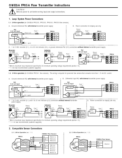
Indicator 4-20 mAC. 1 to 5 VDC recorder (C1), 4 to 20 mA indicator (C2), or ground referenced PLC (C3) connections without internal transmitter power supply *Refer to maximum loop impedance specification for minimum operating voltage requirements (section 10).**1/8A fuse recommended (customer supplied)1.1 2-Wire operation (for OMEGA FP-5200, FP-5300, FP-6000, FP-850X flow sensors). Recorder 1-5 VDCPower *Refer to maximum loop impedance specification for minimum operating voltage requirements (section 10).**1/4 A fuse recommended (customer supplied).1.2 3-Wire operation (for OMEGA FP-2541 flow sensors). This wiring is required for powered flow sensors that consume more than 1.5 mA DC current.Power PLC4-20 mA InputOMEGA FP85A Flow Transmitter InstructionsCAUTION!Remove power to unit before wiring input and output connections.1. Loop/System Power Connections2. Compatible Sensor Connections8. OPTIONS (example)7. CALIBRATE (example)9. Accessories123To return to VIEW:quick pressTo restore original value:quick pressChange:Save:Choose:Press &hold2sContrast FlowTotalizerTotalizerOutputOutputLast calibrationUnit/timebase:h,m,s,dK-factorUnits - label only -4 mA setpoint 20 mA setpointFlow K-factorReturn to VIEW before removing powerPress keys in sequence to continue:A ↓H ↑12To return to VIEW:quick pressTo restore original value:Choose:3Save:Change:quick pressPress keys in sequence to continue:2sPress &holdVIEW=VIEW=Totalizer low= τ=700 ms hi= τ=3 s off= 100 msDisplay avergingFlow displayOutputOutputDecimal postion4 mA adjust 20 mA adjustReturn to VIEW before removing powerA ↓E ↑A.B.C.D.E.F.G.H.A.B.C.D.E.Menu Functions A - H:A.Selects display contrast: 4 levelsB.Sets flow units (gp m) and timebase (gp m ). Flow units label: Aa - Zz, 0 - 9;Timebase options: s=seconds, m=minutes, h=hours, d=days (timebase effects flow display and 4 to 20 mA output)C.Sets flow K-factor: 000.01 to 99999. (see technical notes below)D.Set totalizer units: For label purposes onlyE.Sets totalizer K-factor: 000.01 to 99999. (see technical notes below)F.Sets 4 mA setpoint (4 mA and 20 mA setpoints are reversible)G.Sets 20 mA setpointH.Sets user defined dateTechnical notes:Flow and totalizer K-factors are independent of each other. These K-factors represent the number of pulses generated by the flow sensor for each engineering unit measured (published in flow sensor manual).Menu Functions A - E:A.Selects totalizer reset options: Lock on (enables) or lock off (disables) the VIEW menu totalizer reset security code feature (RST: -- -- -- --).B.Selects display averaging: off = 100ms, low= τ=700ms, hi= τ=3s (also affects 4 to 20 mA output).C.Selects display decimal: **** . to ** .**D.Adjusts 4 mA output: 3.9 to 4.1 mA (overrides 4.00 mA factory calibration)E.Adjusts 20 mA output: 19.8 to 21.0 mA (overrides 20.00 mA factory calibration)O r d e r n o .DescriptionFP85UNM Universal mounting kit, NPT ports FP85UDM Universal mounting kit, DIN portsFP85NM Integral sensor mounting kit, NPT ports FP85DM Integral sensor mounting kit, DIN portsFP8501Integral sensor, 0.5 to 4 inch pipe, Polypropylene body & Titanium rotor pin FP8502Integral sensor, 5 to 8 inch pipe, Polypropylene body & Titanium rotor pin FP8503Integral sensor, 0.5 to 4 inch pipe - PVDF body & Hastelloy C rotor pin FP8501A Integral sensor, 0.5 to 4 inch pipe, Polypropylene body & Titanium rotor pin FP8502A Integral sensor, 5 to 8 inch pipe - Polypropylene body & Titanium rotor pin FP8503A Integral sensor, 0.5 to 4 inch pipe - PVDF body & Hastelloy C rotor pin11. Troubleshooting10. SpecificationsGeneral DataCompatible Sensors:FP-8501, FP-5300, FP-5100, FP-6000, andFP-5200 Series (contact engineering for additional compatible sensors).Display Accuracy:Flow, ±0.1% of readingTotalizers, ±0.03% of reading Enclosure:•Rating:NEMA 4X/IP65•Material:Glass-filled polypropylene •Gasket:Silicone rubber (captive)•Screws:8-32, self-tapping (captive)Display:•Type:8-digit alphanumeric dot matrix •Update rate:Flow=1s, Totalizers=100 mS •Contrast:Variable•Ranges:Flow, 0.01 to 9999.Resettable/permanent totalizers, 0 to 99999999Loop current, 3.90 to 21.00 mAEnvironmentalOperating temperature:-15 to 70 °C (5 to 158 °F)Storage temperature:-15 to 80 °C (5 to 176 °F)Relative humidity:0 to 95%, non-condensingAgency Approvals •CE•Manufactured under ISO 9001Electrical Data Frequency range:0.5 Hz to 500 HzLoop/system power:(2-wire mode) 17 to 30 VDC @ 20 mA max.(3-wire mode) 17 to 30 VDC @ 68 mA max.Sensor power:(2-wiremode)*************.(3-wire mode) 5 VDC @ 20 mA max.Loop:•Impedance: 1 Ω max. @ 17 VDC,300 Ω max. @ 24 VDC,600 Ω max. @ 30 VDC •Accuracy:±0.050 mA •Resolution: 5 µA •Update rate:100 msOutputs:•Current: 4 to 20 mA (adjustable & reversible)•Pulse output:Sensor frequency, optically isolatedopen-collector transistor, max. current sink 10 mA @ 30 VDC(side view)(front view)Dimensions:。
德国GMC-I高美测仪电流传感器 柔性线圈Prosys传感器选型指南

罗氏线圈PRO ~flex 系列订货号型号量程[A] 最大直径 Ø [mm] 带宽 [kHz] 输出信号 [mV/A]接口 供电P-02.710.0ACP 3000/24 30/300/3000 176 20 100/10/1 4mm Battery P-02.712.5ACP 3000/36 30/300/3000 264 20 100/10/1 4mm Battery P-02.712.6ACP 3000/48 30/300/3000 352 20 100/10/1 4mm Battery P-02.713.9ACP 3005/24 30/300/3000 176 20 100/10/1 BNC +3V external or battery P-02.714.0ACP 3005/36 30/300/3000 264 20 100/10/1 BNC +3V external o.battery P-02.714.1ACP 3005/48 30/300/3000 352 20 100/10/1 BNC +3V external or battery P-02.760.0ACP 6000_3/24 60/600/6000 176 20 50/5/0.5 BNC +3V external or battery P-02.760.4ACP 6000_3/36 60/600/6000 264 20 50/5/0.5 BNC +3V external or battery P-02.760.5ACP 6000_3/4860/600/6000352 20 50/5/0.5 BNC +3V external or battery P-02.710.3ACP 3003_3/24 3 x 30/300/3000 176 20 100/10/1 3 x BNC +3V external or battery P-02.713.7ACP 3003_3/36 3 x 30/300/3000 264 20 100/10/1 3 x BNC +3V external or battery P-02.713.8ACP 3003_3/48 3 x 30/300/3000 352 20 100/10/1 3 x BNC +3V external or battery P-02.762.1ACP 6003_3/24 3 x 60/600/6000 176 20 50/5/0.5 3 x BNC +3V external or battery P-02.762.2ACP 6003_3/36 3 x 60/600/6000 264 20 50/5/0.5 3 x BNC +3V external or battery P-02.762.3ACP 6003_3/48 3 x 60/600/60003522050/5/0.53 x BNC+3V external or batteryGMC-I Prosys电流传感器选型指南罗氏线圈MICRO ~flex 系列P-06.460.3ACP 300/2 3/30/300 50 70 500/50/5 4 mm +3V external or battery P-06.460.4ACP 300/3 3/30/300 70 70 500/50/5 4 mm +3V external or battery P-06.460.5ACP 300/4 3/30/300 100 70 500/50/5 4 mm +3V external or battery P-06.690.0ACP 2005/2 20/200/2000 50 100 100/10/1 BNC +3V external or battery P-06.690.1ACP 2005/3 20/200/2000 70 100 100/10/1 BNC +3V external or battery P-06.690.2ACP 2005/4 20/200/2000 100 100 100/10/1 BNC +3V external or battery P-06.690.3ACP 2015/2 20/200/2000 50 1 MHz 100/10/1 BNC +3V external or battery P-06.690.4ACP 2015/3 20/200/2000 70 1 MHz 100/10/1 BNC +3V external or battery P-06.690.5ACP 2015/4 20/200/2000 100 1 MHz 100/10/1 BNC +3V external or battery P-06.600.6ACP 1000/2 10/100/1000 50 20 100/10/1 4 mm Battery P-06.600.7ACP 1000/3 10/100/1000 70 20 100/10/1 4 mm Battery P-06.600.8ACP 1000/4 10/100/1000 100 20 100/10/1 4 mm Battery P-06.600.9ACP 1005/2 10/100/1000 50 100 100/10/1 BNC +3V external or battery P-06.601.0ACP 1005/3 10/100/1000 70 100 100/10/1 BNC +3V external or battery P-06.601.1ACP 1005/4 10/100/1000 100 100 100/10/1 BNC +3V external or battery P-06.600.3ACP 1003_3/2 3 x 10/100/1000 50 100 100/10/1 BNC +3V external or battery P-06.600.4ACP 1003_3/3 3 x 10/100/1000 70 100 100/10/1 BNC +3V external or battery P-06.600.5ACP 1003_3/43 x 10/100/1000100100100/10/1BNC+3V external or battery订货号 型号量程[A] 最大直径 Ø [mm] 带宽 [kHz] 输出信号 [mV/A] 接口 供电AC/DC 电流传感器P RO~flex & MICRO~flex D IN 导轨安装系列P-14.500.3DRP 503/18 3 x 500 132 10 0.667 Screw terminals +12V P-14.500.0DRP 504/18 4 x 500 132 10 0.667 Screw terminals +12V P-14.500.2DRM 503/4 3 x 500 100 10 0.667 Screw terminals +12V P-14.500.1DRM 504/44 x 500100100.667Screw terminals+12VP-12.200.1CP 30 30 25 20 100 4 mm Battery P-12.200.2CP 35 30 25 100 100 BNC Battery P-12.460.0CP 305 30/300 25 20 10/14 mmBattery P-12.230.0CP 41 4/40 25 DC / 15-400Hz Display Battery P-12.480.0CP 410 40/400 25 DC / 15-400Hz Display Battery P-12.601.0CP 1010 100/1000 32 DC / 15-400HzDisplay Battery P-12.600.1CP 1000 1000 32 10 1 4 mm Battery P-12.600.2CP 1005 100/100032 20 10/1 BNC Battery P-12.080.1CP 5_10 5 25 100 1000 - ±10.5 ... ±16VP-12.201.3CP 30_11 30 32 20 100 - +12V P-12.250.0CP 50_10 50 25 100 100 - ±10.5 ... ±16V P-12.390.2CP 150_101502510050-±10.5 ... ±16V订货号 型号量程[A] 最大直径 Ø [mm] 带宽 [kHz] 输出信号 [mV/A] 接口 供电订货号 型号量程[A] 最大直径 Ø [mm] 带宽 [kHz] 输出信号 [mV/A]接口 供电。
STK-CTS P系列电流传感器产品说明书

Sinomags Product DatasheetCurrent SensorProduct Series:STK-CTS/PPart number:STK-25CTS/P6,STK-32CTS/P6Version:V1.2Sinomags Technology Co.,LtdWeb site:CONTENT1.Description (2)2.Electrical data STK-25CTS/P6 (3)3.Electrical data STK-32CTS/P6 (4)4.Frequency band width (5)5.Response time&noise with typical circuit (5)6.Frequency delay performace (6)7.STK-CTS/P6Dimensions&Pins&Footprint (7)1.DescriptionThe STK-CTS/P series current sensor is based on TMR(tunnel magnetoresistance)technology and open-loop design.It is suitable for DC,AC pulsed and any kind of irregular current measurement under the isolated conditions.Typical applications●AC Variable speed drives●Electric welder power supply●Inverter●Switched model power supplies(SMPS)General parameterParameter Symbol Unit ValueWorking temperature T_A℃-40~105Storage temperature T_stg℃-40~105 Mass m g10Remark1:The product will not be damaged when used at105℃Absolute maximum ratinParameter Symbol Unit ValueSupply voltage Vcc V6ESD rating(HBM)U ESD kV4Remark2:the unrecoverable damage may occur when the product works on the conditions over the absolute maximum ratings.Long-time working on the absolute maximum ratings may cause the degradation on performance and reliability. Isolation parameterParamete Symbol Unit Value Comment RMS voltage for AC test50Hz/1min Ud kV4Impulse withstand voltage1.2/50µsÛw kV6Clearance distance(pri.-sec)dCI mm>8Space shortest distanceCreepage distance(pri.-sec)dCp mm>8Shortest distance along the bodyShell material V0according to UL942.Electrical data STK-25CTS/P6Condition:T_A=25℃,Vcc=5VParameter Symbol Unit Min Typ Max Comment Primary nominal current I_pn A25Primary current measuringrangeI_pm A-2525Supply voltage Vcc V 4.755 5.25Current consumption Icc mA510Rated output voltage V_FS V±2(Vout@±I_pn)–VoffInternal output resistance R_outΩ1@Vout Quiescent voltage Voff V 2.48 2.5 2.52Vout@0A Theoretical gain G_th mV/A802V@I_pn Non-linearity Non-L%I_pn0.5±I_pn reaction time t_raµs0.5@10%of I PN Step response time t_resµs1@90%of I PN Delay time t_delayµs1@400kHz-3dB band width BW kHz400Back-end non-RCcircuitNoiseDC~10kHz DC~100kHz Vnoise mVpp1525Accuracy@RT X%of I_pn-11@25℃Accuracy X_TRange%of I_pn-2.5 2.5-40℃~105℃Note:1.Accuracy@RT,X=((Vout@In@25℃)–(G_fit*In+Voff@25℃))/V_FS,Here In is the current test current.G_fit is the normal temperature fitting gain.2.Accuracy,X_TRange=((Vout@In@T_x)–(G_fit@25℃*In+Voff@25℃))/V_FS,The fitting gain of the product at G_fit@25℃is25℃.3.Electrical data STK-32CTS/P6Condition:T_A=25℃,Vcc=5VParameter Symbol Unit Min Typ Max Comment Primary nominal current I_pn A32Primary current measuringrangeI_pm A-3232Supply voltage Vcc V 4.755 5.25Current consumption Icc mA510Rated output voltage V_FS V±2(Vout@±I_pn)–VoffInternal output resistance R_outΩ1@Vout Quiescent voltage Voff V 2.48 2.5 2.52Vout@0A Theoretical gain G_th mV/A62.52V@I_pn Non-linearity Non-L%I_pn0.5±I_pn reaction time t_raµs0.5@10%of I PN Step response time t_resµs1@90%of I PN Delay time t_delayµs1@400kHz-3dB band width BW kHz400Back-end non-RCcircuitNoiseDC~10kHz DC~100kHz Vnoise mVpp1525Accuracy@RT X%of I_pn-11@25℃Accuracy X_TRange%of I_pn-2.5 2.5-40℃~105℃Note:1.Accuracy@RT,X=((Vout@In@25℃)–(G_fit*In+Voff@25℃))/V_FS,Here In is the current test current.G_fit is the normal temperature fitting gain.2.Accuracy,X_TRange=((Vout@In@T_x)–(G_fit@25℃*In+Voff@25℃))/V_FS,The fitting gain of the product at G_fit@25℃is25℃.4.Frequency band widthFig.1the band width of STK-CTS/P series current sensors.The bandwidth of the sensor is in the range of DC~400kHz(-3dB).5.Response time&noise with typical circuitFig.2the step response time of STK-CTS/P current sensors.The light blue is primary current,while the dark blue is output signal of current sensor.。
- 1、下载文档前请自行甄别文档内容的完整性,平台不提供额外的编辑、内容补充、找答案等附加服务。
- 2、"仅部分预览"的文档,不可在线预览部分如存在完整性等问题,可反馈申请退款(可完整预览的文档不适用该条件!)。
- 3、如文档侵犯您的权益,请联系客服反馈,我们会尽快为您处理(人工客服工作时间:9:00-18:30)。
AC/DC and Flexible AC Current Probes and Clamp MetersAC/DC电流探头和钳型表专为与万用表和示波器一起使用而设计,可精确,无干扰地测量AC,DC和复杂电流。
使用先进的霍尔效应技术,AC / DC电流探头可以在DC 至100 kHz的频率范围内以5mA至1000A的1mA分辨率精确测量电流。
这使其成为用于逆变器,开关电源,工业控制器以及其他需要电流测量和/或波形分析的应用的强大工具。
示波器电流探头真有效值钳表万用表电流探头AC/DC 电流传感器和真有效值钳表满足您在汽车和工业应用中需求的解决方案先进的霍尔效应技术采用开环和闭环技术2典型应用:■工业和建筑电气安装测试■UPS和电池充电系统■逆变器、开关电源和工控系统的开关信号波形分析■汽车行业:车载电池的漏电流测量,ECU睡眠模式的侦测及电流的绘制都需要高精度和完美的解决方案。
主要特点:■宽带宽和低相移■瞬时输出和真实RMS读数(钳形表)■电力电子应用的出色噪声抑制■直流自动归零和自动关机■高精度,1mA高分辨率3订货号P-12.200.1P-12.600.1P-12.200.2P-12.460.0P-12.600.2P-12.230.0P-12.480.0P-12.601.0型号CP 30CP 1000CP 35CP 305CP 1005CP 41CP 410CP 1010电流量程30 A1000 A30 A30/300 A100/1000 A4/40 A4/400 A100/1000 A最大直径25 mm Ø32 mm Ø25 mm Ø25 mm Ø32 mm Ø25 mm Ø25 mm Ø32 mm Ø带宽DC ... 20 kHzDC ... 10 kHzDC ... 100 kHzDC ... 10 kHzDC ... 20 kHzDC / 15-400 HzDC / 15-400 HzDC / 15-400 Hz输出信号100 mV/A1 mV/A100 mV/A10/1 mV/A10/1 mV/ADisplayDisplayDisplay接口4 mm4 mmBNCBNCBNC供电BatteryBatteryBatteryBatteryBatteryBatteryBatteryBattery柔性交流电流传感器 - PRO~ex & MICRO~ex当与示波器,记录仪或数据记录仪一起使用时,利用 Rogowski 原理的柔性交流电流探头可用于测量高达 6000A 的交流电流。
柔性探头允许在访问受限的导体上进行电流测量。
探头提供与三个测量范围内的被测电流成比例的瞬时交流输出。
示波器电流探头万用表电流探头满足您在电能质量,能源管理和能源方面的需求的解决方案 各种工业和电力设施应用,使用Rogowski技术的柔性电流探头43 个示波器探头典型应用:■电气设备维护、维修和机器安装时电流测量■中低压配电电流测试■电动机启动瞬间的测量■电力电子设备的开发和维修■分析谐波,功率测量,测量市电和UPS中的峰值负载主要特点:■提供各种头尺寸■易于将探头插入狭窄的空间■宽动态范围和宽带宽■1000V,CAT III,污染等级2,600V CAT IV,污染等级2■2000 小时的电池寿命和外部电源选项■对电流快速变化的出色响应■紧凑轻巧的设计■无磁滞,饱和或非线性5订货号P-06.600.8P-02.710.0P-06.690.0P-02.713.9P-02.760.0P-06.600.4P-02.710.3P-02.762.1型号ACP 1000/4ACP 3000/24ACP 2005/2ACP 3005/24ACP 6000_3/24ACP 1003_3/3 ACP 3003_3/24 ACP 6003_3/24电流量程10/100/1000 A 30/300/3000 A 20/200/2000 A 30/300/3000 A 60/600/6000 A 3x 60/600/6000 A 3x 30/300/3000 A 3x 60/600/6000 A最大直径100 mm Ø176 mm Ø50 mm Ø176 mm Ø176 mm Ø70 mm Ø176 mm Ø176 mm Ø带宽20 kHz 20 kHz 100 kHz 20 kHz 20 kHz 100 Hz 20 Hz 20 Hz输出信号100 / 10 / 1 mV/A 100 / 10 / 1 mV/A 100 / 10 / 1 mV/A 100 / 10 / 1 mV/A 50 / 5 / 0.5 mV/A 100 / 10 / 1 mV/A 100 / 10 / 1 mV/A 50 / 5 / 0.5 mV/A接口4 mm 4 mm BNC BNC BNC BNC BNC BNC供电Battery Battery+3 V external or battery +3 V external or battery +3 V external or battery +3 V external or battery +3 V external or battery +3 V external or batteryFLEXIBLE ACCURATE带DIN导轨外壳的柔性AC探头基于Rogowski原理,它们适用于几百mA到6000A的交流电流测量。
电子设备通常安装在控制柜中,而测量头可以直接通过螺丝安装,也可以通过插座,插头和距离电子设备最远20m的电缆安装,DRP和DRM系列产品提供电压输出信号,该信号与测量的电流成正比。
除单相外,还可提供三个和四个探头的测量系统。
用于DIN导轨安装的柔性交流电流探头DRM和DRP系列产品是采用Rogowski原理的柔性交流电流探头,在DIN导轨安装的外壳中装有三或四通道积分器,用于永久安装。
灵活轻便的测量头可以快速简便地安装,而不会影响主系统。
6显示,存储或数据记录装置F l e x i b l e A C C u r r e n t P r o b e s f o r D I N R a i l M o u n t i n g典型应用:■固定安装和技改升级■能源管理■过程控制■工业厂房的负荷监控 主要特点:■提供多种探头长度和直径■真均方根值(RMS),4至20mA和瞬时输出■多个量程■易于安装订货号P-14.500.2 P-14.500.1 P-14.500.3 P-14.500.0型号DRM 503/4DRM 504/4DRP 503/18DRP 504/18电流量程3x 500 A4x 500 A3x 500 A4x 500 A最大直径100 mm Ø100 mm Ø132 mm Ø132 mm Ø带宽10 kHz10 kHz10 kHz10 kHz输出信号0.667 mV/A0.66 mV/A0.667 mV/A0.667 mV/A接口Screw terminals Screw terminals Screw terminals Screw terminals 供电+12 V +12 V +12 V +12 V7AC 电流互感器交流电流互感器基于交流变压器原理,机械设计尺寸允许在矩形母线或电缆上进行测量,提供各种输出配置,例如电压(AC 或DC)或电流信号(1A 或5A)。
.交流电流互感器适用于从几毫安到3200A的非侵入式交流电流测量,由于采用变压器原理,可以使用交流电流互感器无需任何电池或外部电源即可进行恒流测量,交流电流互感器可以配置一个和多达三个测量档位。
8典型应用:■电能质量应用■监视和控制电机的能耗■能源管理主要特点:■低相移■出色的外部电场抑制■无需电源订货号P-00.440.2P-00.600.1P-00.710.1型号ACP 200 M3ACP 1000 SMACP 3000 H32电流量程200 A1000 A3000 A最大直径Ø15 / 15x17Ø54 / 51x12 / 40x35Ø70 / 100x45 / 120x37带宽10 kHz10 kHz5 kHz输出信号10 mV/A1 mV/A1 mV/A接口4 mm4 mm4 mm供电---定制化解决方案我们的重点是设计,开发和定制用于电流和电压测量以及电参数测量和信号处理的电流探头,钳型表,手持式仪器和系统。
9我们的销售和工程团队拥有非常强大的技术背景,在传感技术,应用和产品方面拥有30多年的经验。
我们的主要市场是汽车,电力公用设施,例如电能质量,能源管理和测试&测量。
我们专门为OEM客户设计定制用于测量电参数的解决方案。
核心优势:■高度灵活,专注并响应客户需求■技术驱动和基于应用开发■与我们的OEM客户一起设计定制产品■基于合同的OEM业务,自有品牌和分销销售■核心技术是霍尔效应,磁通门,Rogowski,磁阻–GMR和AMR关于我们:■GMC-I PROSyS Ltd., 坐落于英格兰西北部, 是德国GMC-I 集团全资子公司。