CR系列电力调整器说明书
Eaton CR型可变电源产品指南说明书
Modular contactors, type CR IEC 60947-4-1 & IEC 61095Product Guide •Full range from 20 A - 63 A •Ac & dc coil type •Contact indication included •Low heat dissipationModular contactors, type CR12Modular contactors, type CR PG03401001U- June 2006 Modularcontactors,typeCR1New range Eaton contactors from 20 A up to 63 AExplanation of Eaton list number system for CR contactors3PG03401001U- June 2006Modular contactors, type CRM o d u l a r c o n t a c t o r s , t y p e C R1CR2011230ADescription Rating ContactsCoil voltage ac Coil voltage dcWidth QPCEatonlist numberContactor 20 A - ac coil 20 A 1 no + 1 nc 24 V ac 18 mm 1CR2011024A Contactor 20 A - ac coil 20 A 1 no + 1 nc 230 V ac -18 mm 1CR2011230A Contactor 20 A - ac coil 20 A 2 nc 24 V ac -18 mm 1CR2002024A Contactor 20 A - ac coil 20 A 2 nc 230 V ac -18 mm 1CR2002230A Contactor 20 A - ac coil 20 A 2 no 12 V ac -18 mm 1CR2020012A Contactor 20 A - ac coil 20 A 2 no 24 V ac -18 mm 1CR2020024A Contactor 20 A - ac coil 20 A 2 no 48 V ac -18 mm 1CR2020048A Contactor 20 A - ac coil 20 A 2 no230 V ac-18 mm 1CR2020230ACR2020024DescriptionRatingContactsCoil voltage acCoil voltage dcWidthQPCEatonlist numberContactor 20 A - ac/dc coil 20 A 1 no + 1 nc 24 V ac 24 V dc 18 mm 1CR2011024Contactor 20 A - ac/dc coil 20 A 1 no + 1 nc 230 V ac 220 V dc 18 mm 1CR2011230Contactor 20 A - ac/dc coil 20 A 2 nc 24 V ac 24 V dc 18 mm 1CR2002024Contactor 20 A - ac/dc coil 20 A 2 nc 230 V ac 220 V dc 18 mm 1CR2002230Contactor 20 A - ac/dc coil 20 A 2 no 12 V ac 12 V dc 18 mm 1CR2020012Contactor 20 A - ac/dc coil 20 A 2 no 24 V ac 24 V dc 18 mm 1CR2020024Contactor 20 A - ac/dc coil 20 A 2 no 48 V ac 48 V dc 18 mm 1CR2020048Contactor 20 A - ac/dc coil 20 A 2 no230 V ac 220 V dc18 mm 1CR2020230CR2540230ADescriptionRatingContactsCoil voltage acCoil voltage dcWidthQPCEatonlist numberContactor 25 A - ac coil 25 A 2 no + 2 nc 24 V ac 36 mm 1CR2522024A Contactor 25 A - ac coil 25 A 2 no + 2 nc 230 V ac 36 mm 1CR2522230A Contactor 25 A - ac coil 25 A 3 no 24 V ac 36 mm 1CR2530024A Contactor 25 A - ac coil 25 A 3 no 230 V ac 36 mm 1CR2530230A Contactor 25 A - ac coil 25 A 4 nc 24 V ac 36 mm 1CR2504024A Contactor 25 A - ac coil 25 A 4 nc 230 V ac 36 mm 1CR2504230A Contactor 25 A - ac coil 25 A 4 no 12 V ac 36 mm 1CR2540012A Contactor 25 A - ac coil 25 A 4 no 24 V ac 36 mm 1CR2540024A Contactor 25 A - ac coil 25 A 4 no 48 V ac 36 mm 1CR2540048A Contactor 25 A - ac coil 25 A 4 no230 V ac36 mm 1CR2540230ACR2504024DescriptionRatingContactsCoil voltage acCoil voltage dcWidthQPCEatonlist numberContactor 25 A - ac/dc coil 25 A 2 no + 2 nc 24 V ac 24 V dc 36 mm 1CR2522024Contactor 25 A - ac/dc coil 25 A 2 no + 2 nc 230 V ac 220 V dc 36 mm 1CR2522230Contactor 25 A - ac/dc coil 25 A 3 no 24 V ac 24 V dc 36 mm 1CR2530024Contactor 25 A - ac/dc coil 25 A 3 no 230 V ac 220 V dc 36 mm 1CR2530230Contactor 25 A - ac/dc coil 25 A 4 nc 24 V ac 24 V dc 36 mm 1CR2504024Contactor 25 A - ac/dc coil 25 A 4 nc 230 V ac 220 V dc 36 mm 1CR2504230Contactor 25 A - ac/dc coil 25 A 4 no 12 V ac 12 V dc 36 mm 1CR2540012Contactor 25 A - ac/dc coil 25 A 4 no 24 V ac 24 V dc 36 mm 1CR2540024Contactor 25 A - ac/dc coil 25 A 4 no 48 V ac 48 V dc 36 mm 1CR2540048Contactor 25 A - ac/dc coil 25 A 4 no230 V ac 220 V dc36 mm 1CR25402304Modular contactors, type CR PG03401001U- June 2006M o d u l a r c o n t a c t o r s , t y p e C R1Day / night contactors do have a manual override function, which enables the user to bring the contactor in either a forced "ON" or "OFF" position.The contactor can only be brought into the forced "ON" position when it is de-energised. When the contactor is energised the operation will return into the normal/automatic position.Can be connected at the right-side of the contactor.To be installed after every 2 contactors.Example: contactor + contactor + spacer + contactor, etc.CR4030024DescriptionRatingContactsCoil voltage acCoil voltage dcWidthQPCEatonlist numberContactor 40 A - ac/dc coil 40 A 2 nc 230 V ac 220 V dc 54 mm 1CR4002230Contactor 40 A - ac/dc coil 40 A 2 no 24 V ac 24 V dc 54 mm 1CR4020024Contactor 40 A - ac/dc coil 40 A 2 no 230 V ac 220 V dc 54 mm 1CR4020230Contactor 40 A - ac/dc coil 40 A 3 no 24 V ac 24 V dc 54 mm 1CR4030024Contactor 40 A - ac/dc coil 40 A 3 no 230 V ac 220 V dc 54 mm 1CR4030230Contactor 40 A - ac/dc coil 40 A 4 no 12 V ac 12 V dc 54 mm 1CR4040012Contactor 40 A - ac/dc coil 40 A 4 no 24 V ac 24 V dc 54 mm 1CR4040024Contactor 40 A - ac/dc coil 40 A 4 no 48 V ac 48 V dc 54 mm 1CR4040048Contactor 40 A - ac/dc coil 40 A 4 no230 V ac 220 V dc54 mm 1CR4040230CR6320230DescriptionRatingContactsCoil voltage acCoil voltage dcWidthQPCEatonlist numberContactor 63 A - ac/dc coil 63 A 2 no 230 V ac 220 V dc 54 mm 1CR6320230Contactor 63 A - ac/dc coil 63 A 4 no 24 V ac 24 V dc 54 mm 1CR6340024Contactor 63 A - ac/dc coil63 A 4 no230 V ac 220 V dc54 mm 1CR6340230CRM2540230ADescriptionRatingContactsCoil voltage acWidthQPCEatonlist numberDay / night contactor - ac coil 20 A 2 no 230 V ac 18 mm 1CRM2020230A Day / night contactor - ac coil 25 A 4 no230 V ac36 mm 1CRM2540230ACRA611Auxiliary contactsDescriptionContactconfigurationRatingWidthQPCEatonlist numberAuxiliary contact for contactors 1 no + 1 nc 6 A 9 mm 1CRA611Auxiliary contact for contactors 2 no 6 A 9 mm 1CRA620CRC63Terminal covers (sealable)DescriptionType contactorWidthQPCEatonlist numberTerminal cover, sealable For 20 A 18 mm 10CRC20Terminal cover, sealable For 25 A 36 mm 10CRC25Terminal cover, sealable For 40 / 63 A 54 mm 10CRC63CRSSpacerDescriptionWidthQPCEatonlist numberSpacer for contactors 9 mm 10CRS5PG03401001U - June 2006Technical details, Eaton contactorsTechnical details, Eaton contactors2T e c h n i c a l d e t a i l s , E a t o n c o n t a c t o r s2Contactors type CR, dimensional drawingsContactors, type CR40, CR63Day/Night contactors, type CRM20, CRM25Auxiliairy contactSpacer6Technical details, Eaton contactors PG03401001U - June 2006T e c h n i c a l d e t a i l s , E a t o n c o n t a c t o r s2Contactors type CR, technical detailsProductsContactorsAux. contactRating20 A25 A40 A63 A6 AGeneralStandardsIEC 60947-4-1, IEC 61095IEC 60947-5-1Nominal operating voltage 1-phase U e 1-ph.230 V 230 V 230 V 230 V 230 VNominal operating voltage 3-phase U e 3-ph.400 V400 V 400 V Overvoltage protection on coil430 V (*5)430 V (*5)430 V 430 V Mechanical endurance (switching cycles) 3.000.000 3.000.000 3.000.000 3.000.000 3.000.000Protection class (acc. DIN 40 050, IEC 529)IP20IP20IP20IP20IP20Permissible ambient temperature -5…+55 °C -5…+55 °C -5…+55 °C -5…+40 °C -5…+55 °C Storage temperature-30…+80 °C-30…+80 °C-30…+80 °C-30..+80 °C-30…+80 °C Contact ratingRated insulation voltage U i 440 V 440 V 500 V 500 V 500 V Frequency50/60 Hz 50/60 Hz 50/60 Hz 50/60 Hz‘50/60 Hz Rated impulse withstand voltage U imp 4 kV 4 kV 4 kV 4 kV 4 kV Rated thermal currentI th 20 A 25 A 40 A 63 A 6 AAC1 / AC7a Rated operational currentI e 20 A 25 A 40 A 63 A AC1 / AC7a Operational power rating at U e = 230 V ac P max 4 kW 9 kW 16 kW 24 kW AC1 / AC7a Operational power rating at U e = 400 V ac P max 16 kW 26 kW 40 kW AC3 / AC7b Operational power rating at U e = 230 V ac P max 1,3 kW (*1)2,2 kW 5,5 kW 8,5 kW AC3 / AC7b Operational power rating at U e = 400 V ac P max 4 kW11 kW 15 kW DC1 Rated thermal current at U e = 24 V dc I e 20 A 25 A 40 A 63 A DC1 Rated thermal current at U e = 110 V dc I e 1 A 2 A 4 A 4 ADC1 Rated thermal current at U e = 220 V dc I e 0,5 A 0,5 A 0,8 A 0,8 A DC1 Rated thermal current at U e = 24 V dc (2-poles in series)I e 20 A 25 A 40 A 63 A DC1 Rated thermal current at U e = 110 V dc (2-poles in series)I e 3 A 4 A 10 A 10 A DC1 Rated thermal current at U e = 220 V dc (2-poles in series)I e1,5 A1,5 A6 A6 ADC1 Rated thermal current at U e = 24 V dc (3-poles in series)-25 A 40 A 63 A DC1 Rated thermal current at U e =110 V dc (3-poles in series)- 6 A 30 A 35 A DC1 Rated thermal current at U e = 220 V dc (3-poles in series)-2,5 A20 A30 AElectrical enduranceMaximum operating cycles at AC1 / AC7a application 200.000 x 200.000 x 100.000 x 100.000 x Maximum operating cycles at AC3 / AC7b application 300.000 x 500.000 x 150.000 x 150.000 x Maximum operating cycles at AC5a application 100.000 x 100.000 x 100.000 x 100.000 x Maximum operating cycles at AC5b application 100.000 x (*2)100.000 x (*2)100.000 x (*3)100.000 x (*4)Maximum operating cycles per hour 600 x 600 x 600 x 600 x 600 xPower dissipation per contact at In 1,7 W 2,2 W 4 W 8 W Maximum back-up fuse25 A gL35 A gL63 A gL80 A gL7PG03401001U - June 2006Technical details, Eaton contactorsT e c h n i c a l d e t a i l s , E a t o n c o n t a c t o r s2ProductsContactorsAux. contactRating20 A25 A40 A63 A6 AOperating coil (for combined ac/dc types only - CR.....)Coil inrush power (for all voltage ratings)2,5 W 3 W 5 W 5 W Coil consumption (for all voltage ratings)2,5 W 3 W 5 W 5 W Closing delay 15-25 ms 10-20 ms 15-20 ms 15-20 ms Opening delay10 ms50-80 ms35-45 ms35-45 msOperating coil (for ac types only - CR.....A)Coil inrush power (for all voltage ratings)13 W / 15 VA 17 W / 27 VA Coil consumption (for all voltage ratings)1,9 W / 3 VA 1 W / 2.6 VA --Closing delay 15-25 ms 10-20 ms --Opening delay20 ms20 ms--DimensionsWidth 18 mm 35 mm 54 mm 54 mm 9 mm Height 85 mm 85 mm 85 mm 85 mm 85 mm Depth60 mm60 mm60 mm60 mm60 mmTerminals for main & auxiliairy contactsTerminal capacity - fine stranded wire 1.....6 mm 2 1.....6 mm 2 1.....16 mm 2 1.....16 mm 2 1....2,5 mm 2Terminal capacity - solid wire 1.....10 mm 2 1.....10 mm 2 1.....25 mm 2 1.....25 mm 2 1....2,5 mm 2Terminal screw sizeM3,5M3,5M5M5M3Terminal screw head type (Pozidrive)PZ Size 1PZ Size 1PZ Size 2PZ Size 2PZ Size 1Maximum torque1,2 Nm1,2 Nm2,0 Nm2,0 Nm0,8 NmTerminals for operating coilsTerminal capacity - fine stranded wire 1.....2,5 mm 2 1.....2,5 mm 2 1.....2,5 mm 2 1.....2,5 mm 2Terminal capacity - solid wire 1.....2,5 mm 2 1.....2,5 mm 2 1.....2,5 mm 2 1.....2,5 mm 2Terminal screw sizeM3M3M3M3Terminal screw head type (Pozidrive)PZ Size 1PZ Size 1PZ Size 1PZ Size 1Maximum torque0,6 Nm0,6 Nm0,6 Nm0,6 NmRemarks:*1) Only applicable for normally open contact(s)*2) At 1,5 kW *3) At 3 kW *4) At 5 kW*5) For CR…. types only (combined ac/dc types), NOT for CR....A types8Technical details, Eaton contactors PG03401001U - June 2006T e c h n i c a l d e t a i l s , E a t o n c o n t a c t o r s2Contactors type CR, lamp load tableLightingLamp load (Watt)Maximum number of fittings per contactor typeTypeCR 20CR 25CR 40CR 63Incandescent lamp15861102284802552721802904032501221956021338613075172669104100132052781508133452200610263925058203130046172650024101510001257Energy saving lamp34252831205425283120742528312093645721041133416594153037598520293657822328355681Fluorescent lamp - conventional supplySingle fitting - Uncompensated (inductive)182224901402422249014036172065955814174570Single fitting - Compensated (capacative)18784873247848733678487358453147Double fitting - Series compensated2 x 1830401001502 x 242431781182 x 36172465952 x 5810144060Fluorescent lamp - HF electronicSingle fitting - HF Electronic182531497124182235503614172739588101623Double fitting - HF Electronic2 x 181******** x 2491117252 x 367813192 x 5845811Compact fluorescent lampConventional supply53848771217273454869212642671117213555Electronic supply5394978124739497812493038619611253150799PG03401001U - June 2006Technical details, Eaton contactorsT e c h n i c a l d e t a i l s , E a t o n c o n t a c t o r s2LightingLamp load (Watt)Maximum number of fittings per contactor typeTypeCR 20CR 25CR 40CR 63High pressure mercury vapour lampUncompensated5014183855801013294212579202925045101540023710Parallel compensated504531478045274112534223325012121840011913Halogen metal vapour lampUncompensated35182243607010122332150571218250347104003369Parallel compensated3556365070231825150111115250-169400-168Low pressure sodium vapour lampUncompensated1822277190357923305579233090451419135341013180341013Parallel compensated1867446635111116551111169011812135--47180--47High pressure sodium vapour lampUncompensated15056172225034101340022681000-133Parallel compensated150111116250-1610400--461000--23General remarks:1) In case a 4-pole contactor is used (3 ph. + neutral) the above mentioned quantity of lamps need to be multiplied by 1,5 to obtain the maximum quantity of fittings for the contactor. The total quantity of fitting need to be split equally across the 3 poles.2) In case multiple contactors are installed in one panel it is required to multiply the above mentioned fittings by the applicable load factor according the IEC 60439-1.3) It is recommended to install one spacer between each 2 contactors installed (eg contactor, contactor, spacer, contactor, etc.).+61 2 9693 9388+61 2 9693 1258************************************(toll-freeline)*************************************************************。
CR1300说明书-中性

注意:安装、运行、维护或检查之前要认真阅读本说明书。
设备的设计、安装、调试和运行,必须由经过培训的专业人员来进行;在工作过程中,必须遵循安装检修中所有的规定,否则可能造成严重的人身伤害或重大财产损失。
1. 注意事项(1)操作前确保电源完全切断。
(2)设备禁止安装在易燃物上,否则有发生火灾的危险。
(3)主回路接线后,应对裸露的接线端子进行绝缘处理,否则会有触电的危险。
(4)通电情况下,不要用潮湿的手操作设备,否则有触电危险。
(5)设备在通电过程中,请勿打开面盖及进行配线作业,必须在关闭电源10分钟后,方可实施配线或检查。
(6)必须具有专业资格的人员才能进行配线作业,严禁将任何导电物遗留在设备内,否则有触电或造成设备损坏的危险。
(7)存贮时间超过2年以上的设备,上电时应先用调压器逐渐升压,否则有触电和爆炸的危险。
(8)严禁将接线端子中R、S、T以外的端子接上交流380V电压,否则有损坏财物的危险。
(9)如果设备有损伤或部件不全时,请不要安装运转,否则有发生火灾或导致人员受伤的危险。
(10)安装时,应该在能够承受设备重量的地方进行安装,否则掉落时有致人受伤或损坏财物的危险。
2.安全须知和维护(1)安全须知因设备工作在380V的三相交变电压,机箱内外线路电压相当高,在设备上电运行时,身体任何部位不可贴近设备的输入输出端子处。
即使感应加热设备处于不工作状态,输入及输出接线端子仍然可能带有威胁电压。
如需查看设备内部状况或检修,必须断开电源,为安全起见应断电几分钟后确保设备无电流时方可开箱检修。
(2)维护为了确保感应加热电源正常运行,延长设备运行寿命,需要对设备进行定期维护,维护的内容如下表所示:检查项目内容温度/湿度确定环境温度在-20℃~+40℃,相对湿度在20%~90%确认设备内无油雾和粉尘、无凝露油雾和粉尘存储环境无腐蚀性气体、液体感应加热设备检查设备有无异常发热、有无异常振动风扇确定风扇运作正常、无杂物卡住等情况输入电源确定输入电源的电压和频率在允许的范围内线圈检查线圈是否正常,无发黄则表明无油雾和粉尘、无凝露表2-1 维护项目鉴于设备工作过程易摄入粉尘,特别在风扇模块,尽量避免因粉尘积压而影响散热导致机箱内部温度过高造成不良效果,为延长设备寿命,建议定期为风机及散热器除尘,不超过两个月一次,定期为机箱内部器件除尘,不超过一年一次。
三相电力调整器(调功器)使用说明书
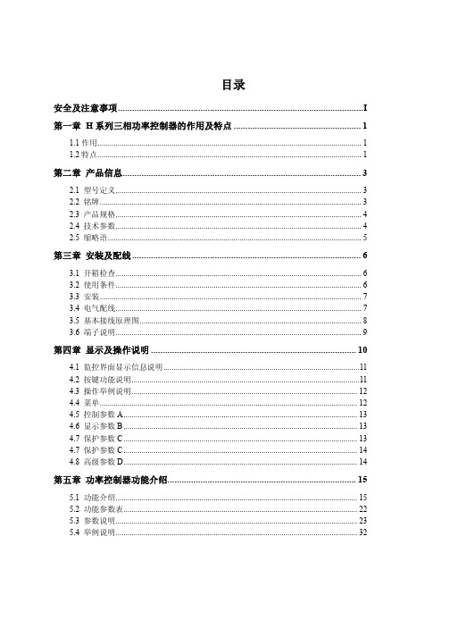
目录安全及注意事项 (I)第一章H系列三相功率控制器的作用及特点 (1)1.1 作用 (1)1.2 特点 (1)第二章产品信息 (3)2.1 型号定义 (3)2.2 铭牌 (3)2.3 产品规格 (4)2.4 技术参数 (4)2.5 缩略语 (5)第三章安装及配线 (6)3.1 开箱检查 (6)3.2 使用条件 (6)3.3 安装 (7)3.4 电气配线 (7)3.5 基本接线原理图 (8)3.6 端子说明 (9)第四章显示及操作说明 (10)4.1 监控界面显示信息说明 (11)4.2 按键功能说明 (11)4.3 操作举例说明 (12)4.4 菜单 (12)4.5 控制参数A (13)4.6 显示参数B (13)4.7 保护参数C (13)4.7 保护参数C (14)4.8 高级参数D (14)第五章功率控制器功能介绍 (15)5.1 功能介绍 (15)5.2 功能参数表 (22)5.3 参数说明 (23)5.4 举例说明 (32)第六章故障处理及保养维护 (35)6.1 故障处理 (35)6.2 保养维护 (35)第七章通信说明 (37)7.1 通讯数据读写 (37)7.2 协议内容 (37)7.3 总线结构 (37)7.4 通讯帧结构 (38)7.5 MODBUS通讯协议 (38)第八章售后服务 (40)附表一 (41)I安全及注意事项危险:由于没有按要求操作,可能造成设备严重损坏或人员伤亡的场合。
注意:由于没有按要求操作可能造成中等程度伤害或轻伤,或造成物质损失的场合。
本指示对于正在工作的功率控制器非常重要,忽略这些指示可能对您造成身体损害甚至导致死亡。
○1安装控制器应安装在金属等不可燃物上,否则有发生火灾的危险。
不要安装在含有爆炸性气体的环境里,否则有引发火灾的危险。
不要把易燃、易爆物品放在控制器附近,否则有引发爆炸的危险。
不要将螺钉、垫片等金属物掉进控制器内部,否则有引发爆炸和发生火灾的危险。
自-SUG61005C6KV三相五线产品说明书
雷击浪涌发生器LIGHTNING SURGE GENERATORSUG61005C使用说明书Prima上海普锐马电子有限公司使用注意事项雷击浪涌发生器在工作时产生高能量(高电压、大电流)的浪涌。
为安全起见,请阅读本说明书,并正确使用本设备。
使用中请注意以下几点:ﻩ(1) 当手潮湿或相对湿度超过75%时,不要使用本设备。
(2) 因为有高压脉冲加到输出接线端子(如,2Ω,500Ω,L1,L2,L3等端口),如果改换接线,务必要在确认高压电源处于断开状态才能进行。
(3) 尽管操作本设备时,很少遇到电击,但为安全起见,在操作时不要进食,防止偶然因电击引起的进食阻塞。
(4) 用本设备做试品的抗干扰试验时,要注意必须将本设备的接地端子与大地接在一起。
ﻩ(5) 本设备是利用高压水银开关来产生高压脉冲,严禁在设备倾斜状态下,进行试验。
ﻩ(6) 内带高压,请勿随意拆卸或敞开机壳工作。
(7)由于打开仪器上的试品电源开关时有可能会引起外围电网的漏电保护开关或空气开关跳闸。
解决办法有两种:一是避开有漏电保护开关地方;二是试品电源输入处加功率与仪器相匹配的隔离变压器。
使用说明书一:适用范围SUG61005C是严格按照国际电工委员会IEC颁布的IEC61000-4-5和IEC801-5标准制造,适用于国标GB/T17626.5,其性能指标符合标准相应要求。
SUG61005C是用于评定电气和电子设备电源线和内部连线在经受来自开关切换及自然界雷击所引起的高能量瞬变干扰时的性能提供一个共同依据。
二:SUG61005C简介1主要技术指标雷击浪涌输出波形●电压波:1.2/50μs(波形发生器输出开路时)●电流波:8/20μs (波形发生器输出端短路时)●电压波输出阻抗:2Ω±10%(另设有“500Ω”的端子,专门提供对绝缘耐压试验的用户要求)●综合波输出电压波形峰值:0~6kV输出电流波形峰值:0~3kA●击打方式同步:相位0-360℃连续可调。
BLR-CX电力因数调节器操作和启动手册说明书
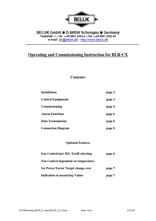
BELUK GmbH ! D-86956 Schongau ! GermanyTaubenstr. 1 " Tel. ++49 8861 2332-0 " Fax ++49 8861 2332-22e-mail: - http://www.beluk.deOperating and Commissioning Instruction for BLR-CXContents:page2 Installationpage2EquipmentsControl4 Commissioning page6pageAlarmFunctions6pageTransmissionData8Diagram pageConnectionOptional FeaturesFan Control incl. H/L-Tariff selecting page 6Fan Control dependent on temperaturefor Power Factor Target change over page 7Indication of measuring Values page 7InstallationAs with all electrical equipment, the appropriate specifications governing electrical installation must be followed when power factor correction equipment is installed. When removing the front nameplate to adjust the function switch and DIP switches, always ensure that your body is not carrying any electrostatic charge. This can be accomplished by simply touching an earthed object, such as the switchboard metal casing to dissipate any electrical charge before removing the cover plate.1 Check that the measurement and control voltage, supply frequency and current transformer rating comply with theratings given on the back of the relay.2 Mount the relay in the switch panelby means of two fixing bolts3 Connect up in accordance with the wiring diagram. Pay special attention to the cross section size of the C.T.connections. We recommend for runs up to 10 metres 2,5 mm2 cross section. An integrated voltageobservation with regard to the supply voltage in BLR-CX guarantees a safety-disconnection of the capacitors incase of excess voltage < 70 % of mains voltage. It must be ensured, that supply voltage is taken from the identical phase as control voltage for the contactors. Please use specified tool for wiring into the spring terminals. Steelcover on the rear of the relay must be earthed.4 Current path of the regulator is designed for current transformers either for5 A or 1 A secondary coil as well.Selectable c.t. ratio up to 4000 max. C.t.-ratio setting is only possible for regulators with option M, excludingly(Regulators with additional energy data indications).Control EquipmentsBehind the removable nameplate there are a multifunction switch (H3) and 2 pushbuttons (+/-) available.At option “L” (fan control) there are 2 additional DIP switches (S1/S2) fitted for selecting 4 temperature threshold levels.At option “M” (Multimeter Functions) 2 additional keys are integrated on front facia for polling off data.Selecting regulators parameter will be done by means of the +/- pushbuttons with reference to the preselected step of the multifunction switch (H3). Preselected parameters ex work facilitates commissioning the regulatorAll regulators are preset at the multifunction switch (H3) to the following parameter es work:Multifunction Switch (H3)0 Any control out of order. Energized steps, if any, will be disconnected after 20 sec. automatically. Selecting ofa threshold level in the range of 10….60 % with reference to the recorded first value of each capacitor step(equal 100 %) at commission of the plant. Preset value ex work: 50 %. Display indicates “OFF” alternating with “50”1 p.f. target set, selectable in the range of 0,70 lag …1…0,90 lead;preset to cos ϕ = 1,002 Switching time delay, selectabel from 5 sec ... 1200 sec. Pushing button + or – for longer than 2 sec. enables rapidselection.Preset delay ex work: 40 sec.3 Fully automatic control of compensation plant. Display indicates the current power factor with either I forinductive or c for capacitive load (reprinted each 3 sec.) A flashing dot in display above the signs either + or –signals, that the regulator is selecting a suitable capacitor, if available, with regard to the reactive power deviation current cos ϕ indication each 3 sec.Energy data available with option M excludingly.operation4 ManualManual operation is possible with measuring voltage > 50 V, excludingly, by alternating pushing either the + or the – button, steps will be activated or deactivated, respectively, to the preset switching time delay in position 2,accordingly. Letter H will be displayed alternating with the current p.f. (1 sec/ 5 sec)5 Selection of Step LimitationStep limitation in accordance to the available outputs referring to type of relay CX 04, CX 06, CX 08 or CX 12.Limitation will be displayed e.g. “CL 12”. Do not exceed the max. available outputs as far as alarm will betriggered.6 Automatic display of failed CapacitorsIndication of either failed capacitor steps or unengaged outputs. Indication of e.g. “Cd 05” alternating with “Cd 09” indicates, that steps 5 and 9 are failing. “Alarm” (AL_ _) will be triggered synchronously. To reset any alarm press button + and – for longer than 20 sec. “Cd 0” signals, that no step fails. Automatic control is active all the time!7 The number of switchingThe number of switching operations per each contactor has made is shown in the display, e.g. “OC 4” for 2 sec., then “248”. This indicates, that contactor no. 4 has completed 248 switching operations. Other contactors can be selected by using the +/- buttons. Only every 10 switching operations the micro processor stores the data. The stored data of all steps can be cancelled by depressing the +/- buttons together for a time longer than 20 sec.Automatic control is active all the time!8 Indication of Step SizesThe value indicated on display is proportional to the step size, but not calculated in kvar, as far c.t.-ratio isunknown. It will be displayed e.g. “CC 10” for the 10th step, followed by 2 numbers e.g. “L 74” and “F 84”.Value “F” stands for the f irst sensed capacitor size during commissioning and “L” for the l ast value after, let´s say several months or years. This is to recognize loss of capacity, if any. If the selected threshold level in pos. 0, will be decreased due to failed capacitor or blown up fuses, the regulator eliminates this step from control procedure and triggers alarm “AL”, shown in display. The data per each step may be polled off by means of either + or – button.To reset the stored data enables by pushing both buttons + and – together for longer than 20 sec. The regulator starts to come to know each step from the very beginning. Automatic mode is still active in the background.CX-regulators fitted with option “M” (Indication of energy data) displays the sensed capacitor sizes in real kvar at correct c.t. setting (see page 5).9 Selecting Mode of AlarmSelection by means of the push buttons +/-.Any alarm function is deactivated in selecting “A__0”, no alarm indication will appear. Automatic reset of any triggered alarm if, e.g. the regulator is able to achieve the preset power factor target again or after any change of switching direction, up/down, in selecting “A__1”.Once a triggered alarm will be stored until any manual confirmation in selecting “A__2”.Reset possible with “A__3”, excludingly.To reset any triggered alarm, caused either by control procedure (triggered by passing 75 times preset switching time delay) or by temperature, enables in selecting “A__3” and pushing button + longer than 5 sec. It will be confirmed by “ArES” in display. Afterwards select requested alarm mode again. Any triggered alarm, caused by failed steps, is ressettable in position 6 of the multifunction switch (H3), excludingly,at preset alarm mode “A__2”.(“AL” will be displayed in case of any triggered alarm).A Selection of a 2nd Power Factor TargetOption “L” 2nd p.f. target will be activated by signal voltage 150-240 V AC on terminals NT/NT1.Option “LT” 2nd p.f. target will be activated automatically in case of temperature will exceed 57° CB Selection of an asymmetrical Switching Time Delay.Selectable range of an asymmetric factor: 1…99 by means of pushing the button + or -. Displaying e.g. “Y_10”multiplies the preselected switching time (pos. 2) with factor 10 for disconnecting steps (rapid in, slow out; slow in, rapid out on request). Preset factor ex word = “1”, means symmetrical switching time delay for both directions.C Selection of a Lock Time at each Change of Switching Direction up/downAn included variable load reversal lock-out time is activated when switching direction changes from “up” to“down” or conversely. Displaying e.g. “L_30” means a lock time of 30 sec. becomes effective. This lock time will be added to the preset switching time delay ex pos. 2. This enables to reduce the switching operations at rapid changing loads. Selectable range of lock time = 1…254 sec.;preset time ex work: 30 sec.D Selection of C.T.Ratio (only adjustable with option “M”)“_not”DisplayindicatesE Selection of V.T. Ratio (only adjustable with option “M”)“_not”indicateDisplayF Selection of Switching Program by means of pushing button + or -.After any amendment re-energize the regulator (brief interruption of supply voltage)Displaying “Auto”: Fully automatic recognition of each capacitor size without fixed program intelligent selection of the suitable capacitor to achieve the preset power factor target with the minimum of switching operations.2-phase connection L2/L3.Displaying “1 1 1 1”: Fully automatic recognition of each capacitor size. Linear switching program up 1….12 and down 12….0 means FILO/LIFO (first in last out / last in first out). 2-phase connection L2/L3.Displaying “Eaut”: identical to “Auto”, however 1-phase connection L1/NDisplaying “E111”: identical to “1111”, however 1-phase connection L1/NPreset ex work: “Auto”Commissioning1 Apply the supply-, measurement- and control-voltages. Connect the current transformer, and remove any shortcircuit link. If measurement voltage is taken from 1 phase against neutral modification must be ensured in positionF of the multifunction switch (H3) followed by a voltage reset of the supply voltage.Indication “I—O” : no current flowing, resp.: <10 mA of secondary c.t. current. If any capacitors had beenenergized before, these steps will be disconnected at once after 5 minutes (possible at parallel operation of capacitor banks). If regulator is set to manual mode, any energized steps “stand by” all the time.Indication “U—0” measuring voltage is below 50 V or not connected.Regulator will start to control, if measuring-voltage is 50 V and reactive component of current 10 mA at least.If measuring voltage decreases below 50 V any energized steps will be switched off at once after delay of 2 sec.indipendent on either automatic or manual mode.2 Ex work preset parameters are:Power factor target = 1; switching time delay 40 sec.; step limitation to regulator´s maximum; alarm mode = 1;asymmetrical switching time factor = 1; load reversal lock tim = 30 sec.; c.t.-ratio = 100; v.t.-ratio = 1.0; switching mode = Auto with 2-phase measuring voltage L2/L3. Any modifications, if requested, may be done viamultifunction switch (H3) and push buttons + or -, as described. Amendments of parameters will be indicated on display.Attention: c.t.-ratio and v.t.-ratio exclusive adjustable with option “M”!The selected parameters will be stored in the regulator, if multifunction switch will be set back into pos. 3again, only.3 Ensure, that multifunction switch (H3) is set to pos. 3 (Automatic mode)4 No volt release lock time of 90 sec. must be passed, before regulator starts to control. During this period steps willnot be activated.5 Check preset power factor target in pos. 1 and select, if requested.6 Check preset switching time delay pos. 2 and select, if requested.7 Check preset step limitation and adapt to the real number of connected capacitors in pos. 5. If any control output ofthe regulator remains unengaged, it will be recognized. The regulator tests each free output 3 times to ensure it isunengaged and will lock this step for 1 day at least, until a voltage interruption or after reset of “CD” in pos.6. Then these steps will be checked again 3 times each. If there are still “failed steps” detected, they will be recorded in pos. 6;alarm will be triggered.8 Check preset alarm mode and select in pos. 9, if requested.9 Set back the multifunction switch into pos. 3.10 Display indicates the current power factor cos phi e.g. “i 0.87” for inductive or “c 0.94” for capacitive load.11 At correct wiring after the no volt release lock time and inductive load a dot in the display at sign “+” will flash.12 The regulator starts to energize step by step in the rhythm of selected switching time delay in order to achieve thepower factor target. LED`s signal activated steps. Each step must influence the current cos phi. Is there a digitaldeviation of the current power factor compaired with the target, dot at sign “+” will flash in case of p.f. is below or dot at sign “-“ will flash in case of p.f. is above the target.13 At BLR-CX it is not necessary to preset any C/k-value (threshold level when to start to switch in/out a step), as farthe step sizes will be sensed automatically. The regulator does not follow up a fixed switching program; it willselect a suitable capacitor, if recorded already, in order to achieve the target. During the daily routine all capacitors will be stored with regard to its size in numbers proportional to the capacitance (see pos. 8 of H3). There is noindication in kvar , as far the c.t. is unknown. (Exception at option M). At use of equal sized capacitors theregulator distributes the switching operations equally to the capacitors as much as possible. For special applications there is a fixed switching program available in the ratio 1:1:1….:1 in pos. F of H3.14 It may happen, that one of the dot + or – are flashing steadily and the regulator will not switch on/off any step asfar it is not able to find a suitable step size with reference to the deviation from the target p.f. If p.f. is digitalidentical with the target, no dot is flashing.15 In case of no existing load a first check of the capacitor bank may be possible in manual mode in pos. 4 at themultifunction switch (H3) by using push button + for switching on capacitors. Ensure, that measuring voltage is >50 V AC. In this mode there is no automatic sensing of the step sizes given. Returning back to pos. 3 then theregulator must disconnect all steps automatically; in this mode the regulator is able to recognize the sizes,excludingly (see item 13).Once the required settings or alterations have been made, set function switch (H3) to position 3 “automatic” and replace the front cover plate, so as to inhibit unauthorized interference with relaysettings.Alarm Functions1 Power Factor Alarm (Display shows: “AL”)If the predetermined power factor is not abtained in case of insufficient capacitance, the alarm signal is triggeredafter elapse of 75 x the selected step switching time, valid for both directions lead and lag. If the set target p.f. isstill surpassed due to overcompensation (welded contacts) after elapse of 75 x the selected step switching time, this alarm will be triggered, “AL” displayed. To reset any triggered alarm will be possible in pos. 9 of the multifunction switch (H3) in mode A__3 (see item 9, page 3)2 Alarm will be triggered as well, if the regulator has detected failed step(s). “AL_ _” will be displayed alternatingwith other functions (cos phi) each 5 sec. Reset is possible in pos. 6 of H3 (see page 2).3 If supply voltage fails, there is no indication in display, contact at terminalsM – MO will close and M – MS opens for external use; switching rate: 3 A at 250 V ACData TransmissionBELUK-software “WINBSTO” enables to indicate and recording of power factor, operation cycles, any triggered alarm, signed with clock and date on PC for purposes of analysis. Each switching operation of the regulator are accompanied with 2 telegrams via TTL-interface (14-pole plug on the rear of casing), one before and one after switching procedure. This enables to analyze the compensation effect per each step with regard to the influence of the power factor. Storing data on PC requests a data cable with integrated converter TTL/RS232 for transmitting the data to the PC (extra equipment- length 0,2 m – No.8). Furtheron it is possible to store data with data logger “DS 21, 22 or 23” locally at the capacitor plant within a defined period of time. Afterwards the data logger could be taken along for reading out data on PC with the help of a word program. Optional FeaturesOption “L” contents 2 functions:Control1 FanIn case of increasing the preset temperature threshold level the regulator displays “HA” alternating withadditional indications in the rhythm of 5 sec. For purposes of controlling a fan an output relay closes atterminal LF/LF1(switching rate 5 A at 250 V AC). Any reset follows automatically in case of decreasedtemperature after a “time window” of 8 min. or manually in pos. 9 of the multifunction switch (H3) inselecting mode “A__3” (see page 3). So the fan will be switched on/off 8 min. at least.Behind the removable name plate there are 2 DIP switches located for preselecting 4 different temperaturethreshold levels as shown below:If both alarms, power factor and temperature had been triggered, display indicates “AH”; both output relayswill be activated. Reset is possible as described above.In case of any triggered alarme, referring to p.f. control, during fan is cooling the display indicates “AH” .Both alarme relays will be activated; any reset is possible as described for each alarme relay, individually.Temperature 20° 25° 30° 35°S1 OFF ON OFF ONDIPS2 OFF OFF ON ONDIP2 2nd Power Factor Target (High/Low Tariff)As described in pos “A” of the multifunction switch (H3), there is a second power factor target in the range of0,70 lag….1….0,90 lead selectable which may be activated via e.g. an external clock switching on a voltageonto the terminals “NT/NT1” (150….240 V / 45….65 cps) during low tariff period. If this voltage is notsupplied, the regulator controls with reference to the 1st power factor target (high tariff), selected in pos. 1 ofthe multifunction switch (H3), accordingly.Option “LT”:This implies option “L” automatically (see item 1). After exceeding the temperature threshold level of 57° the 2nd power factor target will be activated (hysteresis 4°)Nange over onto a 2 an powerfactor target via double-tariff control is impossible (s.item 2).Option “M”Regulators with this option are fitted with a modified facia contenting 2 pushing keys signed + and -; they replace the former push buttons behind the name plate. This option requests the setting of a c.t.-ratio in order to get correct indication of energy data in display. At big plants an automatical change of scale from e.g. kW to MW is provided, means indication changes from 9999 kW to 10.0 MW. Any indication will be overwritten each 3 sec.In the pos. D and E of the multifunction switch (H3) c.t.- and v.t.-ratio must be preset:D = c.t.-ratio:By using key + or – in the range of 1….4000 (e.g. 800A/5A =160)preset ex work 100, pushing key longer 2 sec. enables rapid selection.E = v.t.-ratio:By using key + or – in the range of 1.0….350.0 (e.g. 20 kV/0,1kV =200)preset ex work 1.0, pushing key longer 2 sec. enables rapid selection.CX..M indicates following energy data selectable by using key + or -:FactorC PowerU MeasuringvoltageI Current of the sensed phaseP Total active PowerPowerapparentS Totalq Total reactive PowerF FrequencyOption “k”Combi Filter Switching ProgramIt must be ensured, that at combi filter banks the numbers of energized steps with higher choke ratio (e.g. 12 %) are more than with the lower choke ratio (e.g. 7 %)For this purpose there is the switching program “Combifilter” available. It must be mentioned in purchase order for providing ex work.Furtheron it must be ensured, that the higher choked steps are connected to the odd and the lower choked steps the even outputs of the regulator.。
安科瑞功率因数补偿控制器说明书

025ARC系列功率因数补偿控制器安装使用说明书V1.1目录1概述 (1)2产品型号规格 (1)3技术参数 (1)4安装指南 (2)4.1外形及安装尺寸 (2)4.2仪表及开孔示意图 (2)4.3安装示意图 (2)4.4端子排列 (2)4.5接线示例 (3)4.6注意事项 (4)5使用指南 (5)5.1面板指示 (5)5.2系统上电 (6)5.3测量数据查看状态 (6)5.4工作参数查看状态 (6)5.5工作参数设定状态 (7)5.6设定值对控制器的运行作用 (8)6通讯指南 (9)6.1概述 (9)6.2协议 (9)6.3错误校验码的生成方法 (10)6.4通讯应用格式详解 (10)6.5应用细节及参量地址表 (11)1概述ARC系列功率因数补偿控制器是低压配电系统补偿无功功率的专用控制器,可以与多种等级电压在400V 以下型号的静电容屏配套使用。
输出路数有6、8、10、12路四种规格。
产品符合标准JB/T9663-1999,具有功能完善、运行稳定可靠、控制精度高等特点。
ARC系列功率因数补偿控制器具备RS485通讯接口,其所采样得到的电压、电流、频率、有功功率、无功功率、有功谐波百分量、功率因数、温度可通过通讯接口传送到其它外部设备。
2产品型号规格表1产品型号规格及功能产品型号基本功能外形可选功能ARC-6/J ARC-6/R 交流电流、电压、频率、有功功率、无功功率、功率因数、谐波百分量测量;LED数码管显示;6路控制接点输出*42方形-T:柜体温度检测;-K:开关量输入与报警输出;ARC-8/J ARC-8/R 交流电流、电压、频率、有功功率、无功功率、功率因数、谐波百分量测量;LED数码管显示;8路控制接点输出*ARC-10/J ARC-10/R 交流电流、电压、频率、有功功率、无功功率、功率因数、谐波百分量测量;LED数码管显示;10路控制接点输出*ARC-12/J ARC-12/R 交流电流、电压、频率、有功功率、无功功率、功率因数、谐波百分量测量;LED数码管显示;12路控制接点输出*注*:控制输出方式:J为继电器控制输出;R为晶闸管控制输出3技术参数表2技术参数技术参数指标输入电压额定值:线电压Ubc=380VAC或相电压Ua=220VAC;电流额定值:Ia=5A过载电压:1.2倍连续,2倍持续30秒;电流:1.2倍连续,10倍持续5秒频率45Hz~65Hz功耗电压输入回路功耗均小于0.2VA测量形式真有效值(RMS)热电阻PT100精度等级电流、电压、有功功率、功率因数为0.5级;无功功率、谐波百分量为1.0级;频率为0.01Hz温度影响100ppm/℃(0~50℃)功能显示LED显示各电参量,投切指示、报警指示通讯RS485,Modbus-RTU协议;波特率2400/4800/9600/19200bps开关量输入12路干接点输入,内置电源,光耦隔离报警输出2路无源常开接点输出,触点容量2A250VAC/30VDC,过压、过谐报警等电源电压范围AC220V或AC380V(允许波动≤±20%)功耗<5VA(1)表2(续)技术参数技术参数指标绝缘电阻≥100MΩ工频耐压电源端子组与信号输入、输出端子组之间2kV/1min(RMS)环境温度工作:-10℃~+55℃贮存:-20℃~+70℃湿度5%~95%RH,不结露海拔≤2500m其他不含腐蚀性气体,无导电尘埃,无易燃易爆介质,无雨雪直接侵蚀,无剧烈震动外形尺寸120×120×85mm重量约1kg4安装指南4.1外形及安装尺寸表3外形及安装尺寸仪表外形面板尺寸壳体尺寸开孔尺寸单位:mm宽高宽高深宽高42方形120120106106851081084.2仪表及开孔示意图图1外形及开孔尺寸4.3安装示意图图2安装示意图4.4端子排列a)上排端子编号及功能2122232425262728293031323334K1K2K3K4K5K6COM1K7K8K9K10K11K12COM2控制输出控制输出(2)b)中排端子编号及功能40414243444546474849505152535455353637 DI1DI2DI3DI4DI5DI6DI7DI8DI9DI10DI11DI12COM3RX1RX2NC Do13Do14COM4开关量输入PT100输入开关量输出c)下排端子编号及功能12345678910110V220V380V V1V2I1I2TXA TXB COM0COM0辅助电源电压输入电流输入RS485通讯端口4.5接线示例图3工作电源为220V,相电压采样,继电器输出图4工作电源为380V,线电压采样,继电器输出(3)图5工作电源为AC220V,相电压采样,带隔离的复合开关输出图5工作电源为AC380V,线电压采样,带隔离的复合开关输出4.6注意事项4.6.1电压输入电压信号可取自BC线电压或A相电压,但接线方式要做对应的修改。
686CR5常数说明

V ARISPEED-686CR5常数描述手册资料编号:EZZ08398目录1.操作模式选择-------------------------------------------------------------------------------2 1.1 控制方法设置-----------------------------------------------------------------------------2 1.2 控制方法改变步骤-----------------------------------------------------------------------4 1.3 初始化模式--------------------------------------------------------------------------------51.3.1 常数访问等级---------------------------------------------------------------------51.3.2 常数初始化------------------------------------------------------------------------62.常数列表-----------------------------------------------------------------------------------72.1 数字操作器(JVOP-132)显示功能的常数阵列---------------------------------7VS-686CR5 常数列表----------------------------------------------------------------8监视器常数列表----------------------------------------------------------------------27多功能I/O终端设置列表-----------------------------------------------------------31可通过设置控制方法来改变的常数(A1-02/S0-02)-------------------------32 可通过设置kV A选择来改变的常数(A1-07)--------------------------------------33 可通过设置电机选择来改变的常数(E3-02)---------------------------------------34 (仅适用于IPM电机)3.常数描述-----------------------------------------------------------------------------------35A.初始化-------------------------------------------------------------------------------35 B.与应用相关的常数-----------------------------------------------------------------36 C.调整常数-----------------------------------------------------------------------------40 D.与频率参考相关的常数-----------------------------------------------------------45 E.与电机相关的常数--------------------------------------------------------------------48 F.与备选样机相关的常数-----------------------------------------------------------54 H.与控制电路终端相关的常数------------------------------------------------------58 L.与保护相关的常数--------------------------------------------------------------------64 O.与数字运算符相关的常数----------------------------------------------------------71 S.与电机2相关的常数----------------------------------------------------------------731.操作模式选择1.1 控制方法设置VS-686CR5 装有4种控制模式:感应电机V/f (有或无PG),感应电机矢通量、IPM电机矢通量控制。
电动调节阀说明书

调节阀电动调节阀是工业自动化过程控制中的重要执行单元仪表。
随着工业领域的自动化程度越来越高,正被越来越多的应用在各种工业生产领域中。
与传统的气动调节阀相比具有明显的优点:电动调节阀节能〔只在工作时才消耗电能〕,环保〔无碳排放〕,安装快捷方便〔无需复杂的气动管路和气泵工作站〕。
阀门按其所配执行机构使用的动力,按其功能和特性分为线性特性,等百分比特性及抛物线特性三种阀门构造由电动执行机构和调节阀连接组合后经过机械连接装配、调试安装构成电动调节阀。
主要零件零件材料:阀体、阀盖、填料压盖、阀杆、阀瓣、密封圈、指示标、阀杆螺母、螺帽套材料:灰铸铁、铸钢、不锈钢、黄铜工作原理工作电源:DC24V,AC220V,AC380V等电压等级。
输入控制信号:DC4-20MA或者DC1-5V。
反应控制信号:DC4-20MA〔负载电阻碍500欧姆以下〕通过接收工业自动化控制系统的信号〔如:4~20mA〕来驱动阀门改变阀芯和阀座之间的截面积大小控制管道介质的流量、温度、压力等工艺参数。
实现自动化调节功能。
新型电动调节阀执行器内含饲服功能,承受统一的4-20mA或1-5V·DC的标准信号,将电流信号转变成相对应的直线位移,自动地控制调节阀开度,到达对管道内流体的压力、流量、温度、液位等工艺参数的连续调节。
流量特性电动调节阀的流量特性,是在阀两端压差保持恒定的条件下,介质流经电动调节阀的相对流量与它的开度之间关系。
电动调节阀的流量特性有:线性特性,等百分比特性及抛物线特性三种。
应用领域电力、化工、冶金、环保、水处理、轻工、建材等工业自动化系统领域。
安装电动调节阀最适宜安装为工作活塞上端在水平管线下部。
温度传感器可安装在任何位置,整个长度必须浸入到被控介质中。
电动调节阀一般包括驱动器,承受驱动器信号〔0-10V或4-20MA〕来控制阀门进展调节,也可根据控制需要,组成智能化网络控制系统,优化控制实现远程监控。
电气原理动作原理:电机电源220VAC 或者380VAC,控制信号4~20mA,阀里面有控制器,控制器把电流信号转换为步进电机的角行程信号,电机转动,由齿轮,杠杆,或者齿轮加杠杆,带动阀杆运作,实现直行程或角行程反应:电机运行,通过齿轮运转,由三接头的滑动变阻器输出阀门的定位信号,此外还有三根线的限位信号〔全开,全闭。
- 1、下载文档前请自行甄别文档内容的完整性,平台不提供额外的编辑、内容补充、找答案等附加服务。
- 2、"仅部分预览"的文档,不可在线预览部分如存在完整性等问题,可反馈申请退款(可完整预览的文档不适用该条件!)。
- 3、如文档侵犯您的权益,请联系客服反馈,我们会尽快为您处理(人工客服工作时间:9:00-18:30)。
CR SCR 系列電熱調整器()使用說明書
琦勝企業有限公司
CONCH ELECTRONIC CO.,LTD
-
3 A 2035P
控制輸出 選購功能 電壓規格 電流規格 控制方式
1:2:3223:33單相相線 單相線相線
D:A:V:W:標準型電流偵測電壓偵測功率偵測
2:220V 4:440V (380V)
035:35A : :
450:450A
P:Z:C:3相位零位相半波
(空白):單相自行設定
220, 380, 440V 15% 50/60HZ
±200240VAC 90~240V AC/DC()
~(附掛風扇機種)。
無風扇機種35A,50A,75A,100A,125A,150A,225A,300A,450A 相位控制或零位控制單相機種可自行設定()
0~5V,1~5V(20K)0~10V,1~10V(100K)0~20mA,4~20mA(250)
阻抗阻抗阻抗歐姆類比控制:阻抗對應。
控制0~5V(20K)0.0~100.0%on/off :Hi=3.4V,Lo=2.2V
RS-485ModBus RTU ASCII 介面,支援協定或格式。
0.1% / 1%依規格採自然冷卻或附掛風扇AC2000V/1分鐘電源端、訊號端及散熱片間)
(2KV 5KHZ
20M /500V Ω以上電源端、訊號端及散熱片間)
(ABS (UL94V)
主電源電壓控制電源
額定電流控制方式控制信號Vcmd
E ADJ .控制訊號串列通訊解析度線性度
/冷卻方式環境溫度溼度/耐壓強度耐雜訊絕緣阻抗
外殼材質
-10~+50C/under 90%RH
°0.0~100.0%
輸出控制範圍請確定控制訊號的輸入類別再依據下表調整,以免發生控制異常。
位於主控板上的開關DIP S W 1l
CRx-xxxxP /相位零位控制設定注意變更控制模式必須重新開機
:外觀圖示
DOC No.T10-00024/ V2.0
1
3
4
2
5
異常顯示按住鍵清除([SET]+[UP])。