SchneiderBA电源自动切换控制器说明书
双电源自动切换控制器说明书(CN B44 2011[1].06.13)
![双电源自动切换控制器说明书(CN B44 2011[1].06.13)](https://img.taocdn.com/s3/m/e44d471b866fb84ae45c8d40.png)
NA1系列双电源自动切换控制器概述产品型号及含义正常工作条件和安装条件性能特点断路器型号、规格Page 01 Page 02 Page 02主要技术参数故障切换过程外形及安装尺寸工作原理安装与调试二次接线图订货须知Page 02 Page 02 Page 04Page 12Page 12Page 15Page 19 Page 01 Page 01目录1 概述NA1系列自动电源转换开关(简称NA1)主要由两台NA1系列万能式断路器、机械连锁及双电源转换控制器等组成,适用于频率50Hz,额定工作电压400V的两路三相四线制电网中。
如高层建筑、医院、商场、银行、消防、化工、冶金等不允许断电的一类负荷,部分二类负荷完成双回路供电系统的电源自动转换,从而保证重要用户供电的可靠性。
本系列产品符合GB14048.2和GB/T 14048.11标准。
2 产品型号及含义N A 1 - □双电源控制器功能代号:R-电网转电网,自投自复型S-电网转电网,自投不自复型(试制中,暂不供货)F-电网转发电,自投自复型企业设计序号企业万能式断路器代号企业特征代号3 正常工作条件和安装条件3.1 周围空气温度:上限值不超过+40℃;下限值不低于-5℃;24h内的平均值不超过+35°环境温度低于-5℃时,订货时需要特殊注明。
环境温度超过+40℃时,需按照NA1万能式断路器使用说明书第3页2.3条款要求进行降容使用。
3.2 极限大气条件按照NA1万能式断路器使用说明书第1页1.3c条款要求。
3.3 安装地点:安装地点的海拔高度不超过2000m。
安装地点海拔高度超过2000m时,需按照NA1万能式断路器使用说明书第3页2.3条款要求进行降容使用。
3.4 污染等级为3级。
3.5 安装类别为IV类。
3.6 主回路的使用类别为AC-33B,电动机负载或混合负载。
3.7 安装条件:双电源系统的两台NA1万能式断路器在相邻的两个配电柜中进行水平安装,两台断路器 左侧板之间的最大距离不超过1.5m,两台断路器之间安装钢缆连锁进行连锁。
BA控制系统的操作说明书

BA控制系统的操作说明书一、概述本BA系统是采用思迈特的控制器、OPC和西门子组态软件WINCC组成。
思迈特控制器做控制单元,OPC做数据服务端,WINCC做人机对话窗口。
在本指南中着重讲述操作系统的使用及控制要求。
二、系统介绍本操作系统是用WINCC组态软件制作,在本系统中主要分为:控制系统网络图、冷热水群控系统、空调风柜系统、排风系统、地下室通风系统、;数据曲线、报警记录和用户权限。
用户权限是用来确认操作身份,根据不同权限给予不同的操作。
在本操作系统中设置一个管理员身份,身份确认后放才能设置控制参数。
其他界面是对相应的设备操作和显示设备运行状态。
三、系统界面及操作介绍每个子系统里相对的设备的操作和状态显示,每种设备的控制工艺和要求不同而进行不同的操作。
在此针对每个子系统做一一说明。
1、群控系统群控系统是整个空调提供冷源的设备,在群控系统主要是冷水机组、冷却塔、冷冻泵和冷却泵组成。
也就是整个系统的核心。
冷水机组冷水机组主要由冷机、冷冻水泵、冷却水泵和冷却塔、等组成。
中央空调系统的控制分冬季控制和夏季的控制。
冬季主要是供暖,夏季主要是制冷。
在本系统中只有夏季模式的控制,也就是本系统只提供制冷。
在本BA 系统中把冷源部分分成2个系统即冷源一和冷源二。
冷源系统流程图如下所示:✓冷源机组的控制:⏹监控内容监控设备数量监控内容程序最优开关控制,手自动状态运行状态,故障状态,水流冷水机组4台开关冷冻泵水泵5台程序最优开关控制, 运行状态,故障状态,手自动状态冷却水泵5台程序最优开关控制, 运行状态,故障状态,手自动状态电动蝶阀12台程序最优开关控制, 运行状态,故障状态,手自动状态冷却塔4台程序最优开关控制, 运行状态,故障状态,手自动状态⏹启停顺序控制冷冻水系统启动顺序:冷却塔进出口蝶阀→冷却塔风机→冷却电动蝶阀→冷却水泵→冷冻机进出口蝶阀→冷冻水泵→冷水机组。
冷冻水系统关机顺序:冷水机→冷却塔风机→冷却水泵→冷却塔进出口蝶阀→冷机冷却蝶阀→冷冻水泵→冷冻蝶阀(这样的关机顺序能最大限度利用剩余的冷源)。
施耐德 双电源MG ATS用户手册

ATS技术操作规程一.送电前检查1.检查接线是否正确检查ACP(辅助控制板)与BA或UA(控制器)之间9#.10#连接端子对应是否正确;检查ACP上P25M与断路器之间接线是否正确(详见“ATS接线”单页)2.检查BA或UA控制器顶部17#.18#;20#.21#端子是否安装,17#.18#;20#21#已分别短封好;3.检查断路器电操左下方的手动(manu)和电动(auto)切换拨钮是否在“auto”位置;4.检查电操与BA或UA控制器的操作电压是否一致(220V~或380V~);5. 检查ATS装置无异物;6.检查ACP上P25M是否已在合闸位置。
二.操作试验1.预设电源转换时间: 通过控制器右上方时间整定钮调整;2.将BA或UA控制器上的选择开关置于“STOP”位置,将ACP上“N(工作电源)”及“R(备用电源)”侧P25M分别合闸(两台断路器电操储能)。
3.将BA或UA控制器上的选择开关转到“auto”位, N断路器合闸,BA或UA“N”、“R”侧ON或OFF指示断路器的合分状态。
观察控制器指示与断路器电操上的ON. OFF位置应一致;4.将ACP上N侧P25M开关分断模拟电源故障, 此时N侧断路器分断;R侧断路器合闸(系统自动转换到备用电源R侧); 合上N侧开关,电源应自动恢复到主电源(N)侧合闸---自投自复功能;5.将N侧断路器下端的故障试验推杆按入(模拟负荷故障),N侧断路器断开BA或UA控制器的N侧Fault指示灯亮(红色),电源并不转换到备用侧; 手动拨N侧断路器电操的储能手柄2次,(N侧断路器储能、合闸)故障复位,控制器N侧Fault指示灯灭, 恢复原始状态;6.将BA或UA控制器选择开关置“R”位, 则ATS强制在备用电源侧运行; 同样再置“N”位, ATS强制在工作电源运行,此操作过程中,控制器电源指示均正常;7.将选择开关置“manual /stop”位, 控制器指示灯全部灭,两台断路器均处于断开位置(储能状态)此时可手动操作:8.将电操手、电动切换钮置“manual”位, 两台开关均手动储能, 按电操的手动合分按钮,合N侧,电操指示ON位; 若再合R侧,则备用电源侧无法合闸,说明该装置具有机械联锁功能。
施耐德WATSN自动转换开关用户手册
功能特性................................................................................................................................................. 20 A型 ............................................................................................................................................................22 B型装置式 ...............................................................................................................................................23 B型面板式.............................................................................................................................................. 26 D型智能型 ............................................................................................................................................. 29
双电源自动转换开关说明书

双电源自动转换开关说明书相信大家一定都购买过双电源自动转换开关,顾名思义它是在用电突然断电时通过双电源切换开关,自动连接到备用的电源上,使我们的运作不至于停断,仍能继续运作。
这种开关在我们生活的很多地方都有用到,许多公司和小区都有,那么让装修界为您具体的讲解通过双电源切换开关的原理以及说明书。
双电源自动切换开关电器主要用在紧急供电系统,将负载电路从一个电源自动换接至另一个(备用)电源的开关电器,以确保重要负荷连续、可靠运行。
因此,常常应用在重要用电场所,其产品可靠性尤为重要。
转换一旦失败将可能造成以下二种危害之一,其电源间的短路或重要负荷断电(甚至短暂停电),其后果都是严重的,这不仅仅会带来经济损失(使生产停顿、金融瘫痪),也可能造成社会问题(使生命及安全处于危险之中)。
因此,工业发达国家都把自动转换开关电器的生产、使用列为重点产品加以限制与规范。
双电源自动切换开关一般由两部分组成:开关本体(ats)+控制器。
而开关本体(ats)又有pc级(整体式)与cb级(断路器)之分,双电源自动转换开关电器(atse)质量的好坏关键取决于开关本体(ats)。
1.pc级ats:一体式结构(三点式)。
它是双电源切换的专用开关,具有结构简单、体积小、自身连锁、转换速度快(0.2s内)、安全、可靠等优点,但需要配备短路保护电器。
2.cb级ats:配备过电流脱扣器的ats,它的主触头能够接通并用于分断短路电流。
它是由两台断路器加机械连锁组成,具有短路保护功能控制器的工作状况控制器主要用来检测被监测电源(两路)工作状况,当被监测的电源发生故障(如任意一相断相、欠压、失压或频率出现偏差)时,控制器发出动作指令,开关本体则带着负载从一个电源自动转换至另一个电源,备用电源其容量一般仅是常用电源容量的20%~30%。
图1是典型ats应用电路。
控制器与开关本体进线端相连。
控制器的优点控制器一般应有非重要负荷选择功能。
控制器也有两种形式:一种由传统的电磁式继电器构成;另一种是数字电子型智能化产品。
施耐德低压柜操作程序

1施耐德低压柜操作程序一、(WATSN )电源进线柜操作程序: 1、控制器面板功能:1.1、开关状态指示灯: N(R)电源指示(黄):常亮-常(备)用电源正常;闪亮-常(备)用电源故障(断相/过压/欠压)。
N (R )闭合指示(绿):灯亮-常(备)用电源闭合。
N (R )脱扣指示:灯亮-常(备)用电源脱扣。
1.2.、数码管显示:V (V )灯亮:自动循环显示常用电源(Un 亮)和备用电源(Ur 亮)电压;T(s)灯亮:数码管以倒计时方式显示转换/返回延时时间; 运行灯亮:控制器处于正常运行状态;自动灯:常亮—控制器以自动方式工作;闪亮—自动方式下两路电源均发生故障;强制切换灯:常亮—控制器工作在强制切换状态;闪亮—强制切换方式下两路电源均发生故障。
1.3、键盘操作区:复位键:控制器复位开关↙键:运行状态—控制器自动(对应自动灯)/强制切换(对应强制切换灯)方式的转换键在设置状态—确认键(自动存储设置数据,同时进入下一项设置)2 ▲键:在强制切换方式—按下此键常用电源(N )闭合;在设置方式—递增键▼键:在强制切换方式—按下此键备用电源(R )闭合;在设置方式—递减键OFF 键: WATSN 开关置于双分(OFF )位置。
系统设置灯亮:控制器处于参数设置状态; 消防灯亮:接收到火灾报警信号。
2、操作程序: 2.1、 键盘操作:2.1.1、打开进线柜柜门,在内部(WATSN )断路器上将手动一自动开关置于“自动位置”,闭合柜门。
2.1.2、自动操作:将控制器设为互为备用工作方式(设置控制器参数第7项为NA ,并通过回车键切换为自动工作方式),通电后,如果常用电源正常,开关将自动使常用电源断路器闭合。
如果常用电源不正常,常用电源断路器断开,备用电源断路器闭合。
2.1.3、强制切换操作:通过回车键进行自动/手动强制方式的切换,当处于手动强制状态时,强制切换灯亮,然后可以通过▲键使常用电源合;通过▼键使备用电源合;通过OFF 键在无NB/RB 报警时,使开关置于 0位。
爱立信备用电源自动转换开关产品介绍说明书
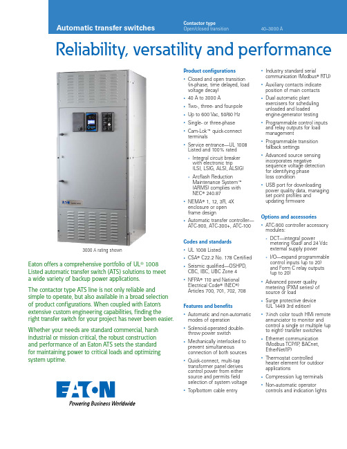
Reliability, versatility and performanceEaton offers a comprehensive portfolio of UL T 1008 Listed automatic transfer switch (ATS) solutions to meet a wide variety of backup power applications.The contactor type ATS line is not only reliable and simple to operate, but also available in a broad selection of product configurations. When coupled with Eaton’s extensive custom engineering capabilities, finding the right transfer switch for your project has never been easier. Whether your needs are standard commercial, harsh industrial or mission critical, the robust construction and performance of an Eaton ATS sets the standardfor maintaining power to critical loads and optimizing system uptime.Product configurations• Closed and open transition(in-phase, time delayed, loadvoltage decay)• 40 A to 3000 A• Two-, three- and four-pole• Up to 600 Vac, 50/60 Hz• Single- or three-phase• Cam-Lok E quick-connectterminals• Service entrance—UL 1008Listed and 100% rated• Integral circuit breakerwith electronic trip(LSI, LSIG, ALSI, ALSIG)• Arcflash ReductionMaintenance System E(ARMS) complies withNEC T 240.87• NEMA T 1, 12, 3R, 4Xenclosure or openframe design• Automatic transfer controller—ATC-900, ATC-300+, ATC-100Codes and standards• UL 1008 Listed• CSA T C22.2 No. 178 Certified• Seismic qualified—OSHPD,CBC, IBC, UBC Zone 4• NFPA T 110 and NationalElectrical Code T (NEC T)Articles 700, 701, 702, 708Features and benefits• Automatic and non-automaticmodes of operation• Solenoid-operated double-throw power switch• Mechanically interlocked toprevent simultaneousconnection of both sources• Quick-connect, multi-taptransformer panel derivescontrol power from eithersource and permits fieldselection of system voltage• Top/bottom cable entry• Industry standard serialcommunication (Modbus T RTU)• Auxiliary contacts indicateposition of main contacts• Dual automatic plantexercisers for schedulingunloaded and loadedengine-generator testing• Programmable control inputsand relay outputs for loadmanagement• Programmable transitionfallback settings• Advanced source sensingincorporates negativesequence voltage detectionfor identifying phaseloss condition• USB port for downloadingpower quality data, managingset point profiles andupdating firmwareOptions and accessories• ATC-900 controller accessorymodules:• DCT—integral powermetering (load) and 24 Vdcexternal supply power• I/O—expand programmablecontrol inputs (up to 20)and Form C relay outputs(up to 20)• Advanced power qualitymetering (PXM series) ofsource or load• Surge protective device(UL 1449 3rd edition)• 7-inch color touch HMi remoteannunciator to monitor andcontrol a single or multiple (upto eight) transfer switches• Ethernet communication(Modbus TCP/IP, BACnet,EtherNet/IP)• Thermostat controlledheater element for outdoorapplications• Compression lug terminals• Non-automatic operatorcontrols and indication lights3000 A rating shownProduct selection—catalog numbering systemA Limited to 400 A and below.B Emergency side circuit breaker available upon request. Check with factory.C Stainless steel option available for 1600–3000 A. Check with factory.D 304 or 316 grade stainless steel available for ratings up to 1200 A.Standard and optional ATC controller featuresAutomatic controllerA Modbus TCP/IP option requires use of Modbus RTU port.Quick-connect Cam-Lok terminationTransfer switches can be configured with a Cam-Lok power panel for quick connection to a temporary emergency power source (engine-generator).The color-coded power panel resides in an isolated compartment and is constructed of industry-standard 16 series Cam-Lokreceptacles (male) mounted on a high- strength fiberglass-reinforced polyester material. Each Cam-Lok receptacle is rated for 400 A and can be equipped with an optional hinged cover. Ground ampacity can be specified as 25%, 50% or 100% of the transfer switch ampere rating.Cam-Lok quick-connect panel (1200 A) with 25% (minimum) ground ampacity Door safety interlock Hinged door flapHinged bottom flap secures in closed position when cables are not presentDoor latches2EATON Automatic transfer switchesOpen transition—standard dimensions and weights1Transferswitch rating Device Dimensions in inches (mm)Normal,emergency, NeutralWeight Closed transition—standard dimensions and weights1Transferswitch rating Device Dimensions in inches (mm)Normal, emergency,NeutralWeight A Dimensions and weights are applicable fora standard product configuration at 480 V and subject to change. Please reference product outline drawings for the latest detailed information.B Neutral connection size listed is for productconfiguration with a solid neutral. For product configurations with a switched neutral (four-pole), reference the size listed in the Emergency/Load Connection column.C Three-pole product configuration.D Four-pole product configuration.3EATON Automatic transfer switchesEaton is a registered trademark.All other trademarks are property of their respective owners.Eaton1000 Eaton Boulevard Cleveland, OH 44122United States © 2021 EatonAll Rights Reserved Printed in USAPublication No. PA140015EN / Z24706January 2021UL 1008 withstand closing current ratingsTransferswitch rating Device Short-circuit withstand closing current rating (kA)Short-timewithstand closing current rating (kA)When protected by a circuit breaker When protected bya specific circuit breaker When protected by a specific fuseWhen protected by a circuit breaker Time duration(0.05 sec max.) AB Manufacturer and type based Manufacturer and type based Time duration (0.5 sec max.)480 Vac max. 600 Vac max. 480 Vac max. 600 Vac max. 480 Vac max. Fuse Max. fuse size 600 Vac max. Fuse Max. fuse size 480 Vac max. 600 Vacmax. A For open transition transfer switches rated 40–200 A (C2 device type), time duration is 0.025 sec maximum.B For closed transition transfer switches rated 40–200 A (C3 device type), time duration is 0.025 sec maximum.C For closed transition transfer switches rated 40–100 A (C3 device type) or 150–200 A (C3 device type), theshort-circuit withstand closing current ratings associated with a C2 device type apply.D Time duration is 0.13 sec maximum.E G5 device type only.Custom orderingIn many cases, standard products can be custom-order engineered to meet your application needs. For additional information, please contact your local Eaton sales representative.Follow us on social media to get thelatest product and support information.。
Schneider Electric 产品数据手册:ABLM1A12021调压电源说明书

T h e i n f o r m a t i o n p r o v i d e d i n t h i s d o c u m e n t a t i o n c o n t a i n s g e n e r a l d e s c r i p t i o n s a n d /o r t e c h n i c a l c h a r a c t e r i s t i c s o f t h e p e r f o r m a n c e o f t h e p r o d u c t s c o n t a i n e d h e r e i n .T h i s d o c u m e n t a t i o n i s n o t i n t e n d e d a s a s u b s t i t u t e f o r a n d i s n o t t o b e u s e d f o r d e t e r m i n i n g s u i t a b i l i t y o r r e l i a b i l i t y o f t h e s e p r o d u c t s f o r s p e c i f i c u s e r a p p l i c a t i o n s .I t i s t h e d u t y o f a n y s u c h u s e r o r i n t e g r a t o r t o p e r f o r m t h e a p p r o p r i a t e a n d c o m p l e t e r i s k a n a l y s i s , e v a l u a t i o n a n d t e s t i n g o f t h e p r o d u c t s w i t h r e s p e c t t o t h e r e l e v a n t s p e c i f i c a p p l i c a t i o n o r u s e t h e r e o f .N e i t h e r S c h n e i d e r E l e c t r i c I n d u s t r i e s S A S n o r a n y o f i t s a f f i l i a t e s o r s u b s i d i a r i e s s h a l l b e r e s p o n s i b l e o r l i a b l e f o r m i s u s e o f t h e i n f o r m a t i o n c o n t a i n e d h e r e i n .Product data sheetCharacteristicsABLM1A12021Regulated Power Supply, 100-240 V AC, 12 V2.1 A, single phase, ModularMainRange of product Modicon Power Supply Product or component typePower supplyPower supply type Regulated switch mode Variant option ModularNominal input voltage 100...240 V AC single phase 100...240 V AC 2 phases Input voltage limits 90...264 V AC Kw Rating 25 W Output voltage 12 V DC Power supply output current2.1 AComplementaryNominal network frequency 50…60 Hz Network system compatibilityTN TT ITMaximum leakage current 0.25 mA 240 V ACInput protection typeIntegrated fuse (not interchangeable) 3.15 A External protection (recommended) 20 A B External protection (recommended) 20 A C External protection (recommended) 4 A B External protection (recommended) 4 A C Inrush current25 A 115 V 50 A 230 V [Ue] rated operational voltage 115 V AC 0.48230 V AC 0.38Efficiency85 % 115 V AC 85 % 230 V AC Output voltage adjustment 12...15 V Power dissipation in W 4.6 WCurrent consumption < 0.8 A 115 V AC < 0.6 A 230 V AC Turn-on time < 2 sHolding time> 20 ms 115 V AC > 60 ms 230 V AC Startup with capacitive loads 3000 µF Residual ripple< 100 mV Expected capacitor life time 10 year(s)Meantime between failure [MTBF]5000000 H at 77 °F (25 °C), full load 1000000 h at 131 °F (55 °C), 80 % loadOutput protection typeAgainst overload and short-circuits automatic reset Against over temperature manual reset Against overvoltage manual resetConnections - terminals Screw connection 0.5...1.5 mm², AWG 20...AWG 16) without wire end ferrule Screw connection 0.5...1 mm², AWG 20...AWG 18) with wire end ferrule Line and load regulation < 0.5 %line < 1 %loadStatus LED Output voltage 1 LED Green)Depth2.19 in (55.6 mm)Maximum Height3.58 in (91 mm)Width1.42 in (36 mm)Net weight0.37 lb(US) (0.170 kg)Output coupling SerialMounting support Top hat type TH35-15 rail IEC 60715Top hat type TH35-7.5 rail IEC 60715Double-profile DIN railPanel mountingEnvironmentStandards EN 62368-1EN/IEC 61010-1EN 61010-2-201EN/IEC 61204-3EN 61000-6-1EN 61000-6-2EN 61000-6-3EN 61000-6-4EN 61000-3-2EN 61000-3-3EN 61000-4-3UL 1310UL 62368-1UL 61010-2-201UL 61010-1-201CSA C22.2 No 62368-1CSA C22.2 No 61010-2-201CSA C22.2 No 61010-1-201Product certifications CECUL ListedCUL RecognizedRCMCB SchemeOperating altitude< 6561.68 ft (2000 m) overvoltage category III2000 m...5000 m overvoltage category IIShock resistance100 m/s² 11 msIP degree of protection IP20Ambient air temperature for operation-13…131 °F (-25…55 °C) without current derating)131…158 °F (55…70 °C) with current derating of 2.67 % per °C)Ambient air temperature for storage-40…185 °F (-40…85 °C)Relative humidity0…95 % without condensationElectrical shock protection class Class II without PE connectionPollution degree2Vibration resistance 3 mm 2…9 Hz)IEC 60721-3-310 m/s² 9…200 Hz)IEC 60721-3-3Electromagnetic immunity Immunity to electrostatic discharge 6 kV contact discharge) EN/IEC 61000-4-2Immunity to electrostatic discharge 9 kV air discharge) EN/IEC 61000-4-2Electromagnetic field immunity test 10 V/m 80 MHz...2 GHz) EN/IEC 61000-4-3Electromagnetic field immunity test 5 V/m 2...2.7 GHz) EN/IEC 61000-4-3Electromagnetic field immunity test 3 V/m 2.7...6 GHz) EN/IEC 61000-4-3Immunity to fast transients 4 kV on input-output) EN/IEC 61000-4-4Surge immunity test 3 kV between power supply and earth) EN/IEC 61000-4-5Surge immunity test 1.5 kV between phases) EN/IEC 61000-4-5Immunity to conducted disturbances 10 Vrms 0.15...80 MHz) EN/IEC 61000-4-6Immunity to magnetic fields 30 A/m 50...60 Hz) EN/IEC 61000-4-8Immunity to voltage dips 100 % 1 cycle) EN/IEC 61000-4-11Immunity to voltage dips 60 % 10 cycles) EN/IEC 61000-4-11Immunity to voltage dips 30 % 25 cycles) EN/IEC 61000-4-11Disturbing field emission IEC 55016-2-3Limits for harmonic current emissions IEC 61000-3-3Micro-cuts and voltage fluctuation IEC 55016-1-2Micro-cuts and voltage fluctuation IEC 55016-2-1Electromagnetic emission Conducted emissions EN 61000-6-3Radiated emissions EN 61000-6-4Dielectric strength3000 V AC input/outputOffer SustainabilityREACh free of SVHC YesEU RoHS Directive Pro-active compliance (Product out of EU RoHS legal scope)EU RoHSDeclarationMercury free YesRoHS exemption information YesChina RoHS Regulation China RoHS DeclarationWEEE The product must be disposed on European Union markets following specificwaste collection and never end up in rubbish bins.Dimensions DrawingsElectrical Safety●If the unit is use in a manner not specified by the manufacturer, the protection provided by the equipment may be impaired.●For means of disconnection a switch or circuit breaker, located near the product, must be included in the installation. A marking asdisconnecting device for the product is required.●The device has an internal fuse. The unit is tested and approved with branch circuit protective device up to 20A. This circuit breaker canbe used as disconnecting device.DimensionsSide and Rear ViewConnections and SchemaRegulated Switch Mode Power Supplies Correct Parallel Connection(1) :LoadIncorrect Parallel Connection(1) :LoadABLx1Axxxxx-1 = ABLx1Axxxxx-2max 2 x ABLx1AxxxxxL1 = L2∆V max 25 mVL Load < 90% 2 x L nomSeries Connection(1) :V out1(2) :V out2(3) : 2 x Diode, V RPM> 2 x V out1/2, L F > 2 x L nom1/2(4) :V Load = 2 x V out(5) :LoadOutput Voltage Balancing(1) :R Load1(2) :R Load2R Load1= R Load2L1= L 2= ~ L nomPerformance Curves Performance CurveX :Ambient Temperature (ºC) Y :Percentage of Max Load (%)1 :Mounting A2 :Mounting BMounting and Clearance Mounting(1) :Mounting A(2) :Mounting BIncorrect Mounting。