绝对值SSI编码器
SSI编码器

DOS58 单圈绝对值SSI系列
单圈SSI同步串行信号输出 型号:DOS58011K1R4096-SC (常规型)
港口起重运输机械及造纸印刷、水利闸门、大型重型机械设备、机床、包装机械
外形尺寸:(夹紧法兰 单位 mm 盲孔轴套、同步法兰可选)
DOS系列电缆线侧出L=40 可选后出线
* 绝对值码盘,高精度全数字化,无需电池,无信号干扰、零点飘移之虞。
* SSI数字输出,最快可设时钟频率500KHz,高速度、高精度控制, 宽工作电压,极低的耗电流。
* 夹紧法兰、同步法兰或盲孔轴套,国际标准外形结构,与德国各品牌编码器可互换。
特性参数
工作电压:10…30Vdc极性保护
消耗电流:40mA(24Vdc);80mA(12Vdc)
输出信号:SSI同步串行信号,格雷码输出
线性分辨度:标准12位4096分辨率,可选13位8192、16位65536分辨率
重复精度:重复性±2BIT(实际精度与安装精度、轴同心度有关)
时钟速率:最快可设时钟频率500KHz,推荐使用125KHz
工作温度:-25~80℃
储存温度:-40~85℃
防护等级:IP65 IP67可选
振动冲击:10g,10~2000Hz;100g,6ms
允许转速:2400转/分
连接电缆:1米屏蔽电缆径向侧出 (其余形式可订货)
SSI信号特性:。
基于SPI读取绝对值编码器SSI信号的方法设计概述
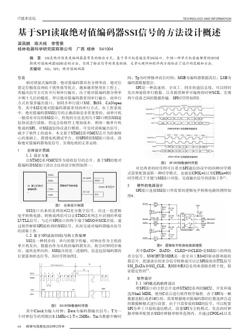
图5 绝对值编码器SSI输出波形图 图6 系统SPI接收的仿真波形图
本文从硬件和软件两方面设计阐述了基于SPI的绝对值编接口的信号读出方法,相比于IO口模拟SSI协议的方法的资源,基于此读出方法的伺服驱动系统也实现了与永磁同步电机的匹配调试。
参考文献
[1] STM32F10XXX User’s manual[M]. STMicroelectronics,2009:1-548.
[2] 陈志同.基于SSI协议的绝对值编码器通信接口研究
津理工大学,2014.
传统的仿真环境工作在行为级,仿真环境高度耦合,一旦
设计趋于复杂,整个仿真环境架构会非常混乱,不易维护。
基
软仿真架构给出了多层次的事务级仿真平台解
区。
而对于那些受约束的随机测试覆盖不到的地方,再补充定。
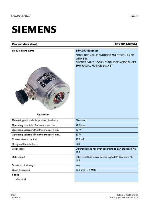
SIMODRIVE 6FX2001-5FS24 绝对值编码器多转动25位SSI操作电压10-30V
Product data sheet
product brand name
Page 1
6FX2001-5FS24
SIMODRIVE sensor ABSOLUTE VALUE ENCODER MULTITURN 25 BIT WITH SSI, OPERAT. VOLT. 10-30 V SYNCHROFLANGE SHAFT 6MM RADIAL FLANGE SOCKET
Yes Set to zero Yes 79 " (with 8192 increments) 0.01 N·m 0.01 N·m
10 N 20 N
40 N 60 N 6 mm 10 mm 100000 rad/s²
Page 2
subject to modifications © Copyright Siemens AG 2013
subject to modifications © Copyright Siemens AG 2013
6FX2001-5FS24
• with ± 1 bit accuracy / max. • with ± 100 bit accuracy / max. • mechanical / max. Length of cable to subsequent electronics • up to 1 MHz, max. • up to 100 kHz, max. • up to 300 kHz, max. • max. Digital resolution • note Telegram • note Code type • Sampling • Transfer Parameterization capability • Preset • Preset • Counting direction Accuracy • note Friction torque at 20°C / max. Starting torque at 20 °C / max. Shaft load capacity • at n > 6000 rpms • axially, max. • radially on shaft end, max. • at n ≤ 6000 rpms • axially, max. • radially on shaft end, max. External diameter / of rotary encoder shaft Length / of rotary encoder shaft Angular acceleration / maximum Moment of inertia of rotor
绝对值编码器

绝对值编码器简介(Absolute Encoder)绝对值编码器简介(Absolute Encoder)是相对于增量而言的,顾名思义,所谓绝对就是编码器的输出信号在一周或多周运转的过程中,其每一位置和角度所对应的输出编码值都是唯一对应的,如此,便具备掉电记忆绝对之功能也。
绝对式编码器是依据计算机原理中的位码来设计的,比如:8位码(0000 0011),16位码,32位码等。
把这些位码信息反映在编码器的码盘上,就是多道光通道刻线,每道刻线依次以2线、4线、8线、16线。
编排。
如此编排的结果,比如对一个单圈绝对式而言,便是把一周360°分为2的4次方,2的8次方,2的16次方,,,,位数越高,则精度越高,量程亦越大。
这样,在编码器的每一个位置,通过读取每道刻线的通、暗,获得一组从2的零次方到2的n-1次方的唯一的2进制编码(格雷码),这就称为n位绝对编码器。
这样的编码器是由光电码盘的机械位置决定的,它不受停电、干扰的影响。
绝对编码器由机械位置决定的每个位置是唯一的,它无需记忆,无需找参考点,而且不用一直计数,什么时候需要知道位置,什么时候就去读取它的位置。
这样,编码器的抗干扰特性、数据的可靠性大大提高了。
单圈绝对值编码器到多圈绝对值编码器旋转单圈绝对值编码器,以转动中测量光电码盘各道刻线,以获取唯一的编码,当转动超过360度时,编码又回到原点,这样就不符合绝对编码唯一的原则,这样的编码只能用于旋转范围360度以内的测量,称之为单圈绝对值编码器。
如果要测量旋转超过360度范围,就要用到多圈绝对值编码器。
编码器生产厂家运用钟表齿轮机械的原理,当中心码盘旋转时,通过齿轮传动另一组码盘(或多组齿轮,多组码盘),在单圈编码的基础上再增加圈数的编码,以扩大编码器的测量范围,这样的绝对编码器就称为多圈式绝对编码器,它同样是由机械位置确定编码,每个位置编码唯一不重复,而无需记忆。
多圈编码器另一个优点是由于测量范围大,实际使用往往富裕较多,这样在安装时不必要费劲找零点,将某一中间位置作为起始点就可以了,而大大简化了安装调试难度。
基于SPI读取绝对值编码器SSI信号的方法设计概述

基于SPI读取绝对值编码器SSI信号的方法设计概述作者:梁昌鹏陈天桂李雪景来源:《科学与信息化》2020年第05期摘要 SSI是绝对值角度编码器最常见的输出方式,基于单片机普遍没有SSI接口,介绍一种单片机普遍都有的SPI读取绝对值编码器SSI输出的方法,实现了输出信号的角度转换。
文章从硬件和软件两方面给出了设计的思路和方法。
关键词 SSI;SPI;绝对值编码器引言相对增量式编码器,绝对值编码器具有分辨率高、绝对位置定位精度高和抗干扰性强等优点,越来越多使用在工控上,其输出信号方式有并行和串行输出,由于绝对值编码器分辨率少则十几位的精度,所以绝对值编码器常用串行输出。
而串行方式有很多输出接口,如同步串行接口SSI、BiSS、CANopen等,其中SSI是绝对值编码器最常用的串行方式。
在工控系统中,绝对值编码器SSI信号的正确读取是非常重要的,而单片机一般没有对应的SSI接口,传统的方法是用几个IO口模拟SSI通信协议进行读取,但这会给软件上增加成本。
利用一般单片机集成的SPI,对SSI通信协议进行模拟,可实时读取输出信号,减少了软件上的成本。
本文基于STM32系列MCU芯片为控制核心的基础上,搭建电机测试平台,用SPI模拟SSI接口协议,读取绝对值编码器角度信号,实现电机的正常运转。
1 总体设计思路1.1 设计方案以STM32系列MCU作为接收信号的芯片,基于SPI的绝对值编码器SSI接口读出方法的设计框图如图一。
SSI接口出来的是两组422差分数字信号,经过一组逻辑电平转换电路,转换成两组可以让STM32系列芯片识别的单端LVTLL信号,与芯片SPI接口的两个端子MISO和SCK对接,通过软件解析SPI接收到的SSI信号,从而完成对编码器输出信号的读取工作。
1.2 基于SPI读出SSI信号的工作原理SSI是一种同步的、串行的数字传输,时钟由作为主机的单片机发出,数据由作为从机的编码器发出,配合时钟同步响应,通讯是单向的。
SSI编码器

SSI编码器简介应用行业:
一.BEN绝对值编码器的常规外形:38MM,58MM,66MM,80MM.100MM. 二.BEN绝对值编码器分为:单圈,多圈。
三.BEN绝对值编码器按原理分为:磁绝对值编码器,光电绝对值编码器
四.BEN绝对值编码器出线方式分为:侧出线,后出线
五.BEN绝对值编码器轴分为:6MM,8MM,10MM,12MM,14MM,25MM. 六.BEN绝对值编码器分为:轴,盲孔,通孔。
七.BEN绝对值编码器防护分为:IP54-68.
八.BEN绝对值编码器安装方式分为:夹紧法兰、同步法兰、夹紧带同步法兰、盲孔(弹簧片,抱紧)、通孔(弹簧片,键销)九.BEN绝对值编码器精度分为:单圈精度和多圈精度,加起来是总精度,也就是通常的多少位(常规24位,25位,30位,32位。
)。
十.BEN绝对值编码器通讯协议波特率:4800~115200 bit/s,默认为9600 bit/s。
刷新周期约1.5ms ★精芬机电传感器
*机床
*航天航空、
*造纸印刷、
*水利闸门、
* 纺织机械
* 灌溉机械
* 军工设备
* 食品机械
*钢铁冶金设备
* 机器人及机械手臂*港口起重运输机械*大型重型机械设备*精密测量和数控设备
技术参数
BEN编码器外形尺寸。
SSI接口的绝对值角度编码器值的读出方法研究
reg【23:O】sbuLreg.sbuLreg 1:
reg【1:O】cIk-c:
reg【3:O】l-read: reg【7:O】tm.-c:
//cIock高持续时间计数
reg mcIkj://clOck去抖后的真值
reg【4:0】rkc:
//clock去抖计时
reg sLreg:
reg rx—slart,rx—stan_-o:
参考文献 1 夏宇闻.VeriIog数字系统设计教程【M].北京:北京航空航天大学出版
社。2004 2 AItera COrpOralion.AItera DlgitaI L的ra广y,March 2002 3 AItera Corporation.MA×7000 ProgrammabIe Logic DeVice Da—
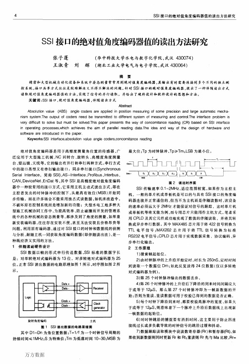
SSI数据以帧的形式串行传送数据,SSI标准的数据字长 是:对单转绝对式编码器为13位,对多转绝对式编码器为25 位。正常SSI读出数据的电路原理如图1所示,时序图如图2所 示。
旋转角度编码
主机
图1 SSI读出数据的电路原理图
其中D1~Dn为角位置数据;T=1/f为一个时钟信号周期的
持续时间≤1MHz;S为特殊位;Tm为低落时间10—30;MSB为
RS232电平信号;CPLD芯片用于实现数据采集、协议编码、异
步串行化输出。 2工作原理
1)搜索帧起始位。
2)由时钟脉冲的上升沿开始定时,时长为250nS,定时时间
到读取一个数据位Dm;如此反复读得24位数据(仅以多转绝
对式编码器为例)。
3)第25个时钟脉冲输出的数据丢弃。
4)第26个时钟脉冲的上升沿后下降沿的到来时间间隔应大
最大位;Tp为时钟脉冲,Tp≥Tm;LSB为最小位。
ArmorPoint I O 同步串行接口(SSI)绝对编码器模块,系列A(Cat. No. 173
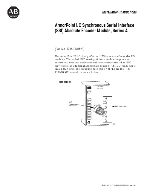
Installation Instructions ArmorPoint I/O Synchronous Serial Interface (SSI) Absolute Encoder Module, Series A(Cat. No. 1738-SSIM23)The ArmorPoint™ I/O family (Cat. no. 1738) consists of modular I/O modules. The sealed IP67 housing of these modules requires no enclosure. (Note that environmental requirements other than IP67 may require an additional appropriate housing.) The I/O connector is sealed M23 style. The mounting base ships with the module. The 1738-SSIM23 module is shown below.1738-SSIM23M23ConnectorPublication 1738-IN013A-EN-E - June 20042 ArmorPoint I/O Synchronous Serial Interface (SSI) Absolute Encoder Module, Series AImportant User InformationSolid state equipment has operational characteristics differing from those of electromechanical equipment. Safety Guidelines for the Application, Installation and Maintenance of Solid State Controls (Publication SGI-1.1 available from your local Rockwell Automation sales office or online at/manuals/gi) describes some important differences between solid state equipment and hard-wired electromechanical devices. Because of this difference, and also because of the wide variety of uses for solid state equipment, all persons responsible for applying this equipment must satisfy themselves that each intended application of this equipment is acceptable.In no event will Rockwell Automation, Inc. be responsible or liable for indirect or consequential damages resulting from the use or application of this equipment.The examples and diagrams in this manual are included solely for illustrative purposes. Because of the many variables and requirements associated with any particular installation, Rockwell Automation, Inc. cannot assume responsibility or liability for actual use based on the examples and diagrams.No patent liability is assumed by Rockwell Automation, Inc. with respect to use of information, circuits, equipment, or software described in this manual.Reproduction of the contents of this manual, in whole or in part, without written permission of Rockwell Automation, Inc. is prohibited.Throughout this manual we use notes to make you aware of safety considerations..Publication 1738-IN013A-EN-E - June 2004ArmorPoint I/O Synchronous Serial Interface (SSI) Absolute Encoder Module, Series A 3Environment and EnclosureThis equipment is intended for use in overvoltageCategory II applications (as defined in IECpublication 60664-1), at altitudes up to 2000 meterswithout derating.This equipment is considered Group 1, Class Aindustrial equipment according to IEC/CISPRPublication 11. Without appropriate precautions,there may be potential difficulties ensuringelectromagnetic compatibility in other environmentsdue to conducted as well as radiated disturbance.This equipment is supplied as "enclosed" equipment.It should not require additional system enclosurewhen used in locations consistent with the enclosuretype ratings stated in the Specifications section of thispublication. Subsequent sections of this publicationmay contain additional information regardingspecific enclosure type ratings, beyond what thisproduct provides, that are required to comply withcertain product safety certifications.NOTE: See NEMA Standards publication 250 andIEC publication 60529, as applicable, forexplanations of the degrees of protection providedby different types of enclosure. Also, see theappropriate sections in this publication, as well asthe Allen-Bradley publication 1770-4.1 ("IndustrialAutomation Wiring and Grounding Guidelines"), foradditional installation requirements pertaining to thisequipment.Publication 1738-IN013A-EN-E - June 2004Publication 1738-IN013A-EN-E - June 20044 ArmorPoint I/O Synchronous Serial Interface (SSI) Absolute Encoder Module, Series AMount the I/O Base To mount the ArmorPoint I/O base on a wall or panel, use the screwholes provided in the ArmorPoint base.A mounting illustration for the ArmorPoint base with an adapter is shown below.Preventing Electrostatic DischargeThis equipment is sensitive to electrostatic discharge,which can cause internal damage and affect normaloperation. Follow these guidelines when you handlethis equipment:•Touch a grounded object to discharge potentialstatic.•Wear an approved grounding wriststrap.•Do not touch connectors or pins on componentboards.•Do not touch circuit components inside theequipment.•If available, use a static-safe workstation.•When not in use, store the equipment in appropriate static-safe packaging.The ArmorPoint I/O module must be mounted on agrounded metal mounting plate or other conductive surface.ArmorPoint I/O Synchronous Serial Interface (SSI) Absolute Encoder Module, Series A 5Install the mounting base as follows:y out the required points as shown above in the drillingdimension drawing.2.Drill the necessary holes for #8 (M4) machine or self-tappingscrews.3.Mount the base using #8 (M4) screws.4.Ground the system using the ground lug connection. (Theground lug connection is also a mounting hole.)Mounting basemodulesPublication 1738-IN013A-EN-E - June 20046 ArmorPoint I/O Synchronous Serial Interface (SSI) Absolute Encoder Module, Series AInstall the ArmorPoint SSI Absolute Encoder Module To install the ArmorPoint SSI Absolute Encoder module, proceed as follows.ing a bladed screwdriver, rotate the keyswitch on themounting base clockwise until the number 2 aligns with thenotch in the base.2.Position the module vertically above the mounting base. Themodule will bridge two bases.3.Push the module down until it engages the latching mechanism.You will hear a clicking sound when the module is properlyengaged.The locking mechanism will lock the module to the base. Remove the ArmorPoint SSI Absolute Encoder Module From the Mounting BaseTo remove the module from the mounting base:1.Put a flat blade screwdriver into the slot of the orange latchingmechanism.2.Push the screwdriver toward the I/O module to disengage thelatch.The module will lift up off the base.3.Pull the module off of the base.Publication 1738-IN013A-EN-E - June 2004ArmorPoint I/O Synchronous Serial Interface (SSI) Absolute Encoder Module, Series A 7Wire the SSI Absolute Encoder Module Following are wiring instructions for the ArmorPoint SSI Absolute Encoder module.1738-SSIM23Shield lead can be connected to chassis pin 5 or 12on the connector.Make sure all connectors and caps are securelytightened to properly seal the connections againstleaks and maintain IP67 requirements.Pin 7 -Clock +Pin 8 -Clock -Pin 9 -Return (Com)Pin 10 -Return (Com)Pin 11 -24 V dcPin 12 -ChassisPublication 1738-IN013A-EN-E - June 20048 ArmorPoint I/O Synchronous Serial Interface (SSI) Absolute Encoder Module, Series ACommunicate With Your Module The 1738-SSIM23 module transmits SSI sensor data over the DeviceNet™, ControlNet™, Ethernet®, and PROFIBUS network. Data can be exchanged with the master through a polled, cyclic, or change-of-state connection. The module produces 10 byes of data and consumes 2 bytes of data.Default Data Map for the ArmorPoint Absolute Encoder Module 1738-SSIM23Message Size: 10 BytesConsume and Produce Bit/Byte DefinitionsByte Bit DescriptionProduce 00-7Low byte of present low SSI word. Bit 0 is the leastsignificant bit of the entire present SSI word.Produce 10-7High byte of present low SSI word.Produce 20-7Low byte of present high SSI word.Produce 30-7High byte of present high SSI word. Bit 7 is the mostsignificant bit of the entire present SSI word.Produce 40-7Low byte of stored low SSI word. Bit 0 is the leastsignificant bit of the entire stored SSI word.Produce 50-7High byte of stored low SSI word.Produce 60-7Low byte of stored high SSI word.Produce 70-7High byte of stored high SSI word. Bit 7 is the mostsignificant bit of the entire stored SSI word.Byte Bit Description Produce 876543210Status Byte 0 C2ST C1ST C2R C1R INC DEC RUN I1Produce 976543210Status Byte 1 RES RES RES LHON IDF1CCE CCF SPF1Monitor IDF to determine the validity of the produced data. If IDF=1, the SSI data is false.Publication 1738-IN013A-EN-E - June 2004ArmorPoint I/O Synchronous Serial Interface (SSI) Absolute Encoder Module, Series A 9 Message Size: 2 BytesTroubleshoot with the IndicatorsByte Bit Description Consume 076543210Master ACK Byte1 RES RES RES SCMP2SCMP1CC2CC1LACKConsume 176543210CONS1RES RES RES RES RES RES RES RES1The master must provide the Master ACK Byte in order to receive the polled Produced bytes 0-9.Indication Probable CauseModule StatusOff No power applied to deviceGreen Device operating normallyFlashing Green Device needs commissioning due to missing, incomplete, orincorrect configurationFlashing Red Recoverable faultRed Unrecoverable fault - may require device replacement Flashing Red/Green Device is in self-test1738-SSIM23Publication 1738-IN013A-EN-E - June 200410 ArmorPoint I/O Synchronous Serial Interface (SSI) Absolute Encoder Module, Series AIndication Probable CauseNetwork StatusOff Device is not on line:- Device has not completed dup_MAC-id test.- Device not powered - check module status indicator.Flashing Green Device is on line but has no connections in the established state.Green Device is on line and has connections in the established state.Flashing Red One or more I/O connections in timed-out state.Red Critical link failure - failed communication device. Devicedetected error that prevents it from communicating on thenetwork.Flashing Red/Green Communication faulted device - the device has detected anetwork access error and is in communication faulted state.Device has received and accepted an Identity CommunicationFaulted Request - long protocol message.Indication Probable CauseI/O StatusRun StatusOff Module is commanded to stop retrieving SSI data.Green Module is commanded to retrieve SSI data.Up StatusOff SSI data not increasing or no SSI data is being received.Green SSI data is increasing.Down StatusOff SSI data not decreasing or no SSI data is being received.Green SSI data is decreasing.Comp StatusOff Comparator function not in use or comparator value not attained.Green Comparator value is attained.I1 StatusOff Latching input I1 is OFF.Green Latching input I1 is ON.Publication 1738-IN013A-EN-E - June 2004ArmorPoint I/O Synchronous Serial Interface (SSI) Absolute Encoder Module, Series A 11 Specifications Following are specifications for the 1738 ArmorPoint SSI AbsoluteEncoder module.ArmorPoint 1738-SSIM23 ModuleNumber of SSI Channels1Encoder Type Any absolute encoder supporting standard SSI protocol including linear, rotary, andoptical distance measuring devices.Most-Significant Bit Aligned data format. Physical interface for clock and data signals isRS-422.SSI Data Rate125kHz, 250kHz, 500kHz, 1MHz, 2MHz (software selectable)SSI Bits Per Word2-31 (software selectable)SSI Word Delay Time116µs-64ms (software selectable)SSI Word Length 4 bytes (32 bits)SSI Features Gray or binary code capable with gray to binary conversion, increasing or decreasing SSIcount indication, 2 SSI word comparator values, SSI word latching with I1 input.SSI Position Forming Time2> 0.5msSSI Cable Type UL CM/AWM 2464/CSA Type CMG FT4 or similar cable utilizing shielded twisted pairsfor D+/- and C+/- connections. See sensor manufacturer for actual cable required for theSSI sensor under use. I1 input can be wired separate from SSI cable1.SSI Cable Length Depends on desired SSI data rate:125kHz - 1050ft (320m)250kHz - 525ft (160m)500kHz - 195ft (60m)1MHz - 65ft (20m)2MHz - 25ft (8m)SSI Sensor Power (At V +/- Terminals)10-28.8V dc common with field power voltage, 0.75A dc maximum with short circuit protectionSSI Clock Drive Current(Out of Clock +/- Terminals)125mA maximumInput I1IEC Type 3 voltage and current characteristics, sourcing typeMinimum Nominal MaximumON-State Voltage0V dc--FPV* -10ON-State Current2mA4mA5mA(FPV=24V dc)OFF-State Voltage FPV-5--FPVOFF-State Current 1.2mA----Input Impedance-- 3.6kΩ 4.7kΩInput Filter Time--0.5ms--* = FPV Field Power Supply VoltageField Power Supply Voltage (Bus Supply)Minimum Nominal Maximum10V dc24V dc28.8V dcKeyswitch Position2Publication 1738-IN013A-EN-E - June 200412 ArmorPoint I/O Synchronous Serial Interface (SSI) Absolute Encoder Module, Series AGeneral SpecificationsLED Indicators 1 green run status, logic side1 green up status, logic side1 green down status, logic side1 green comp status, logic side1 green/red network status, logic side1 green/red module status, logic side PointBus Current, Maximum110mAPower Dissipation, Maximum0.94 W @ rated loadThermal Dissipation, Maximum 3.21 BTU/hr. @ rated loadIsolation Voltage(continuous-voltage withstand rating)50V rmsTested at 1250V ac rms for 60sDimensions Inches (Millimeters) 1.25H x 2.63W x 4.25D (31.75H x 66.80W x 107.95D) Operating Temperature IEC 60068-2-1 (Test Ad, Operating Cold),IEC 60068-2-2 (Test Bd, Operating Dry Heat),IEC 60068-2-14 (Test Nb, Operating Thermal Shock):-20 to 60°C (-4 to 140°F)Storage Temperature IEC 60068-2-1 (Test Ab, Un-packaged Non-operating Cold),IEC 60068-2-2 (Test Bb, Un-packaged Non-operating Dry Heat),-40 to 85°C (-40 to 185°F)Relative Humidity IEC 60068-2-30 (Test Db, Un-packaged Non-operating Damp Heat):5-95% non-condensingShock IEC60068-2-27 (Test Ea, Unpackaged Shock):Operating 30gNon-operating 50gVibration IEC60068-2-6 (Test Fc, Operating):5g @ 10-500HzESD Immunity IEC 61000-4-2:6kV contact discharges8kV air dischargesRadiated RF Immunity IEC 61000-4-3:10V/m with 1kHz sine-wave 80%AM from 30MHz to 1000MHz EFT/B Immunity IEC 61000-4-4:±2kV at 5kHz on signal portsSurge Transient Immunity IEC 61000-4-5:±1kV line-line(DM) and ±2kV line-earth(CM) on signal ports±2kV line-earth(CM) on shielded portsConducted RF Immunity IEC 61000-4-6:10Vrms with 1kHz sine-wave 80%AM from 150kHz to 80MHz Emissions CSPR 11:Group 1, Class AEnclosure Type Rating Meets IP65/66/67 (when marked)Mounting Base Screw Torque#8 screw, 7.5 in. lbs. in Aluminum, 16 in. lbs. in SteelWeight Imperial (Metric)0.637 lb. (0.289 kg)Wiring Category3 2 - on signal portsPublication 1738-IN013A-EN-E - June 2004ArmorPoint I/O Synchronous Serial Interface (SSI) Absolute Encoder Module, Series A 13 General Specifications (continued)Certifications:(when product is marked)c-UL-us UL Listed Industrial Control Equipment, certified for US and CanadaCE4European Union 89/336/EEC EMC Directive, compliant with:EN 61000-6-4; Industrial EmissionsEN 50082-2; Industrial ImmunityEN 61326; Meas./Control/Lab., Industrial RequirementsEN 61000-6-2; Industrial ImmunityC-Tick4Australian Radiocommunications Act, compliant with: AS/NZS CISPR 11;Industrial Emissions1Time between successive SSI words (T p) (also called Dwell Time).2Roughly corresponds to the maximum time the SSI sensor can be expected to output a particular position value while in motion. To use the 1738-SSI module with sensors that have faster position forming times, change the SSI Word Filter Control parameter from its default value of 5 (max). Changing this parameter from its default value sacrifices electrical noise environment performance for sensor data conversion speed.3Use this conductor category information for planning conductor routing as described in publication 1770-4.1, “Industrial Automation Wiring and Grounding Guidelines.”4See the Product Certification link at for Declarations of Conformity, Certificates, and other certification details.Publication 1738-IN013A-EN-E - June 2004Rockwell Automation SupportRockwell Automation provides technical information on the web to assist you in using our products. At, you can find technical manuals, a knowledge base of FAQs, technical and application notes, sample code and links to software service packs, and a MySupport feature that you can customize to make the best use of these tools.For an additional level of technical phone support for installation, configuration and troubleshooting, we offer TechConnect Support programs. For more information, contact your local distributor or Rockwell Automation representative, or visit .Installation AssistanceIf you experience a problem with a hardware module within the first 24 hours of installation, please review the information that's contained in this manual. You can also contact a special Customer Support number for initial help in getting your module up and running:United States 1.440.646.3223Monday – Friday, 8am – 5pm ESTOutside United States Please contact your local Rockwell Automation representative for any technical support issues.New Product Satisfaction ReturnRockwell tests all of our products to ensure that they are fully operational when shipped from the manufacturing facility. However, if your product is not functioning and needs to be returned:United States Contact your distributor. You must provide a Customer Support case number (see phone numberabove to obtain one) to your distributor in order to complete the return process.Outside United States Please contact your local Rockwell Automation representative for return procedure.ArmorPoint is a trademark of Rockwell Automation.DeviceNet is a trademark of Open DeviceNet Vendor Association.ControlNet is a trademark of ControlNet International, Ltd.Ethernet is a registered trademark of Digital Equipment Corporation, Intel, and Xerox Corporation.Publication 1738-IN013A-EN-E - June 2004 PN 957824-39Copyright © 2004 Rockwell Automation, Inc. All rights reserved. Printed in the U.S.A.。
- 1、下载文档前请自行甄别文档内容的完整性,平台不提供额外的编辑、内容补充、找答案等附加服务。
- 2、"仅部分预览"的文档,不可在线预览部分如存在完整性等问题,可反馈申请退款(可完整预览的文档不适用该条件!)。
- 3、如文档侵犯您的权益,请联系客服反馈,我们会尽快为您处理(人工客服工作时间:9:00-18:30)。
工业级SSI 信号 GEX58011K1R4096/4096-S (出轴型/盲孔型)
可靠的和专利的
●
具有安全锁(Sa fety-Lock TM )式设计的坚固轴承结构,可以提供更高的抗振动性和防安装误差性
● IP68防护等级和宽广的工作温度范围-40℃...+85℃ ● 专利化机械齿轮技术,具有永久断电记忆功能
性能优化
● 高精度,位置数据的数据刷新率≤4us ● 通过RS422实现高分辨率反馈 ● 控制周期短。
时钟频率最快可达1MHz ●
国际标准SSI 信号格式
机械参数 电气参数 最大转速 6000转/分
工作电压 10-30Vdc (5Vdc 可定制) 主轴负载 轴向40N ,径向100N 消耗电流 < 50mA (24Vdc)空载
抗冲击 1000m/s ²(6ms),等于100g 输出信号 25位SSI 同步串行信号(格雷码和纯二进制可选) 抗振动 200m/s ²(10-2000Hz),等于20g 线性分辨率 1/4096FS 和1/8192FS 允许轴向窜动 ±1.5mm 最大工作圈数 4096圈(256圈/64圈可选) 允许径向跳动 ±0.2mm
重复定位精度 小于2Bit 外形结构 60mm 外径,实心轴,盲孔轴 工作温度 -40℃~85℃ 连接形式
8芯屏蔽电缆或航空插头
储存温度
-40℃~85℃
SSI 协议说明:
SSI 为同步串联信号,实际的两对RS422,一对时钟触发,一对数据发送。
如右图所示,编码器的绝对位置值由接收设备的时钟信号触发,从格雷码高位(MSB)开始,输出与时钟信号同步的串行信号。
时钟信号从接收设备发出,以编码器的总位数输出N 个中断的脉冲,当不传送信号时,时钟和数据位均是高位,在时钟信号的第一个下降沿,当前值开始贮存,从时钟信号上升沿开始,数据信号开始传送,一个时钟脉冲同步一位数据。
其中:t3为恢复信号,等待下次传送;N=13;16;25;28。
根据编码器总位数。
T=4—11us ; t1=1—5.5us ; t2≤1us ; t3=11—15.5us (Clock-及Date-省略未画)。
实际使用中,为保证信号的稳定与较远的传输距离,推荐参数如下: T=8us (125KHz ); t1=4us ; t2′(实际读数延迟时间)=3~4us ; t3=15us 。
具有专利化机械齿轮计圈式多圈编码器,不含电池,
具有永久断电记忆功能。
100%抗磁场干扰性,欧标 安装尺寸,盲孔孔径可选8-15mm 孔。
工业级SSI信号GEX58011K1R4096/4096-S(出轴型/盲孔型)
接线图:
功能+V 0V CLOCK+CLOCK-DATA+ DATA-DIR MID P屏蔽
颜色棕色白色绿色黄色灰色粉色蓝色黑色网
a.DIR—旋转方向,低电平时,默认为面对转轴顺时针数据增加,加工作电源高电平时,方向改变为逆时针数据增加;
b.MID P—中点定位,当与高电平短触时,当前位置数据输出为整个数据的中点位置;正常工作时,与电源0V连接。
c.Clock/Data--四线的RS422模式,±5V,一对时钟触发、一对数据输出;
数据处理方法详见产品说明书.
尺寸图:
盲孔型 60mm外径 8-15mm孔径可选夹紧法兰 60mm外径 6/8/10mm轴径可选
20mm孔深轴向出线可选 20mm轴长轴向出线可选
夹紧同步法兰 60mm外径 6/8/10mm轴径可选同步(伺服)法兰 60mm外径 6mm轴径
20mm轴长轴向出线可选 10mm轴长轴向出线可选。