日本SHIMPO新宝 VRL系列减速机
NIDEC-SHIMPO 精密齿轮技术指南说明书

Precision Gear Technology GuideNidec-SHiMPO cORPORATiONOur companyNIDEC-SHIMPO has established itself as the leading supplier of precision gearing solutions to the industrial automation mar-ketplace. Since 1952, when we introduced the world’s first mechanical variable speed drive, NIDEC-SHIMPO has expanded into a diverse manufacturer of high precision power transmission systems for highly dynamic motion control applications. In 1994, SHIMPO was acquired by the NIDEC Corporation and became formally known as NIDEC-SHIMPO. NIDEC-SHIMPO began to focus on accelerating production volumes as the global market for motion control and mechatronics grew at an acceler-ated rate. We saw a unique opportunity to supply our customer base with the highest variety of transmission technologies, which brought forward strain wave, index table and worm gear products to complement our existing portfolio of planetary and cycloidal gearheads. The result for our customers was a single source drive solutions supplier.Today, our company is shipping over 100,000 gearheads per month out of our manufacturing plants in Kyoto and Shanghai. Our products are used in robotics, machine tools, food packaging, printing, paper converting, material handling, medical, semiconductor and aerospace related systems. Our diverse product portfolio, state-of-the-art equipment, engineering know-how and manufacturing scale allow our customers to compete and expand their businesses globally. NIDEC-SHIMPO has over 2,400 employees strong with a presence across five continents. Our engineering staff, customer support team and dis-tribution partners undergo rigorous product training to ensure the quickest response to our customers’ needs. Our aim is to continue to innovate and provide the highest quality, best-in-class products and services for our customer base.Our Local capabilitiesNIDEC-SHIMPO services the North American marketthrough our Headquarters and 50,000 sq. ft. assembly fa-cility in Glendale Heights, Illinois. This facility houses oursales, design and application engineering and customersupport teams. We assemble over 75% of our productsin North America, most of which can ship within 1 week.Motor adapters are readily available for easy mountingto any servomotor manufacturers’ models. With over$3MM in inventory, next day delivery is available for sev-eral common models and for emergency replacementsfor equipment in the field. We are highly flexible and canfulfill custom requirements such as special output shaftsdimensions, coatings, lubrication, materials of construc-tion and integrated product assemblies.Our products are 100% exit-tested to ensure allperformance specifications are met, giving our cus-tomers security and peace of mind. Each gearboxis inspected for noise, backlash, vibration, no-loadrunning torque, concentricity and input shaft slip-ping using the latest equipment and methods. Our 5Year Standard Warranty is our way of demonstratingNIDEC-SHIMPO’s commitment to quality and durabil-ity over the long term. Local, personal support is aphone call or email away. Each NIDEC-SHIMPO cus-tomer has a dedicated team of customer service andtechnical support professionals, on-standby to assistwith pricing, delivery, sizing, repairs, installation sup-port or other needs. We strive to deliver the highestquality, value and service in the industry.VR Series Inline Planetary GearheadsExceptional value for mid to high end motion controlapplications with demanding accuracy requirementsThe widest range of frame sizes (042-285) and ratios(3-100) available in the marketBest-In-class backlash (≤3 arc-min), with reducedbacklash option availableBroad range of mounting adapters offer a simple,precise attachment to any motorMaintenance-free solution that is lubricated for life.High performance grease allows for flexible mount-ing in any orientationIndustry standard mounting dimensionsAssembled in the USA, with immediate deliveryVR FeaturesCarburized helical gears with proprietary secondaryfinishing process for higher accuracy and smooth,quiet operation. 40% higher tooth surface area thanthe industry standardOne piece output shaft and planet carrier with twobearings straddling the planet gears. Higher stiffness,torque capacity and safety factor, with guaranteedalignment of gearingUncaged needle roller bearings provide excellenttorque density and torsional rigidity. 43% larger bear-ing surface area compared to the rest of the industry Unique labyrinth input seal design greatly reducesheat and increases system efficiency. IP65 protection is available for wash down applicationsOptimized mounting system with active centering on motor pilot diameter guarantees alignment of motor. Motor can be installed in any orientationTrue concentric motor shaft clamping connection,optimized for your specific motor. Reduced inertia for dynamic performance and balanced for highspeed operationRing gear machined directly into the housing, not welded or pressed in. Provides greater concentricityand elimination of speed fluctuation3 2VRSF VRL VRB VRS VRT Inline Inline Inline Inline Inline Helical Planetary Helical Planetary Helical Planetary Helical Planetary Helical Planetary042-220047-285EV Series Right-angle Planetary Gearheads5Compact right-angle design for application where space and clearance are a serious limitation Exceptional value for mid to high end mo-tion control applications with demanding accuracy requirementsThe widest range of frame sizes ( 060-255) and ratios (3-105) available in the marketBroad range of mounting adapters offer a simple, precise attachment to any motorMaintenance-free solution that is lubricated for life. High performance grease allows for mounting in any orientationHollow output shaft available for flexible mounting to machinery Assembled in the USAeV FeaturesRight angle bevel gear configuration allows motor to be mounted at a 90 degree position from the gearbox, saving spaceCarburized helical gears with proprietary secondary finishing process for higher accuracy and smooth, quiet operation. 40% higher tooth surface area than the industry standardOne piece output shaft and planet carrier with two bearings straddling the planet gears. Higher stiffness, torque capacity and safety factor, with guaranteed alignment of gearingUncaged needle roller bearings provide excellent torque density and torsional rigidity. 43% larger bear-ing surface area compared to the rest of the industry Optimized mounting system with active centering on motor pilot diameter guarantees alignment of motor. Motor can be installed in any orientationTrue concentric motor shaft clamping connection, optimized for your specific motor. Reduced inertia for dynamic performance and balanced for high speed operationRing gear machined directly into the housing, not welded or pressed in. Provides greater concentricity and elimination of speed fluctuationNeV eVL eVS eVT Right-angle Right-angle Right-angle Right-angle Spiral Bevel/Planetary Spiral Bevel/Planetary Spiral Bevel/Planetary Spiral Bevel/Planetary070-235060-240064-2553-1004-100EJ Series Servo Worm GearheadsExceptionally quiet, smooth running design. Zero backlash availableNo change in envelope with increase in ratio. Up to 90:1 available in a single stage 300% shock load capacity combined with high overhung load capacityHigh repeatability with exact ratios, beneficial for tuningExcellent fit for continuous duty applications with continuous running speeds as high as 4,000 rpmFlexible mounting options include solidshaft, hollow shaft, dual shaft, ISO flange and shrink discSuperior environmental protection: stainless, black anodized or white epoxy coatings; IP65 orIP69K rated, with double input and output seals3Globoidal gear set – between 3-8 teeth in contact at once, allowing 300% shock load capacityAdapter–bushing connection al-lows simple mounting to virtually any servomotor manufacturerWide range of output mounting styles avail-able – hollow shaft, solid shaft, dual shaft, shrink disc, ISO flangeDouble oil seal and o-ring provide IP65 protectionTapered roller or ball bearings at input side Thermally efficient housings available in an-odized aluminum, cast iron or stainless steeleJ FeatureseJM eJL eJH EJP EJS Right-angle Right-angle Right-angle Right-angle Right-angle Globoidal Worm Globoidal Worm Globoidal Worm Globoidal Worm Globoidal Worm 02-0925-20015-3538-8939-76 5-605-905-605-605-60STH Series Rotary Index TablesSTH Features drive directions85mm pass through hole allows pass through of air lines, wiring or other peripheral components ≤2 arc-min backlash with +- 60 arc-sec indexing accuracyReduction ratios from 12:1 up to 400:15000N radial load capacity, ideal for mid-range index table applicationsBroad range of mounting adapters offer a simple, precise attachment to any motorMaintenance-free solution that is lubricated for life. High performance grease allows flexible mounting in any orientationAssembled in the USA with immediate deliverySTR Series Rotary Index TablesHighest level of positioning accuracy and runout accuracy, difficult to attain with other gearing technologiesZero Backlash Available – a unique preload mecha-nism to completely eliminate backlash and deliver motion that is true to input commandsImpressive dynamics – Exceptional with direction reversing applicationsReduction ratios up to 2000:1 are possible using a planetary primary stageLightweight, compact aluminum alloy housing for minimal footprintExcellent fit for rotary pick and place applications, large dial tables , positioners and transfer systems Maintenance free solution using grease lubrica-tion, can be mounted in any positionWedge-shape ribs on input shaft maintain contact with the roller followers under preload to com-pletely remove backlash.The steel alloy input shaft is made to meet extremely tight toler-ances. These shafts are balanced to suppress vibration under high speed rotation.Roller bearing construction trans-fers torque by the rolling action of the roller followers. Rolling con-tact maintains initial accuracy for extended periods of use.Preloadinput ShaftRoller FollowersSTR FeaturesThe output shaft has an oversized hollow bore that allows easy pas-sage of wiring and air lines, or the shaft of another device, for ex-tended design flexibility.Cross roller bearings are used in-side the output unit for increased rigidity and minimal runout.The motor or gearbox shaft is rig-idly clamped to the input shaft of the rotary unit for a direct transfer of power.Hollow Output Shaftcross Rollersinput clamping System< 1 arc-min backlash with 20-30 arc-sec repeatability High torsional stiffness with minimal hysteresis loss Large e-stop capacity of 5x rated torqueHigh reduction ratios and power density in a com-pact design4 frame sizes with acceleration torque ranging from 613-3185 NmHollow shaft for easy pass thru of wires, cabling or ball screwsFlexible integration into robotic joints, positioners,turntables or other automated machineryEccentricrollerbearings eRP FeaturesWheelseRH FeaturesMounting OptionsBase MountFlange MountRing MountHollow MountHigh efficiency cycloidal design 500% shock load capacity Backlash as low as 6arc-minVarious mounting options: Base, Flange, Ring, Hollow Reduction ratios up to 71:1 offered in a single stage Broad range of mounting adapters offer a simple, precise attachment to any motor Food grade options available Assembled in the USAWP Strain Wave GearsHarmonic gear reduction mechanism that achieves zero backlash, as well as exceptional positioning accuracy, repeatability and high torque densityHigh Reduction Ratios in a single stage. Lightweight, compact designVarious form factors, including component sets, simple contained assemblies and complete gear units. Cup, Silk Hat, solid and hol-low shaft configurations give engineers true design freedom Available in Ultra-Flat and High Torque variations for applications with demanding footprint and performance requirements Industry standard dimensions for simple implementation in legacy equipment designsSuperior choice for Robotics, Machine Tool, Medical, Semiconduc-tor, SatCom and Assembly Automation applicationsWave GeneratorCircular Spline Flexspline 123configure our planetary products with ease. download models.NIDEC-SHIMPO’s Online Product Configurator makes it eas-ier than ever for engineers to incorporate our products into their drive system design. Our configurator allows our cus-tomers to select from wide range of servo motor manufac-turer models to ensure flawless fitment with our products. With over 75 motor manufacturers included, there is a good possibility we have a solution ready to go. The following are just a few examples of motor manufacturers we are fully compatible with:In addition to motor sizing, our configurator also allows our customers to select gearheads based on application. These applications include rotary tables, belt conveyors, rack and pinion drives, lifting and lowering devices, ball screws, drive gears, drive carriages and robot joints. After selecting the application template, customers can then input the application load parameters and motion profile. The proper frame size and reduction ratio are then deter-mined, with motor selection as the final last step.Once sizing is complete, our configurator will then display the full part number, along with gearbox and motor tech-nical specifications. This part number includes the motor mounting adapter, which can be sent directly to our sales support team for pricing & delivery.Drawings and models are also available in PDF, DXF, IG S and STEP formats, making it simple for machine designers to quickly drop them into machine schematics to check for proper fitment. We have seasoned application engineersstanding by to assist with any sizing or selection questions.http://www.nidec-shimpo.co.jp/selection/all/index.phpDrive GearsRack and PinionDrive CarriageRotary TableRobot JointsLifting & Lowering DeviceBall ScrewBelt ConveyorApplication Selection。
Shimpo 减速器产品说明书

2SHIMPO DRIVES, INC./1701GLENLAKEAVEITASCAIL60143/P:800.842.1479/F:630.924.7382//*********************Cross sectional view of a precision backlashReducer. The two piece pin housing provides the ability to preload one wheel against the other, reducing the output shaft backlash to less than 6 arc-min. The extra support bearing prevents fretting corrosion between the quill input shaft and the motor shaft. The long output shaft bearing span provides exceptional overhung load capabilities.Internal pinWheelsCarrier pins Input shaftEccentric roller bearingsMounting housingdimensions equivalent to those of the SM Cyclo® product. Your Shimpo reducer can be dropped in to replace the other brand with no modifications to your mounting plate! This dimensional change is only available on base-mounted units. When ordering, specify the “DI” option.Great Features, Precision3SHIMPO DRIVES, INC./1701GLENLAKEAVEITASCAIL60143/P:800.842.1479/F:630.924.7382//*********************Features & BenefitsDesign FeaturesOperational BenefitsMounting OptionsBase Mount Flange Mount Ring Mount4SHIMPO DRIVES, INC./1701GLENLAKEAVEITASCAIL60143/P:800.842.1479/F:630.924.7382//*********************5SHIMPO DRIVES, INC./1701GLENLAKEAVEITASCAIL60143/P:800.842.1479/F:630.924.7382//*********************Model Examples6SHIMPO DRIVES, INC./1701GLENLAKEAVEITASCAIL60143/P:800.842.1479/F:630.924.7382//*********************Selection Procedure for Induction Motor Applications1. Determine the load classification from the Load Classification Table on page 8.2. Select theprime mover. 3. Calculate the required reduction ratio by dividing the input shaft rpm by the required output shaft rpm. 4.If selecting the reducer by HP , determine the design HP by multiplying the motor HP by the service factor. If selecting the reducer by torque, determine the design torque by multiplying the required load torque by the service factor.5. Select the6. Select the required input type from page 9.7. Select the required mounting type from page 9.8. Select the required mounting position from page9.9. Check the overhung and/or thrust loads on shafts if connected to the load by either a sprocket, sheave, pulley, or gear (pages 28 - 29).10. Configure the model number (page 9), noting any unusual operating or ambient conditions. Contact SHIMPO Drives Customer Service for questionable items, or applications assistance.Service Factor TableNote: AGMA service factors shown are the American Gear Manufacturers' recommendations for conventional gear reducers.7SHIMPO DRIVES, INC./1701GLENLAKEAVEITASCAIL60143/P:800.842.1479/F:630.924.7382//*********************Selection Procedure for Servo Motor Applications1. Determine the load classification from the Load Classification Table on page 8.2.Reducer service factor from the Service Factor Table (below) for the 3. Calculate the required reduction ratio by dividing the rated servo motor speed (rpm) by the required output shaft rpm.4.Reducer from the selection table based on servo motor rated speed and tentative selection. 5.Reducer (T1) as shown in our rating tables.6.7. Select the required mounting type from page 9. 8. Select the required mounting position from page 9.9. Check the overhung and/or thrust loads on the output shaft if connected to the load by either a sprocket, sheave, pulley, or gear (pages 28 - 29).10. Configure the model number (page 9), noting backlash and any unusual operating or ambient conditions. Contact SHIMPO Drives Customer Service for questionable items, or applications assistance.8SHIMPO DRIVES, INC./1701GLENLAKEAVEITASCAIL60143/P:800.842.1479/F:630.924.7382//*********************Load Classification Table....................................................................................... ....................................... ................................................ ............................................................................ ...................................... ............................................. ............................. .................................... .................................. ...................................... ........................... ................. ............................................ .............................. ............................ ............................................... ......................................... .................................................. ............................................. ............................................... ................................................ ................................................ ............................................... ......................................... .................................................. ............................................. ............................................... ................................................ .......................... ................................................ .................................. ............................................... ............................................. ................................... ................................ ...................................... ...................................... ................................... .................................. ................................................... ............................................... ..................................... ................................................................. ......................................... ..................... ............................................. .................................... ........................................... ................................. ...................... ........................ ........................ ...................... ........................................ ............................................. ............................ ......................................... ....................................... ........................... ....................................... .................................. .................................... ................................... .......................... .............................. ..................... ............................................... .................................................. .................................................. .................................. ............................................... ....................................... ................................. .................................... ........................................ .............................. ...................................... .................... .......................... ..................... .................................. ...... ............................. ................ ................................. ........................... ............................. ...................................... ....................................... .................................... ......................................... ......................................... ............................ ....................... .......................... ......................... ............................. ......................... ......................... .......................... ....................................... ....................................... ................................. ........... ........ .......................... ................................... ..................... ............................ ........................... ................................... ......................................... .................................. .............................. ................................... ............ ..................................... .............. ........................... ................................... .............................. .................... ................. ........................... ....................................... ............................................ ............................... .......................................................... ................................................... ............................................................... ................................................. ............................................. .................................................. ............................. .......... .......... ............................. ............................... ......................................................................... .......................... ................................................................. ...................................... .................................. ...................................................................... ................................................................... ................. ....................................... .............................................. ......................................................................... ................................................................................. .................................... ............................................ .......................................... ............................................ ................................. ................................................. ................................... ..................................... ..................... .................................................................................. ....................................... ................................. ...................... ....................... ....... ................................ ............................... .......................... ......................... ................................................ ............................. ................. .......................................... ................... ............ ........................... ..................................... ........................... .................................. ........................ .................................. ................................ ....................... ............................ ....................................... ................................. ..................................... .................. ..................... .............................. ........................... ....................................... .......................................... ........................................ .............................. .............................. .......................................... .............................................. ............................ ........ .............................................. ........................................... ........................................... ................................................. .................................... ........................................... ........................................... .......................................... .................................. ........................................... ........ .......................................................U - Uniform LoadM - Moderate LoadH - Heavy Shock Load* In view of varying load conditions, it is suggested that these applications be carefully reviewed before a final selection is made.**Check safety codes and refer to SHIMPO Drives Customer Service.AGITATORSPure Liquids ULiquids and Solids M Liquids - Variable Density M Semi-liquids Variable Density M*BLOWERCentrifugal ULobe MVane UBREWING and DISTILLINGBottling Machinery UBrew Kettles - Continuous Duty UCookers - Continuous Duty U Mash Tubs - Continuous Duty U Scale Hopper Frequent Starts M CAN FILLING MACHINES UCANE KNIVES M CAR DUMPERS HCAR PULLERS - Intermittent Duty UCLARIFIERS UCLASSIFIERS M CLAY WORKING MACHINERY Brick Press HBriquette Machine H Clay Working Machinery M Pug Mill M COMPRESSORS Centrifugal Lobe Reciprocating Multi-Cylinder M*Single Cylinder H*CONVEYORS – UNIFORMLY LOADED OR FED Apron M Assembly MBelt M Bucket M Chain U Flight U Oven UCONVEYORS – HEAVY DUTY NOT UNIFORMLY FED Apron M Assembly M Belt M Bucket M Chain M Flight M Live Roll (Package) MOven M Reciprocating H Screw M Shaker H CRANES and HOISTS Main Hoists Heavy Duty H Medium Duty M Reversing M Skip Hoists M Trolley Drive M* Bridge Drive M*CRUSHERS Ore H Stone H DREDGES Cable Reels M Conveyors MCutter Head Drives H Jig Drives HManeuvering Winches MPumps MScreen Drive HStackers MUtility Winches MELEVATORS Bucket - Uniform load U Bucket - Heavy load M Bucket - Continuous U Centrifugal Discharge U Escalators U Freight M Gravity Discharge U Man Lifts ** Passenger ** Service - Hand Lift H FANS Centrifugal M Cooling Towers ** Induced Draft M Forced Draft ** Induced Draft M Large (Mine, etc.) M* Large Industrial M* Light (Small Diameter) U FEEDERS Apron M Belt M Disc U Reciprocating H Screw M FOOD INDUSTRY Beet Slicer M Cereal Cooker U Dough Mixer M Meat Grinders M GENERATORS - (Not Welding) U HAMMER MILLS H LAUNDRY WASHERS Reversing M LAUNDRY TUMBLERS M LINE SHAFTS Heavy Shock Load H Moderate Shock Load M Uniform Load U LUMBER INDUSTRY Barker - Hydraulic - Mechanical M Burner Conveyor M Chain Saw and Drag Saw H Chain Transfer H Craneway Transfer H De-Barking Drum H Edger Feed M Gang Feed M Green Chain M Live Rolls H Log Deck H Log Haul - Incline H Log Haul - Well Type H Log Turning Device H Main Log Conveyor H Off Bearing Rolls M Planer Feed Chains M Planer Floor Chains M Planer Tilting Hoist M Re-saw Merry-Go-Round Conveyor M Roll Cases H Slab Conveyor H Small Waste Conveyor - Belt U Small Waste Conveyor - Chain M Log Turning Device H Sorting Table M Tipple Hoist Conveyor M Tipple Hoist Drive M Transfer Conveyor H Transfer Rolls H Tray Drive M Trimmer Feed M Waste Conveyor M MACHINE TOOLS Bending Roll M Notching Press - Belt Driven * Plate Planer H Punch Press - Gear Driven H Tapping Machines H Other Machine Tools Main Drives M Auxiliary Drives U METAL MILLS Draw Bench - Carriage H Draw Bench - Main Drive M Forming Machines H Pinch Dryer & Scrubber Rolls, Reversing * Slitters M* Table Conveyors Non-reversing M Reversing H Wire Drawing & Flattening Machine M Wire Winding Machine M MILLS, ROTARY TYPE Ball HCement Kilns **Dryers & Coolers M Kilns MPebble HRod HTumbling Barrels HMIXERS Concrete Mixers, Continuous M Concrete Mixers, Intermittent U Constant Density U Variable Density MOIL INDUSTRY Chillers MOil Well Pumping ** Paraffin Filter Press MRotary Kilns M PAPER MILLS Agitators (Mixers) MBarker Auxiliaries, Hydraulic M Barker, Mechanical MBarking Drum HBeater & Pulper M Bleacher U UCalendars MCalendars - Super H Converting Machines, except Cutters, Platers MConveyors UCouch MCutters, Platers H Cylinders MDryers M Felt Stretcher MFelt Whipper HJordans HLog Haul HPresses UPulp Machines MReel MStock Chests MSuction Roll UWashers & Thickeners MWinders U PRINTING PRESSES U PULLERS Barge Haul M PUMPS Centrifugal H Proportioning M* Reciprocating Single Acting 3 or more Cylinders M Double Acting 2 or more Cylinders * Single Acting 1 or 2 Cylinders * Double Acting * Single Cylinder * Rotary - Gear Type H Rotary - Lobe, Vane H RUBBER INDUSTRY Mixer H Rubber Calendar M Rubber Mill (2 or more) M* Sheeter M* Tire Building Machines ** Tire & Tube Press Openers ** Tubers & Strainers M SEWAGE DISPOSAL EQUIPMENT Bar Screens H Chemical Feeders H Collectors, Circuline or Straight Line H Dewatering Screens M Grit Collectors H Scum Breakers M Slow or Rapid Mixers M Sludge Collectors U Thickeners M Vacuum Filters M SCREENS Air Washing U Rotary - Stone or Gravel M Traveling Water Intake U SLABPUSHERS M STEERING GEAR M STOKERS U TEXTILE INDUSTRY Batchers M Calendars M Card Machines M* Cloth Finishing Machines, (washers, pads, tenters, dryers, calendars, etc.) M Dry Cans M Dryers M Dyeing Machinery M Knitting Machines (looms, etc.) * Looms M Mangles M Nappers M Pads M Range Drives * Slashers M Soapers M Spinners M Tenter Frames M Washers M Winders (Other than Batchers) M Yarn Preparatory Machines(Cards, Spinners, Slashers, etc.) M WINDLASS M*9SHIMPO DRIVES, INC./1701GLENLAKEAVEITASCAIL60143/P:800.842.1479/F:630.924.7382//*********************Model Number Chart for Induction Motor Reducers.......................Shovel Base InputFor coupling style C-Face adapters, please change “C” to “A” in theordering codeFor top mount adapters, please change “S” to “T” in the orderingcode......................................................................................... ................................................................................................................................................................................................................................................................................................................................................................................................................................................................................................ .....................................................................................................................................................................................................................................................................................................................................................................................................................................................................................................................................................................Standard Quill Style NEMA C-Face InputINPUT TYPE Input Shaft SHFTMotor Size Ordering Code 56C C-56143/145TC C140182/184TC C180213/215TC C210254/256TC C250284/286TC C280324/326TC C320Motor Size Ordering Code 56 S-56143/145T S140182/184T S180213/215T S210254/256T S250284/286T S280324/326T S320 ..... ..............BacklashStandard Backlash: Approximately 60 arc-min 0Precision Backlash: Less than 6 arc-min P10SHIMPO DRIVES, INC./1701GLENLAKEAVEITASCAIL60143/P:800.842.1479/F:630.924.7382//*********************Rating Table 1750 rpm Input, Single Reduction, Standard BacklashNotes:Backlash specification is approximately 1o(60 arc-min).Rating Table 1165 rpm Input, Single Reduction, Standard BacklashNotes:Backlash specification is approximately 1o(60 arc-min).Note:Input HP shown in the shaded area and in bold type is to overcome breakway torque requirements in cold temperatures or high inertia applications. It is recommended that a torque limiting device is used to protect the unit or driven machine.Backlash specification is approximately1o(60 arc-min).Note:Input HP shown in the shaded area and in bold type is to overcome breakway torque requirements in cold temperatures or high inertia applications. It is recommended that a torque limiting device is used to protect the unit or driven machine.Backlash specification is approximately1o(60 arc-min).Rating Table 2000 rpm Input, Single Reduction, Standard BacklashNotes:T1 - Nominal output torque - unit can continuously sustain this torque value without overheating.T2 - Emergency stop output torque - unit can sustain this torque value 1000 cycles before breaking.Acceleration torque is 1.5 times nominal output torque.Backlash specification is approximately 1o(60 arc-min).Rating Table 2000 rpm Input, Single Reduction, Precision Backlash (less than 6 arc-min)Notes:T1 - Nominal output torque - unit can continuously sustain this torque value without overheating.T2 - Emergency stop output torque - unit can sustain this torque value 1000 cycles before breaking.Acceleration torque is 1.5 times nominal output torque.Rating Table 3000 rpm Input, Single Reduction,Standard BacklashNotes:T 1 - Nominal output torque - unit can continuously sustain this torque value without overheating.T 2 - Emergency stop output torque - unit can sustain this torque value 1000 cycles before breaking.Acceleration torque is 1.5 times nominal output torque.Backlash specification is approximately 1o(60 arc-min).Notes:T 1 - Nominal output torque - unit can continuously sustain this torque value without overheating.T 2 - Emergency stop output torque - unit can sustain this torque value 1000 cycles before breaking.Acceleration torque is 1.5 times nominal output torque.Rating Table 3000 rpm Input, Single Reduction, Precision Backlash(less than 6 arc-min)Internal Inertia(WK ) Reflected to the Input Shaft Notes:Oil lubrication for B01 - C07 for non-servo motor applications is available upon request. Consult Maintenance, Parts,& Instruction Manual for specific lubrication recommendations.Notes:Lubrication type is based on 1750 RPM input. Consult Maintenance, Parts, & Instruction Manual for specific lubrication recommendations.2Precision Backlash UnitsUnit: lb ft 2Standard LubricationSingle ReductionStandard LubricationDouble ReductionNotes:Torsional stiffness of standard backlash units is higher than precision backlash units. Contact Shimpo Drives Customer Service for additional information.Common Dimensions Single Reduction Base MountNotes:All dimensions are shown in inches.t o n n o i s n e m i d s e t o n e d -A /N .n o i t a m r o f n i l a n o i t i d d a r o f e c i v r e S r e m o t s u C s e v i r D o p m i h S t c a t n o C .e l b a l i a v a s e l y t s g n i t n u o m r e h t O applicable.Sizes A through B do not have a lifting eye.To download CAD drawings, visit our website: .Dimensions subject to change without notice.See page 20 for C-Face dimensions.Common Dimensions Single Reduction Base MountMotor Flange Dimensions Single Reduction Base MountServo InputNotes:Other servo flanges and bore sizes are available. Contact Shimpo Drives Customer Service for additional information.All dimensions are in mm.To download CAD drawings, visit our website: .Dimensions subject to change without notice.Motor Flange Dimensions Single Reduction Base Mount C-Face InputNotes:s n e m i i d "R "r o f 12e g a p e e S ions.All dimensions are in inches.See page 28 for C-Face dimensions..e c i t o n t u o h t i w e g n a h c o t t c e j b u s s n o i s n e m i D .m o c .s e v i r d o p m i h s .w w w :e t i s b e w r u o t i s i v ,s g n i w a r d D A C d a o l n w o d o T N/A – denotes dimension not applicable.Common DimensionsSingle Reduction Flange MountOutput FlangeOutput ShaftMotor Flange Dimensions Single Reduction Flange MountNotes:All dimensions are in inches.See page 28 for remaining C-Face dimensions.Dimensions subject to change without notice.Servo Input(SQUARE)(CIRCLE)Motor MountingCommon Dimensions Single Reduction Ring MountNotes:s n e m i i d "R "r o f 32e g a p e e S ions.All dimensions are in inches.See page 28 for C-Face dimensions..e c i t o n t u o h t iw e g n a h c o t t c e j b u s s n o i s n e m i D .m o c .s e v i r d o p m i h s .w w w :e t i s b e w r u o t i s i v ,s g n i w a r d D A C d a o l n w o d o T N/A - denotes dimension not applicable.Output ShaftOutput RingMotor Flange Dimensions Single Reduction Ring MountServo InputNotes:All dimensions are in inches.See page 28 for C-Face dimensions.Motor Mounting FlangeDimensions Double Reduction All Mounting TypesDimensions Double Reduction All Mounting TypesNotes:All dimensions are in inches.N/A - denotes dimension not applicable.To download CAD drawings, visit our website: www.shimp eo c.s e v i r do page 26 for C-Face dimensions.em.SSize AB3 & AB7 do not include a lifting eye.Dimensions subject to change without notice.Notes:All dimensions are in inches.Top Mount can be rotated. Contact SHIMPO Drives Customer Service for additional information.For Top Mount, total V-drive drive centers = "K" dimension listed PLUS motor "D" dimension.Dimensions subject to change without notice.Dimensions Shovel Base & Top Mount AdaptorDimensionsC-Face AdaptorAll dimensions are in inches.Notes:Dimensions subject to change without notice.180TC, 210TC, 250TC, C280TC, 320TC56C, 140TCNotes:All dimensions are in inches.See pages 12 & 13 for input HP and output torque ratings.To download CAD drawings, please visit our website: .Dimensions subject to change without notice.See page 28 for C-Face dimensions.Reducers for Overhead Conveyor ApplicationsOUTPUT SHAFT • Grease lubrication won’t ever leak oil with minimal maintenance. Optional USDA approved grease available• Straddle mount output shaft bearings maximize overhung load capability • Quill style NEMA C-Face easilyaccommodates standard motors while minimizing overall length• Motor back-off holes allow simple motor removalMatches industry standard mounting and output shaft dimensionsMiscellaneous Engineering InformationAmbient Temperature˚F to 104˚F (0˚C to 40˚C). Contact SHIMPO Drives Customer Service if operating conditions fall outside of this range.BacklashThe standard backlash option is approximately 1˚ (60 arc-min).The precision backlash option is less than 0.1˚ (6 arc-min).Direction of RotationThe input shaft can be rotated in either direction. For single reduction reducers, the output shaft rotates in the opposite direction of the input shaft. For double reduction reducers, the output shaft rotates in the same direction as the input shaft.Exact RatioThermal Ratingsmechanical rating in all cases. Therefore, it can be run continuously at any of the input speeds in this catalog.Table 1 Input Shaft Thrust &Overhung Load Capacity (lbs)Notes:Overhung load ratings are based on the load being applied to the center of the shaft.Ratings shown are based on a combined overhung and thrust load being applied to the shaft.31SHIMPO DRIVES, INC./1701GLENLAKEAVEITASCAIL60143/P:800.842.1479/F:630.924.7382//*********************Miscellaneous Engineering InformationOutput Shaft Overhung LoadWhen a sprocket, sheave, pulley, or gear is mounted on the output shaft or on the input shaft, an overhung load is applied to the shaft. It is necessary to check whether the shafts of the reducer will allow the required overhung load.Overhung Load CalculationCalculate the overhung load using the formula below:Table 2 LoadConnection Factor: CfTable 3 Output Shaft Overhung Load Capacity (lb)K2 + X K1xOverhung Load=126,000 x HP x Cf x SfD x NCOLLAR HP: Horsepower transmitted by the shaft Cf: Load connection factor (from T able 2)Sf: Service factor (from Service Factor T able on page 6 or 7)D: Pitch diameter of sprocket, etc.N: Shaft speed (rpm)K1: Constant factor (from T able 3)K2: Constant factor (from T able 3)X:Distance from collar surface to load position (in)Notes:These ratings are based on thrust load = 0.Contact SHIMPO Drives Customer Service for applications which have combined overhung & thrust loads.。
(VR虚拟现实)减速器三维设计及虚拟装配

确定轴上各力作用点及支点跨距如图 3-4 所示。
图 3-4 轴Ⅰ上各力作用点及支撑跨距
另外,由于选定的是深沟球轴承,其负荷中心在轴向宽度的中点位置。
3.3(轴Ⅱ)轴的结构设计
3.3.1 轴的相关参数 轴的材料选用:45 号钢,调制处理
3.3.2 轴的初步设计 可以得到下图
图 3-5 轴Ⅱ的尺寸
(VR 虚拟现实)减速器 三维设计及虚拟装配
减速器三维设计及虚拟装配
摘要
本设计主要是针对减速器的动态虚拟装配,通过对零器件结构的分析和比较, 设计出一符合技术及工艺要求的减速器,并利用 Pro/E 做出其动态虚拟装配。该 设计从分析和拟定传动方案开始,对减速器的结构、箱体、轴类、轴承组件、附 件、润滑和密封等都做了详细的设计,并对动态虚拟装配做了相关说明。通过整 个设计过程使该减速器符合相关要求,并以动态虚拟的形式装配出来。
轴 承 宽 度 为 21mm,端 盖 24mm,在 这 之 上 加 上 2mm,2=55mm,d2 由 轴 承 确 定 为 55mm. 3. 3 的 尺 寸 由 2 轴 的 尺 寸 确 定 让 它 们 轴 承 之 间 的 尺 寸 相 减 得 到 , 3=85.5mm,d3 应高出 2,5~8mm,我们取 d3=62. 4. 4 由大齿轮的宽度决定,大齿轮的宽度应小于小齿轮 6mm,所以大齿轮宽 度为 78mm,我们取 4=77,d4 应高与轴承 5,2mm.所以 d4=57mm 5. 5 由轴承的宽度 21,和挡油板 12.5mm,再加齿轮的余量 1mm,5=34.5mm,d5 由轴承的内径决定 d5=55mm.
联结所能传递的转矩为:
T=
第 5 章减速器的润滑与密封
5.1 减速器的润滑
西门子伺服电机【SHIMPO新宝 减速机】
速度 - 转矩特性
选件
订货 代码 M03
同步伺服电机概况
图标
电机类型
型号 / 工作方式
防护等级
1FK7 紧凑型
1FK7 高动态响应 1FK7 1FK7-DYA
1FT6
紧凑型永磁同步伺服电机
IP64 ( 可选 IP65)
有极低转动惯量的高动态响应 IP64
电机
( 可选 IP65)
集成齿轮箱的伺服电机 集成齿轮箱紧凑型伺服电机
IP65 IP64
技术资料
电机类型
永磁同步电机
磁性材料
稀土磁性材料
定子绕组绝缘满足 EN 60034-1(IEC 60034-1)
温度等级 F,绕组温升 ΔT = 100 K 、 周围温度 +40°C 时
类型符合 EN 60034-7 (IEC60034-7)
IM B5 (IM V1,IM V3)
保护等级符合 EN 60034-5 (IEC 60034-5)
M max Inv
M0 (100K) M 0(60K)
Without field weakening
S3-25 %
S3-40 % S3-60 % S1(100K) S1(60K)
Field weakening range
M n(100K)
G_D211_EN_00172
0
nrated rpm nmax Inv nmax mech
最大噪音等级符合 DIN ENISO 1680
1FK701: 55 dB(A)
1FK70: 55 dB(A)
1FK703: 55 dB(A)
1FK704: 55 dB(A)
1FK706: 65 dB(A)
neugart减速机说明书
35
80
80
80
14
100
M6×15
90
28
4
36
40
71.5 88.5
106
33.5
145 162
179.5
3
3.5
30
10
6 22.5
M6×16
PlE120/115
1
2
3
99 201.5
130 8.5 25 35 110 115 95 19 115 M8×20 115 40 5 50 55 126 47.5 228.5 4 3.5 40 15
D10
安装螺孔
Q1
输入法兰
□
L1
键长
L2 键到轴端长度
L3 轴长(自安装圆)
L4 轴长(自端面)
L5
躯体长度
L6 电机法兰长度
L7
减速机总长
L8 输出端凸台厚度
L9 电机定位深度
L10
电机轴长
L11 输出法兰厚度
键
DIN 6885 T1
B1
H1 定位孔
DIN332
PLE80/90
1
2
3
100
6.5
20
PLE 160 型 12.14 7.78 6.07 4.63
12.37 12.35 7.47 6.65 5.81 6.36 5.28 4.5
-
减速比
3 4 5 8 9 12 15 16 20 25 32 40 64 60 80 100 120 160 200 256 320 512
﹤12 ﹤17 ﹤22
44
110
230
700 15
44
博美德行星减速机选型手册

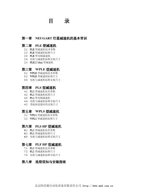
目录
公司简介
产品介绍 减速机专用名词解释………………………………………………………………………………………………… 减速机选型…………………………………………………………………………………………………………… 产品型号说明………………………………………………………………………………………………………… 减速机输入端联接方式………………………………………………………………………………………………
Tc2=Tr2 * fs≤Tn
侧倾力矩[Nm]:指轴向力和径向力作用于输出端轴承上径向受力点的力矩。其计算公式为:
轴向力F2AMax[N]:是指平行于轴心的一个力,它平行于输出轴,它的作用点与输出轴端有一定的轴向偏(y2)时,会形 成一个额外的弯挠力矩。轴向力超过样本所示的额定值时,须用联轴节来抵消这种弯挠力 。 [如图所示]
加速扭矩T2B[Nm]:指工作周期每小时少于1000次时允许短时间加载到输出端的最大力矩。工作周期每小时大于1000次时, 须考虑冲击因素。T2B是周期工作制选型时的一个最大值,实际使用 中的加速力矩(T2b)必须小于T2B。否则会缩短减 速机的寿命。
紧急制动扭矩T2NOT[Nm]:指减速机输出端所能加载的最大力矩,这个力矩可在减速机寿命期内加载1000次,绝对不能超 过1000次。(T2NOT=2•T2B)。 空载扭矩TO12[Nm]:指加载到减速机上的以克服齿轮箱内的摩擦力的力矩。 最大扭矩T2max[Nm]:指减速机在静态条件或频繁启动条件下所能承受的输出扭矩,通常指峰值负载或启负载。 实际所需扭矩Tr2[Nm]:所需扭矩取决于应用场合的实际工况,拟选减速机的额定扭矩TN必须大于这个扭矩。 计算用扭矩Tc2[Nm]:会在选择减速机时被用到,可以由实际所需扭矩Tr2和系数fs,按以下公式得出
日本新宝 行星减速机

特点:为圆形法兰盘输出方式,具有经济实用,性价比高,精度高、钢性好、承载能力大、效率高、寿命长、体积轻小、外形美观、安装方便、定位精准等特点,适用于交流伺服马达、直流伺服马达、步进马达、液压马达的增速与减速传动。
应用领域:伺服减速机可直接安装到交流和直流伺服马达上,广泛应用于中等精度程度的工业领域。
如:精密机床、焊接设备、自动切割设备、包装设备、太阳能,工业机器人、印刷设备、精密测试仪器等自动化数控设备的应用。
性能和特点:KE系列精密伺服行星减速机提供了高性价比,应用广泛、经济实用、寿命长等优点,在伺服控制的应用上,发挥了良好的伺服刚性效应,准确的定位控制,在运转平台上具备了中低背隙,高效率,高输入转速,高输入扭矩,运转平順,低噪音等特性,外观及结构设计轻小。
使用免更换的润滑油,及无论安装在何处,都可以免维修操作全封闭式设计,并且具有IP65的保护程度,因此工作环境差时亦可使用。
配备电机LA LZ S LR LB LE LC L1(一级传动)L2(二级传动)L3(三级传动)2000W 145 4-M8 22(F7) 65 110(H7) 10 176 301.5 347.5 385.5 3000W 200 4-M12 35(F7) 80 114.3(H7) 10 176 317.5 357.5 395.5 4200W 215 4-M12 42(F7) 115 180(H7) 10 190 352.5 392.5 430.5配备电机LA LZ S LR LB LE LC L1(一级传动)L2(二级传动)L3(三级传动)3000W 200 4-M12 35F7 82 114.3H7 10 200 317 364 410 4200W 215 4-M12 42F7 115 180H7 10 200 317 384 410 7500W 235 4-M12 55F7 120 200H7 10 220 347 424 440。
机械设备行业周报:谐波减速器市场空间有多大?

[Table_ReportType][Table_StockAndRank]+86 61678586********************+86 10 83326753******************************************9号院1号楼100031[Table_Title]谐波减速器市场空间有多大?2020年11月23日本期内容提要:[Table_Summary][Table_Summary]本周专题:谐波减速器凭借其体积小、传动比高、精密度高等优势,除在工业机器人的小臂、腕部、手部等部件使用外,已经在高端数控机床、半导体制造设备、医疗器械、光伏设备以及航空航天等多领域广泛应用,且其应用行业有不断拓宽的趋势;目前,多关节机器人是谐波减速器下游最大应用领域,达到36.22%;其次为协作机器人,占比达到32.41%。
根据我们测算,全球机器人谐波减速器需求约为121.85万台,市场规模约为30.46亿元。
目前,我国机器人用谐波减速器需求约为42.19万台,市场规模约为10.55亿元。
至2024年我国机器人用谐波减速器需求有望达到77.72万元,对应的市场规模有望达到19.43亿元。
目前,全球谐波减速器70%左右的市场份额被日本哈莫纳科,此外日本新宝在全球谐波减速器市场中也占有一席之地。
国内谐波减速器的生产企业主要有绿的谐波和中技克美。
目前绿的谐波的产品性能已经接近国际先进,且盈利能力要强于哈莫纳科。
我们认为随着绿的谐波IPO产能逐步释放以及技术实力的进一步提升,公司有望进军全球谐波减速器第一梯队。
本周核心观点:(1)优先选择成长空间明确的主流赛道,优选竞争优势持续夯实的优质公司:光伏设备领域,政策有望超预期,高成长的贝塔叠加工艺更迭带动的设备更替需求,捷佳伟创等公司持续推荐;锂电设备处在行业扩容的大赛道上,行业景气度抬升,设备公司具备贝塔属性,持续关注克来机电、先导智能、诺力股份等;核电重启带动行业热度升温,重点推荐江苏神通;(2)受益监管政策强化,多个细分行业迎来行业空间扩容机遇,消防监管政策强化带动消防设施需求提升,重点推荐青鸟消防;受益建筑安全领域政策强化,建议关注减隔震行业,关注震安科技;受益国内安全生产政策执行力度强化,建议关注防爆电器行业,重点关注华荣股份;(3)工业制造业需求复苏,国内上半年工业车辆销量同比增长11%,9月叉车销量同比增幅达到55%,工业机器人10月份产量同比增长近38.5%,激光行业需求景气,仪表仪器迎自动化、智能化趋势,国产替代加快,重点推荐柏楚电子、川仪股份,关注锐科激光、埃斯顿、埃夫特、安徽合力等;(4)考虑空间和时间的匹配,我们继续重点推荐中密控股、安车检测、捷昌驱动、广电计量、华测检测等。
- 1、下载文档前请自行甄别文档内容的完整性,平台不提供额外的编辑、内容补充、找答案等附加服务。
- 2、"仅部分预览"的文档,不可在线预览部分如存在完整性等问题,可反馈申请退款(可完整预览的文档不适用该条件!)。
- 3、如文档侵犯您的权益,请联系客服反馈,我们会尽快为您处理(人工客服工作时间:9:00-18:30)。
齿面硬度轮类型:行星齿轮减速机额定功率:0.05-5.00(kw)型号:SHIMPO VRL系列
布局形式:同轴式输入转速:3000(rpm)类别:行星齿轮减速机
用途:减速机品牌:SHIMPO/新宝级数:1,2
产品特色
伺服马达专用小型减速机
「静音」「高刚性」减速机
静音
采用防振动、低噪音的行星减速机构造和斜齿轮。
能最大限度的发挥其强度,实现静音化。
高刚性
采用体制钢材直接进行本体的机械加工。
在小巧、坚固的本体中发挥出最大的输出扭矩。
长寿命
采用耐久性良好、磨耗少的高级润滑脂,
无需长时间保养。
安装方便
采用接合器连接法兰、无键拧紧轴套。
不仅适合各公司的伺服马达,且马达与减速机的安装方便。
丰富的减速比阵容
汇集了从1/3~1/100的14种类型的减速比。
能广泛运用于各个领域。