Cherry机械键盘MX轴官方资料
多模功能,不受拘束 CHERRY MX BOARD 3.0S三模无线游戏机械键盘

多模功能,不受拘束CHERRY MXBOARD 3.0S三模无线游戏机械键盘作者:***来源:《微型计算机》2021年第21期凭借低延迟技术的出现,目前越来越多的游戏玩家开始中意支持多模连接功能的外设产品,以达到不受拘束、桌面更为整洁的目的。
为了扩大市场占有率,老牌外设厂商CHERRY 也于近期推出了旗下首款支持USB有线、2.4GHz无线、蓝牙5.2的机械键盘——CHERRYMX BOARD 3.0S三模无线游戏机械键盘。
那么它的表现到底如何呢?金属外壳,加持幻光即便是CHERRY旗下的机械键盘统一以MX BOARD为名,但它们彼此之间的设计风格与血统并不相同,MX BOARD 5.0、MXBOARD 6.0、MX BOARD 8.0、MX BOARD 9.0以及近期推出的CHERRY MX BOARD 3.0S三模无线游戏机械键盘,它们彼此之间的设计可以说并没有太多的相似点。
从整体来看,CHERRY MXBOARD 3.0S三模无线游戏机械键盘采用了窄边框搭配全尺寸设计,并且造型略显方正,尺寸保持在430mm×140mm×36mm,不会显得过于宽大。
细节方面,经过磨砂处理的铝合金外壳让CHERRY MX BOARD 3.0S三模无线游戏机械键盘具备一定的分量,同时也进一步提升了它的整体质感与耐用性。
从侧面看,CHERRY MX BOARD 3.0S三模无线游戏机械键盘没有选用通体铝合金外壳的设计—其侧面部分采用乳白色塑料材质,与外壳选用的铝合金材质有区别,提供的观感颇具层次。
不仅如此,CHERRY MXBOARD 3.0S三模无线游戏机械键盘的侧面设计了一些小角度的变化,这让它能够提供更不错的视觉效果。
而在顶部,CHERRY MX BOARD 3.0S三模无线游戏机械键盘设计了一个USB-C 供电接口以及电源开关,方便玩家根据需要调整三模连接以及补充电量。
键帽方面,CHERRYMX BOARD 3.0S三模无线游戏机械键盘采用经双色注塑工艺制成的ABS键帽,其表面经过了类肤喷涂,能提供更细腻的手感,并且透光性不错。
mechanicalkeyboard机械键盘入门

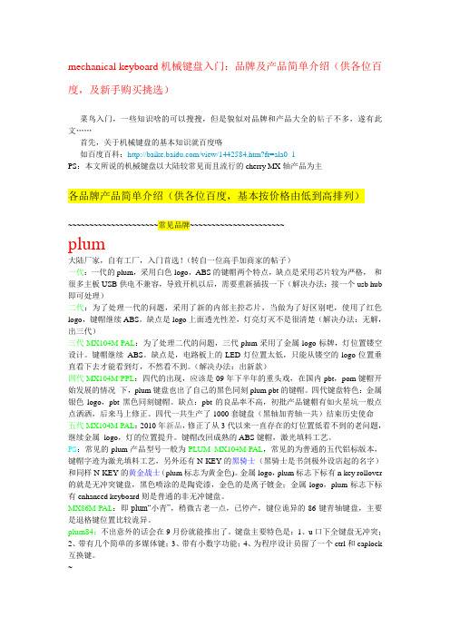
mechanical keyboard机械键盘入门:品牌及产品简单介绍(供各位百度,及新手购买挑选)菜鸟入门,一些知识啥的可以搜搜,但是貌似对品牌和产品大全的帖子不多,遂有此文……首先,关于机械键盘的基本知识就百度咯如百度百科:PS:本文所说的机械键盘以大陆较常见而且流行的cherry MX轴产品为主各品牌产品简单介绍(供各位百度,基本按价格由低到高排列)~~~~~~~~~~~~~~~~~~~~~常见品牌~~~~~~~~~~~~~~~~~~~~~~plum大陆厂家,自有工厂,入门首选!(转自一位高手加商家的帖子)一代:一代的plum,采用白色logo,ABS的键帽两个特点,缺点是采用芯片较为严格,和很多主板USB供电不兼容,导致开机以后,需要重新插拔一下(解决办法:接一个usb hub 即可处理)二代:为了处理一代的问题,采用了新的内部主控芯片,当做为了好区别吧,使用了红色logo,键帽继续ABS。
缺点是logo上面透光性差,灯亮灯灭不是很清楚(解决办法:无解,出三代)三代MX104M-PAL:为了处理二代的问题,三代plum采用了金属logo标牌,灯位置镂空设计。
键帽继续ABS。
缺点是,电路板上的LED灯位置太低,只能从镂空的logo位置垂直看下去才能看到灯,不然看不到。
(解决办法:出新款)四代MX104M-PPL:四代的出现,应该是09年下半年的重头戏,在国内pbt,pom键帽开始发展的情况下,plum键盘也出了自己的黑色同刻plum pbt的键帽。
四代键盘特色:金属银色logo,pbt黑色同刻键帽。
缺点:pbt的良品率不高,初批产品键帽有如火星坑一般点点洒洒,后来马上修正。
四代一共生产了1000套键盘(黑轴加青轴一共)结束历史使命五代MX104M-PAL:2010年新品,修正了从3代以来一直存在的灯位置低看不到的老问题,继续金属logo,灯的位置提升。
键帽改回成熟的ABS键帽,激光填料工艺。
cherry 樱桃键盘介绍

3、持久,由于关键部位为机械结构,稳定性比薄膜键盘强很多,理论寿命为单键2千万 次按压,黑轴为5千万次。
4、精致,键帽按久了都会打油,会变得比较滑也比较腻,刻印也会磨损,而现在市面上 机械键盘中高端都会采用POM或PBT材质,当然如果不是也可以买来一套键帽替换掉, 平时常用抹布擦擦注意清洁基本键帽会和键盘同寿命。
Cherry键盘的缺点
• 1、外观厚重、占地方。 • 2、设计古板。 • 3、打字声音响。
谢谢观看!
4
创始之人:默曼先生
2008年
2008年拜罗伊特分厂获得 了巴伐利亚洲经济、交通 和技术部颁发的巴伐利亚 质量奖。
3
2005年
公司获得了工业卓越奖, 被评为当年欧洲“最优的 工厂”
。
Cherry键盘的优点
1、轻盈,常见轴中最重的黑轴按键压力才为80g,力道大概为一根能弹5cm高的弹簧圆 珠笔。青、红、茶轴都为60g,所以即使是用黑轴,如果不是重度肌无力患者,长时间
Cherry键盘
从1990年到2005年他是德 国电子技术和电子工业中心 联合会的“开关和仪器安装 保”专业部的主席,并多年 担任该会技术委员会的主任。
1
1973年
1973年,默曼先生开始 就职于cherry公司的研发 部门,历经多个不同的重 要岗位。
2
2003年
他成为了公司总裁,对 cherry集团在欧洲的业务 全权负责。
Cherry MX8.0机械键盘 别样的精简之美
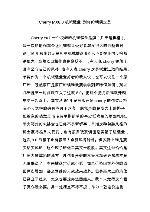
Cherry MX8.0机械键盘别样的精简之美Cherry作为一个极老的机械键盘品牌(几乎是鼻祖),每一次的动作都会让机械键盘爱好者激发很大的兴趣去讨论,16年放出的两款新型机械键盘8.0和9.0在业内反响都是挺大,当然众口相传也是褒贬不一,有人说cherry堕落了没有坚守自己的风格,也有人说cherry这是锐意进取的结果。
单纯作为一个机械键盘爱好者的我来说,也可以说是一个原厂粉,既然原厂是原厂的锅我就要尝尝到底味道如何,所以几乎是第一时间就在入了这款8.0。
把玩个把月后我就开箱感受一起奉上。
其实从60年纪念版开始cherry的包装风格我个人觉得的确有些过于浮夸,貌似走的是高大上的路子,但给我的感觉反而没有早期简单的牛皮纸盒来的更加扎实。
军火箱式的包装盒也已经不是新鲜事,早期这种包装风格的确会赢得很多人赞赏,也有很多玩家调侃是买箱子送键盘,这次8.0的箱子也有很多人点赞说各种好。
但实际上我是要实话实说的,这个箱子的做工其实一般般。
其实这也恰恰是厂家为难尴尬的地方,外包要是做的太好太精致必然成本是无限提高了,本来键盘定价就不低,如果价格因为外包的原因再次增加,那么骂娘的人就越来越多。
但是高大上的地位已经立了起来,怎么也要想办法圆起来。
我个人觉得这个箱子真心没必要。
另一处槽点不得不提,作为一款定价达到14**的键盘,附件几乎是没有的。
反观之前的60年款不但有轴体赠品还有清洁泥等小物件,国内代理这点上实在不应该不大气一点。
有时候温暖人的就是小小的一点产品上的关怀。
作为8.0键盘本体,发布会以后留个我个人的新奇点不多。
因为CNC已经被很多厂家品牌玩过了,原厂你还能玩出多少花样呢?说实话当时我是不太看好的。
加上被9.0的颠覆造型设计冲击过后对于8.0的心态已经是比较平缓的。
有时候惊喜就是来自平淡过后,8.0到手我才真的知道什么是大厂的态度。
CNC金属的外壳机械键盘我玩不少,有品牌的也有私人客制化的,还有来自棒子国的优秀作品,但多多少少在做工在完成度上都是有一些瑕疵的,但8.0真的有些不一样。
黑红青茶四种轴

cherry MX黑轴:MX黑轴是目前cherry旗下手感最重的MX轴,理论使用寿命为5000万次。
触发起始40g,终了80g的压力让习惯了薄膜键盘的玩家感很硬很重,不过在适应一段时间后可以发现MX 黑轴的短触发和快回弹很适合游戏玩家的快速点击的使用需求。
采用MX黑轴的按键在键帽下压过程中没有刻度和和触发感,给人的一种直上直下按压弹簧的感觉。
cherry MX红轴:据传MX红轴是cherry专为亚州人开发的一种无刻度感键轴,由于部分用户反应黑轴压力触发压力过重,感觉不太适合长时间使用。
所以cherry又推出了减压版的MX黑轴产品,这就是MX红轴。
MX红轴依旧保持着键程无刻度的特色,但是触发压力值同黑轴相比有所减轻,触发起始压力为30g,终了压力只有60g,相比于黑轴更适合文本录入等长时间使用。
MX红轴的理论使用寿命同MX黑轴相同,均为5000万次。
cherry MX青轴:MX青轴是被玩家称为最有机械感的键轴,触发起始压力为40g,终了压力为80g,按键触发时中有极其明显的刻度感,并伴有“咔嗒”的确认声。
有玩家形象的称基为“按圆珠笔的感觉”。
由于刻度凸起会在长时间使用中产生磨损,所以MX青轴的理论使用寿命与MX黑、红轴相比要短些,为2500万次。
MX青轴适中的压力和独特的刻度感较为适合文本录入人员使用。
不过MX青轴触发时会有一定的噪音,尤其是在快速文本录入时。
玩家如果对使用噪音有一定需求的话,建议不要选择MX青轴键盘。
cherry MX茶轴:有着“机械薄膜”之称的MX茶轴是四种键轴中最容易上手的一种。
起始40g,终了60g的触发压力可以让玩家无须适应即可使用。
按键触发时会有较为轻微的刻度感(快速使用时基本可以无视),但没有MX青轴的“咔嗒”声,使用声音比较轻柔,可以适应大部分用户的使用需求。
由于刻度感的原因,MX茶轴的理论使用寿命同MX青轴相同,均为2500万次。
国产黄轴:雷柏V7所采用的国产黄轴是以cherry MX轴为原型,并在使用键轴使用手感上重新进行调校,使其具有轻触发和高回弹速度。
机械键盘介绍

给大家介绍点机械键盘的知识机械键盘以超乎寻常的手感,经久耐用而为用户所推崇,提到机械键盘,往往代表着完美的手感,不菲的价格。
不过下面这三款近期促销的CHERRY机械键盘在价格方面略有优势,喜欢机械键盘的朋友可以留意一下。
国内比较常见的机械键盘很大一部分出于CHERRY,除了CHERRY原产机械键盘外,还有更多的机械键盘使用了CHERRY的键轴(Switch),提到CHERRY的键盘和键轴,足以代表出色的品质机械键盘的分层图示下面给大家介绍三款 CHERRY机械键盘G80系列是国内比较常见的CHERRY机械键盘,由于MX键轴分为四种颜色,再加上键帽等各个细节的制作工艺各有不同,G80系列产品种多。
CHERRY G80-3000LPCEU-0也就是大家所称的黑轴白色的G80-3000键盘黑轴键盘的logo和指示灯键盘支脚顶端有橡胶垫,可以起到很好的防滑作用正品行货签和键盘铭牌这款使用MX黑轴的CHERRY白色G80-3000键盘的网上报价是788元CHERRY G80-3000LPCEU-2(黑轴)黑色外观的G80-3000键盘,键面很简洁,logo都省略了这款机械键盘的型号为G80-3000LPCEU-2,和前一款略有不同的是,这一款使用了需要压力更小的黑轴,敲击时比上一款更为省力,喜欢较轻键入手感的用户可以考虑这一款。
CHERRY G80-3484HKCUS(茶轴)在G80系列中,3484机械键盘的做工要优于3000,接下来这款茶轴的CHERRY G80-3484HKCUS的报价要比3000高一些黑色外观防滑橡胶垫茶轴机械键盘敲击时声音较小,同时CHERRY生产的茶轴机械键盘数量相对较少,敲击手感比黑轴软,用户可以根据自身的使用习惯选用。
这款键盘的价格是1180 网上的报价Cherry前篇之MX Switch的简单介绍Cherry的机械键盘虽然已经存在了很久,但高质量伴随的高成本一直限制了它普及化的脚步,只是大多应用于一些专业领域。
Cherry ML轴和MX轴尺寸图

Technical specifi cationsElectrical characteristics Module ML Module MXSwitching voltage12 V AC / DC max.12 V AC / DC max.Switching current 10 mA AC / DC max.10 mA AC / DC max.Dielectric strength 500 V / 50 Hz 500 V / 50HzDurability at 5V, 1mA linear actuation –50 x 106Durability at 5V, 1mA tactile feel click20 x 10650 x 106Durability at 5V, 1mA alternate action–0,5 x 10⁶Durability at 5V, 1mA alternate action50 x 106Mechanical characteristicsContact confi guration Single-pole contact Single-pole contactAction Pressure point click Linear, pressure point click, alternate action, ergonomicActuator travel3,0 – 0,5 mm4,0 – 0,4 mm Impuls / 4,2 0,3 mm Rast / 4 – 0,5 mm clickPretravel1,5 ± 0,5 mm 2 ± 0,6 mm Impuls / 1,4 0,4 mm Rast / 2,2 0,6 mm clickInitial force30 cN min25 cN min.Actuation force45 ± 20 cN60 ± 20 cN linear a. Rast; 45 20 cN, ergonom. and 50 15 cN clickPressure point force50 ± 20 cN55 ± 20 cN, pressure point ergonomic / 60 15 cN pressure point clickBounce time during actuation with 0,4 m/s 5 ms 5 msStandard lead spacing18 mm (16 mm min.)19,05 mm (16 mm min.)Fastening Fixing pinsSnap fastening in frame or fi xing pins in the printed circuit boardin the printed circuit boardLighting (optional)–LED in red, green or yellowDecoupling diode–optionalWire jumper optional optionalMaterialsThermoplastics (min.UL 94 HB)Insulation materials Thermoplastics(min.UL 94 HB)Spring Stainless steel Stainless steelContacts High-quality gold alloy High-quality gold alloyOther CharacteristicsProtection class IP 40IP 40Operating temperature– 10 °C to +70 °C – 10 °C to +70 °CStorage temperature– 40 °C to +70 °C– 40 °C to +70 °CHumidity (without condensation) 5 % to 95 % 5 % to 95 %Soldering capability see soldering specifi cations see soldering specifi cationsFor detailed information and the layout of the details described above, please do not hesitate to ask for our technical specifi cations and drawing.67KEYMODULEFeaturesThe Cherry ML keymodule is a mechanical switching element using single-gap make contact element in Gold-Crosspoint contact technology. Its com-fortable actuation makes the module particulary suitable for low-cost con-struction of keyboards and keypads with great diversity and very low height.A multitude of different key cap shapes allows fl exible designs. Very short bounce time, reliable stroke, excellent tactile feeling and enormous cost-saving pave the way for a wide range of applications.Keymodule MLview direction “A”Reset pointf o r c e (c N )Operating pointPressure pointtravel (mm)Drilling pattern, view direction …A“68Keycaps and mechanicsKeycaps Keycap format Dimension X (mm)Bar Assembly number (mechanics + Bar)1 x 11 x 0,84––––––1 x 1,25–––1 x2 vertical25,6614-5007G99-1303 ZUB1,25 x 2 x 1 vertical 1,5 x 2 x 1,25 vertical 25,625,6614-5007614-5007G99-1303 ZUBG99-1303 ZUB1 x 1,5 1 x 1,53 1 x 1,75 1 x 21 x 2,2517,4517,4521,6525,630,65614-5004614-5004614-5005614-5007614-5009G99-1300 ZUBG99-1300 ZUBG99-1301 ZUBG99-1303 ZUBG99-1369 ZUB1 x 51 x 780,15116,15614-5006614-5010G99-1302 ZUBG99-1370 ZUB69KEYMODULEFeaturesThe constructive design of the key and the design of the associated key-caps fulfi l the ergonomic requirements for data input workstations. Long operating life with gold crosspoint contact and high reliability with quick actuation. Optionally with integrated colour LED decoupling diode or wire bridge. 4 mm actuation travel.Keymodule MXView of keymodule Drilling patternsKeyswitch assemblyLocking unitwith fi xing pinsand LEDwith fi xing pinswith fi xing pins and diode or wire bridgeSize of keycap1 x 21 x 2,251 x 2,75 1 x 3 1 x 8Type of keycap 8 mm / C yln 8 mm / C yln 8 mm / C yln …A“ (in mm)23,838,1133,35Part-No. (without Pins)G99-0224G99-0225G99-0226Part-No. (with Pins)G99-0742G99-0743G99-074470120f o r c e (c N )f o r c e (c N )f o r c e (c N )f o r c e (c N )travel (mm)travel (mm)travel (mm)travel (mm)MX-linear actuation MX with pressure point ergonomicMX with alternate actionMX with pressure point click Operating point Operating pointOperating pointPressure pointOperating pointPressure pointReset point Reset point Reset point Reset point Reset pointForce / travel diagramMultiple key mechanicalwith frameCutout of frame for keycaps sizes 1 x 2, 1 x 2,25, 1 x 2,756,65+0,14,6+0,213,5±0,1512,3±0,056,77±0,050,52,8+0,214±0,05“A”±0,14,2+0,1R 0,3max.R 0,3max.R 0,3max.3+0,1Cutout of frame for keycaps sizes 1 x 3, 1 x 7, 1 x 8, 1 x 9, 1 x 10Center line of moduleØ3,05+0,1Ø4+0,05“A”±0,17±0,115,24+0,113,5±0,1512,3±0,056,77±0,050,52,8+0,20,8+0,10,8+0,1“A”±0,114±0,056,65+0,14,2+0,1R 0,3max.R 0,3max.3+0,1PC-boardFaceplate Wire yokeHousingSupport bracket Keycap 8mm Keycap 8mmPC-boardWire yoke HousingSupport bracketSnapped Hooked1,5±0,14without frameDrilling pattern71。
mechanical keyboard机械键盘入门
mechanical keyboard机械键盘入门:品牌及产品简单介绍(供各位百度,及新手购买挑选)菜鸟入门,一些知识啥的可以搜搜,但是貌似对品牌和产品大全的帖子不多,遂有此文……首先,关于机械键盘的基本知识就百度咯如百度百科:/view/1442584.htm?fr=ala0_1PS:本文所说的机械键盘以大陆较常见而且流行的cherry MX轴产品为主各品牌产品简单介绍(供各位百度,基本按价格由低到高排列)~~~~~~~~~~~~~~~~~~~~~常见品牌~~~~~~~~~~~~~~~~~~~~~~plum大陆厂家,自有工厂,入门首选!(转自一位高手加商家的帖子)一代:一代的plum,采用白色logo,ABS的键帽两个特点,缺点是采用芯片较为严格,和很多主板USB供电不兼容,导致开机以后,需要重新插拔一下(解决办法:接一个usb hub 即可处理)二代:为了处理一代的问题,采用了新的内部主控芯片,当做为了好区别吧,使用了红色logo,键帽继续ABS。
缺点是logo上面透光性差,灯亮灯灭不是很清楚(解决办法:无解,出三代)三代MX104M-PAL:为了处理二代的问题,三代plum采用了金属logo标牌,灯位置镂空设计。
键帽继续ABS。
缺点是,电路板上的LED灯位置太低,只能从镂空的logo位置垂直看下去才能看到灯,不然看不到。
(解决办法:出新款)四代MX104M-PPL:四代的出现,应该是09年下半年的重头戏,在国内pbt,pom键帽开始发展的情况下,plum键盘也出了自己的黑色同刻plum pbt的键帽。
四代键盘特色:金属银色logo,pbt黑色同刻键帽。
缺点:pbt的良品率不高,初批产品键帽有如火星坑一般点点洒洒,后来马上修正。
四代一共生产了1000套键盘(黑轴加青轴一共)结束历史使命五代MX104M-PAL:2010年新品,修正了从3代以来一直存在的灯位置低看不到的老问题,继续金属logo,灯的位置提升。
- 1、下载文档前请自行甄别文档内容的完整性,平台不提供额外的编辑、内容补充、找答案等附加服务。
- 2、"仅部分预览"的文档,不可在线预览部分如存在完整性等问题,可反馈申请退款(可完整预览的文档不适用该条件!)。
- 3、如文档侵犯您的权益,请联系客服反馈,我们会尽快为您处理(人工客服工作时间:9:00-18:30)。
Perfectiondown to the smallest detailCONTENTSFor many years, Cherry snap switches and keyboards have beensynonymous with quality and reli-ability. Cherry is a trademark of ZF Electronics GmbH, a leading supplier of electronic components. Whether in household appliances, industrial applications, vehicles or input sys-tems, electronic components ensure reliable operation as well as safety and comfort. Our Quality Assurance System is ISO 9001 and TS 16949-certifi ed and our Environmental Management is ISO 14001-certified.In our experience you need a little advice to get the best out of your switches. This is why we always start by asking users for detailed information on the intended scope of application, its basic conditions and all associated speci-fi cations and data. We regard this as an absolutely indispensable fi rst step. This catalogue is intended only as a reference document. No responsibility is taken for the correctness of the details. We reserve the right to make changes which are minor or serve the purpose of progress.The technical details relate only to the product specifi cations; product characteristics are not warranted. We reserve the right to make technical changes and adjustments due to changed delivery opportunities up to the contract signing. Only our general sales and delivery conditions apply. We will gladly send you these on request.2Philosophy 4Location and quality6Growth, innovation and environment 8Products 10Lexicon12Overview 22Snap switches24Sliding contact switches 62Keymodules66 Check list for switch requirements72Lean Production Award 2006Bavarian Quality Award 2008Winner 2005Kaizen 5S Award 2009Phi los oph y 3PHILOSOPHYWhat makes the difference between a good and an excellent technical so-lution? Reliability, the power of inno-vation, these are the foundations of success. But how can success be achieved? Is there a formula which can be transferred to all industries? We think there is. The quality of a total solution is determined by the quality of its compo-nents. A fault in a component which only costs a few cents can paralyse everything. Perfection down to the smallest detail is therefore the basisof our philosophy as a supplier of mechatronic components. Another is attuning the individual elements optimally to one another. Therefore, we see ourselves as our customers‘ active partner when it comes to developing new products.Our record proves we are right. For many years, Cherry snap switches and keyboards have been synonymous with the highest quality and reliability. This principle has also made us one of the leading suppliers of electronic components. Regardless of whether you use our products in household appliances, industrial applications, in the automobile industry or for input systems – you can rely on safety and comfort in addition to reliable perfor-mance.It’s not the size which determinesthe power, but rather each individual component.45LOCATION AND QUALITYCustomer satisfaction grows with quality.And quality with closeness to the customer.With ever-shorter product cycles, the development time for new products is also being reduced. In order to guarantee maximum quality, close cooperation among all partners is important. We interpret the term “close cooperation” in an old-fashioned way – and wherever possible, we prefer personal contact with our partners.6To be as close to our customers as possible was the principle of Cherry Electrical Products Corporation, which was founded in the USA in 1953.In 1964 we established a subsidiary in Germany and in 1972 in England.Additional European subsidiaries followed in France and Czech Republic in 1985 and 1992, respectively. Today, the company acts on a global basis – with sites throughout the world: in North America and Europe as well as in Asia and Australia. Proximity on location allows us to react quickly to regional or individual requirements. We continue this philosophy while integrating the Cherry trademark in ZF Electronics GmbH. Being part of a worldwide network, we can thus be even more responsive to customer and market requirements.6 723145119128101. ZF Electronics GmbH2. ZF Electronics UK Ltd.3. ZF Electronics France S.a.r.l.4. ZF Electronics Klasterecz spol. s.r.o.5. ZF Electronics Offi ce Italy6. ZF Electronics Corporation7. ZF Electronics de Mexico8. ZF Electronics Offi ce Australia9. ZF Electronics Asia Limited10. ZF Electronics Offi ce Japan11. ZF Electronics TVS India Private Ltd.12. ZF Electronics (Zhuhai) Co. Ltd.7GROWTH, INNOVATION AND ENVIRONMENTCustomer satisfaction grows by quality. And quality by closeness to the customerGrowth and success across more than 50 years are no accident, but the result of a sustainable company strategy. A strategy which is applied equally to customers, employees,our own products and the environ-ment. This guarantees that our inno-vations will fall on fertile ground in the long and short term – and it will en-sure growth for us and our partners.Quality and environmentFor us, environmental consciousness is more than the fulfi llment of a duty; we live it every day. Therefore, years ago we introduced an integrated man-agement system based on the ISO 9001, ISO 14001 and TS 16949 stand-ards, whose quality and environmental standards have become second nature for our employees. In order to comply we must fulfi ll and even exceed the requirements of our customers, suppliers, investors, employees and, last but not least, the public, through consistent process orientation. This is alsoone of the reasons why our company has been honored with several awardsin recent years.Quality guidelineCustomer satisfactionIn the context of a cooperation based on partnership and trust it is ourmajor objective to fully live up to our customers' expectations.CompetitivenessWe can ensure ZF’s long-term corporate success by providing innovative,high quality, and cost-efficient solutions for a global marketSense of responsibilityThe prerequisites for achieving optimum working results are a distinctawareness of quality as well as assuming responsibility both for oneselfand for the Group.8Principles of environmental protectionCherry products are contributing to the technical progress on a global basis. However, this also means that the company has a responsibility to continuously improve the environmental compatibility of its products over their entire life cycle and to reduce the strains placed on natural resources.The Environmental Policy is checked regularly and is binding for all em-ployees. It is based on the following principles:1. We design our products and production processes in as energy and resource-effi cient a manner as possible. We use state-of-the-art environ-mentally friendly technologies whenever investments are made.2. We put appropriate measures into place to ensure that environmen-tally damaging incidents are avoided wherever possible and properly contained in the event of any incident. We comply fully with all relevant environmental directives.3. We involve our employees in the development and implementation of our environmental policy. We regularly train and motivate them so that they can actively assist in shaping our environmental protection policy.4. We are continuously improving operational environmental protection. Our suppliers are taken into account during this process.5. We implement the objectives we set ourselves right around the world with the assistance of appropriate management systems, we check the agreed performance levels on a regular basis and, if any discrepancy is detected, respond rapidly with appropriate remedial action.6. In matters relating to environmental protection, we engage in dialogue with customers, suppliers, authorities, and all local interested parties. Furthermore, we regularly report on the consequences of our activitiesEmployee satisfactionZF’s effi ciency is determined by our highly motivated staff. By involving all stakeholders and continuous communication, our employees' satisfaction can be maintained on a permanent basis.Process-oriented management approachApplying effi cient processes with balanced interaction to achieve highest product and service quality – that is the basis for our management system.Partner supplierOur suppliers make an essential contribution to the quality of our products. In order to achieve common quality objectives we cooperate with our sup-pliers as partners.Permanent improvementThe principle of continuous improvement is an important element of our actions and secures corporate success for the future.9PRODUCTSDiversity generates options.Options result in exactly solutions foryour requirements.Higher, faster, further – the demands for technical developments are increasing, while their size is being reduced. A challenge also for the engineers of the indi-vidual components. To fulfi ll both the requirements and the unusual demands of our partners, we have created a broad spectrum of switches. Decades of ex-perience in the development and manufacture of switches equates to the best solution for your application. The following pages present a detailed overview of our ranges, which are divided into three types of switches. But in addition to the switches presented here, we offer several other broad product lines, including electronic controls, mechatronic assemblies, sensors and rocker switches.10From single components to electronic assembliesMechatronicsExperience our compe-tence concerning controlunits and electronicassemblies – from cook-tops and fl ow-heaters tomany other applications.SensorsGet informed about ourstandard program ofsensors based on Hall-and Reed-technology.Rocker switchesOur rocker switch rangecovers device switchesto be used for examplein household appliancesand power tools as wellas for machinery andequipment.Key modulesRead up on our keymodules enabling fl exibledesign of keypads andkeyboards.Depending on the keycap, different lead spac-ings are also possible.Selector switchesInformation on our rangeof selector switches isavailable on our websitewww.cherry.de underthe category Switchesand Controls.More information on solutions concerning our range of mechatronics, sen-sors and rocker switches can be obtained from our respective product cata-logues. These can be either ordered as a printed copy from us or simplybe downloaded as PDF fi le on www.cherry.de.ActuatorApplying force to the actuator of a snap switch releases the snap-actionmechanism, which in turn triggers the switching operation.Auxiliary actuatorIt is possible to attach an auxiliary actuator to a snap switch in order to meet the specifi c requirements of a given application. Doing so usually alters the travel and forces involved in the switching operation, depending on the length of the levers. By attaching an appropriate auxiliary actuator, it is possible to increase travel and/or reduce the actuating force required.TerminalsCOM (Common = 1):Base terminalNC (Normally Closed = 2): The contact is closed in the rest position, thatis, the terminal is connected to COM. When the switch is actuated, the contact opens.NO (Normally Open = 4): The contact is open in the rest position, thatis, the terminal is separated from COM. When the switch is actuated, the contact closes.Contact gap(contact opening distance)The contact gap is the distance between a pair of open contacts. For snap switches, it is usually around 0.3 mm. Generally speaking, for switches with contact gaps < 3 mm, additional measures arenecessary for separation from the mains. These switches bear the mark µ for European approvals. Switches with a contact gap > 3 mm can general-ly be used directly for separation from the mains. Please check the device specifi cations applying to your particular product, and if there is any doubt, please clarify with the responsible testing agencies.Clearanceand creepage distanceClearance is the shortest distance through the air between two electrically conductive parts or between an electrically conductive part and a metal foil affi xed to an accessible surface of some insulating material. The creepage distance is the shortest distance along the surface of an isolating material between two electrically conductive parts or between an electrically con-ductive part and a metal foil fi xed to an accessible surface of the insulating material.LEXICONSnap Switches –Defi nitions and descriptionsSnap switches are activated by a spring-operated (or “snap-action“) mechanism. Depressing the actuator triggers the switching operation, with a pre-defi ned force and travel. Theswitching speed itself is largely inde-pendent of the speed of actuation.Auxiliary actuator ActuatorSilver- or “GoldCrosspoint” ContactNC-terminal (2)NO-terminal (4)COM-terminal (1)Graphical symbolsDescriptionFunctionGraphicalS.P .D.T .Single Pole Double Throw (Changeover contact)In rest position the COM terminal is connected to the NC contact. When the actuator is depressed, COM and NC break contact and COM and NO make contact. S .P .S.T. - N.O.Single Pole Single ThrowNormally Open (Make contact)When the switch is actuated, contact is made.S .P .S.T . - N.C.Single Pole Single ThrowNormally Closed (Break contact)When the switch is actuated, contact is broken.LEXICONActuator positionsDimensions for actuator positions are always specifi ed in relation to a given reference line.Rest positionThe rest position is the position of the actuator when no external force is being applied. Sometimes referred to as the “free position”.Operating point (mech.)The point along the actuator’s travel path at which the spring-operated mechanism is actuated.Final position (total travelled position)The position of the actuator at the end of its travel.Reset point (mech.)The point along the actuator’s path, as it travels back to its rest position, at which the spring-operated mechanism snaps back to its original posi-tion.Actuator travelPretravelThe distance travelled between the actuator’s rest position and the switching point.OvertravelThe distance travelled between the switching point and the end position. To make absolutely sure that the switching operation takes place, an actu-ator should use up at least 50 % of the available overtravel.Reset travelThe distance travelled between the end position and the release point. Free travel (open circuit travel)The distance travelled between the reset point and the rest position.Total travelThe sum of pretravel and overtravel, or of reset travel and free travel.Movement differentialThe distance travelled between the operating point and the reset point.Positions,forces and travelsP r e t r a v e lRest positionActuator HousingOperating positionFinal positionReset positionM o v e m e n t d i f f e r e n t i a lR e s e t t r a v e lF r e e t r a v e lT o t a l t r a v e lO v e r t r a v e lForcesInitial forceThe force required to move the actuator away from its rest position.Operating forceThe force required to move the actuator through the operating point.Sustaining forceThe force required to hold the actuator in its fi nal position.Reset forceThe level to which the operating force must be reduced to allow the spring-operated mechanism to return to its original position.Differential forceThe difference between the operating force and the reset force.Conversion US-UnitsInch / millimeterGenerally, measures in this catalogue are based on the metric system andindicated in millimeter (mm). For the conversion please use the following relation:1 millimeter = 0.03937 inchesExample: 27.8 mm x 0.03937 = 1.094 inches And for the reverse calculation:1 inch = 25. 4 millimetersExample: 0. 51 inches x 25.4 = 12.95 mm ForcesThe specifi cations of the operating force for the switches are indicated in hundredth Newton (cN). For the conversion please use the following relation:1 Newton (N) = 100 cN = 101.972 gf 1 cN = 1.01972 gf Example: 250 cN x 1.01972 = 254.93 gf The re-conversion corresponds to:1 gf = 0.981 cN,Example: 850 gf x0.981 = 833.85 cNDiagram showing relationship between operating force and travel Final positionOperating pointReset pointS u s t a i n i n g f o r c eO p e r a t i n g f o r c eR e s e t f o r c eI n i t i a l f o r c eD i f f e r e n t i a l f o r c eMovement differentialOvertravel Reset travelPretravel Free travelTotal travelOperating pointPretravel Reset pointN .O .N .C .Free travelOvertravel Movement differentialReset travelTotal travelRest positionFinal position Diagram showing relationship between contact force and travelLEXICONOperating lifeThe operating life specifi es the minimum number of switch cycles within the specifi c values. It depends on a large number of parameters thatare determined by the intended application case. Among these are, for example:⏹switched current and switching voltage⏹type of load (e.g. ohmic, inductive or lamp load)⏹Combination of materials in actuating element/actuator⏹Actuator type⏹Actuator speed⏹Switching frequency (switching cycles / min)⏹Pretravel / Overtravel⏹Environmental factors such as climate conditions or harmful gases(e.g. SO2)Please note:Media such as greases, oils and materials which contain silicon must not be used on the switch. There is a distinction between mechanical and electrical operating life.Mechanical lifeIndicates how often a switch can be actuated without an electrical load. Mechanical endurance is calculated by actuating the snap switches axially in relation to the actuator in a sinusoidal pattern using about 80 % over-travel at a switching frequency of 4 Hz at room temperature.Operating life, temperature resistance, vibration and electric resistanceElectrical lifeThe selection of the optimal contact material has great infl uence on the operating life. The electrical life test is conducted at rated voltage, rated current and resistive load at 23 °C ambient temperature. The lower the electrical current, the longer the electrical life – under some circumstances it may even equal the switch’s mechanical life.Please note:For switching loads which deviate from the values specifi ed in the cata-logue, we recommend that you discuss the issues involved with Cherry. This is especially important if you are using other loads as linear resis-tances. These can be electrical circuits with inductive resistances (mo-tors), capacitive resistances (condensers) or lamp loads. To ensure thata switch reaches the maximum of its electrical operating life, the switch should not be subjected to pressure in its rest position (pre-stressed) and at least 50 % of the available overtravel must be used. Operating life specifi cations for direct current loads are available on request. Where higher switching capacities are involved, we recommend the use of fuses to provide protection against arcing.Please note:Since the operating life of a snap switch depends on a number of factors, we recommend that fi eld trials be performed in order to establish the likely electrical life of a switch in a given application. This is especially recom-mended when the application deviates considerably from the test condi-tions described above. Our specialists are always ready to provide you with more advice regarding possible solutions for your particular application. Behaviour atdifferent temperaturesDepending on the model, the operating temperatures of our switches range from -25 to +70 °C and -40 to +150 °C. If you attempt to use a switch at operating temperatures either above or below those recommended for your particular model, the switch‘s material properties will change andits reliability will be affected. Where switch model codes start with “T” (e.g. 40T125 in compliance with EN 61058), the switches involved have been approved for use at the corresponding temperatures.Vibration andshock resistanceSnap switches are naturally fairly resistant to shocks and vibrations thanks to their minimal mass of moving parts. They are at their most resistant when the actuator is in the rest position or end position, when vibration resistance is as high as 5 g at 20 – 200 Hz while shock resistance attains 50 g (6 ms).Please note:Snap switches are more susceptible to vibrations at the switching point and at the release point. In certain conditions, this could result in transient make or break contacts (bouncing) to the detriment ofthe switch‘s operating life. This is why snap switches which are regularly exposed to vibration should, wherever possible, not be actuated slowly. Electric strengthThe electric strength of our snap switches – in the case of models suited for mains voltages – exceeds 1500 V AC between conducting parts and the earth and 750 V AC between the terminals (open contacts) measured over a period of one minute at an ambient temperature of 23 °C ± 5 °C, relative humidity of < 70% and normal atmospheric pressure.LEXICONOperating speedSnap switches are suitable for a broad spectrum of operating speeds. How-ever, extremely slow or fast actuations can affect the switch performance and operating life. For product-specifi c values, please see the technical specifi cations. The maximum switching frequency (switchings/s) is limited by the electric load. With low switch loads, up to 10 actuations per second are possible.Please note:Sudden actuation must be avoided since it decreases the mechanical operating life.Contact bounceBounce time is the time between the moment closing contacts fi rst touch and fi nal (defi nitive) contact closure. The typical bounce time for our snap switches is between 1.5 and 3 ms, depending on the series.Transit timeIn two-way (double-throw) switches, transit time is the time betweenthe moment the break contact element (NC contact) fi rst opens and the make contact element (NO contact) fi rst closes. Transit time is generally determined by design features such as e. g. contact travel and elastic characteristics.It generally varies between 3 and 10 ms, depending on the model.Please note:If transit time is critically important to the functioning of your applica-tion, don‘t hesitate to contact us.ContactsWe supply switches with standard and crosspoint contact technology. For low-voltage and low-current applications, we strongly recommend the use of gold crosspoint contacts. The reduced surface area of the cross-shaped contacts means that the surface pressure is greater, which in turn enhances reliability. Standard contacts are more suitable for higher switched loads. Contact materialsGold and gold alloys: primarily AuAg; AuAgPtSilver and silver alloys: primarily AgNi; AgSn02Gold alloys are especially suitable for low currents and voltages. Typically they are used in the range from 5 V, 1 mA DC to 12 V 100 mA DC. But it may also make sense to use them in switches which are only occasionally operated or in atmospheres with a high sulphur content.For switching heavier loads, it usually makes sense to use silver or silver alloys. In this case, the range typically extends from 12 V, 100 mA DC to 250 V 21 mA AC.Please note:Because choosing the right contact materials depends on a large number of factors, such as switching voltage and current, operating environment, atmospheric conditions, etc., we are always pleased to advise you on the best choice of material for your application. Before making any fi rm deci-sions, we do advise you to carry out fi eld trials of our switches in real-life conditions.Operation, contact types and materialsMaterialsFor our standard switches, we use high-quality, cadmium-free plastics which are optimized for the intended application. As a rule, we seek to avoid the use of toxic or hazardous materials. You can fi nd out more about our materials policy by consulting our hazardous substances exclusion list. Behaviour of materials in fi reInsulating materials which are directly connected to electrically conduc-tive parts are classifi ed according to their degree of fl ammability. Most of the materials we use to manufacture housings are self-extinguishing and categorised under the UL 94 V0 standard.Tracking resistanceMost of the insulating materials we use in our snap switches have a proof tracking index of PTI 250 (PTI 300, e.g. D4) or PTI 175 (PTI 250, e.g. DB, DC). This means that they are capable of 50 drops of test fl uid at a test voltage of 250 V without producing any leakage current (IEC 60112). RoHSSwitches without leads already conform to RoHS. Switches with leadsare available in RoHS-conforming models on request. In case of further processing with lead-free soldering, the product-specifi c solder recommen-dations must be heeded.Glow wire testThe insulation materials used for snap switches with ENEC approval fulfi l the required fi lament tests GWFI according to the household appliance standard IEC 60335-1 at 850 °C and GWIT at 775 °C or alternatively the fi lament test GWT at 750 °C.Contact resistanceThe contact resistance of snap switches is composed of the contact resis-tance and the resistance of the conductive parts. It depends primarily on the construction and the contact material. The contact resistance of silver contacts is max. 100 m, of gold contacts max. 50 m when they are new. Insulation resistanceThe insulation resistance between the conductive parts of our snap switches and a conductive underlay or between the open contacts exceeds 10 M when they are new, measured over a period of one minute at room tem-perature with 500 V DC.Caution: humidity and soiling can decrease the insulation resistance.Materials andcontact resistanceDesignationsASA Acrylonitrile-styrene-acrylicesterLCP Liquidcristal polymerLSR Liquid silicone rubberPA PolyamidePBT PolybutyleneterephthalatePET PolyethyleneterephthalatePOM PolyacetalPPHS Polyphenylene sulphidePPS Polyether sulphoneSI SiliconeTPE Thermoplastic elastomerVMQ Vinyl-methyl-polysiloxaneDegree of fl ammability In vertical fl ammability test,goes out after no more than Drops of molten materialcapable of igniting waddingMax. durationof afterglowUL ICE / VDEV-0FV-0 5 seconds no30 seconds V-1FV-125 seconds no30 seconds V-2FV-225 seconds possibly60 seconds HB FH Burning rate in horizontal fl ammability test: up to 3 mm thick < 7.5 mm/min;over 3 mm thick > 3.8 mm/minLEXICONApprovalsENEC -VDEENEC -KEMAUL USAUL USA and CanadaRemarkENEC is the abbreviation for »European Norms Electrical Certifi cation«. The ENEC mark is a common European safety certifi cation mark, based on testing to harmonized European safety standards and includes switches for appliances in accordance with EN61058.Degree of protectionDegrees of protection are expressed in terms of compliance with IEC 60529. They are designated by the letters IP followed by two numbers. The fi rst number indicates the extent to which the switch is protected against contact with live parts and the ingress of solid parts; the second number indicates the extent to which it is protected against the ingress of water. For the most part, our switches are covered by the following types of protection.IP00 No special protectionIP40 Protected against access solid foreign objectsof 1 mm diameter and greaterIP50 Dust-protectedIP65 Dustproof and protected against fl owing waterIP67 Dustproof and protected against short-term immersionApprovals, markings and protectionSwitch markings (Example)EN 61058-110 A(3)A250 V~µ40T855E4Rated current resistive load Rated currentmotor loadRated voltage Microdisconnectioncontact gap< 3 mmRated ambienttemperature(– 40 °C to +85 °C)Operation cycles50.000UL 105410 A1/2 HP125-250 V ACRated current inductive load Rated currentmotor loadRated voltage。