Compactlogix的基本实验,Studio5000软件的使用方法
AB PLC编程软件RSLOGIX5000入门2——组态 IO
AB PLC编程软件RSLOGIX5000入门2——组态 I/O现在我们将进行项目的 I/O 组态。
要与 I/O 模块通信,必须将模块添加到 I/O Configuration 文件夹中。
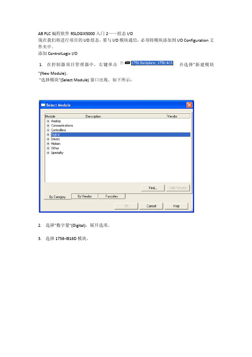
添加 ControlLogix I/O1. 在控制器项目管理器中,右键单击并选择"新建模块"(New Module)。
"选择模块"(Select Module) 窗口出现,如下所示:2. 选择"数字量"(Digital),展开选项。
3. 选择 1756-IB16D 模块。
4. 单击"确定"(OK)。
软件将要求您选择模块的主版本。
5. 选择"主版本"(Major Revision) 2 并单击"确定"(OK)。
将出现 1756-IB16D 的"模块属性"(Module Properties) 向导。
模块组态向导只要向系统中添加 I/O 模块就需要通过模块组态向导。
该向导允许您逐步通过某个模块所需的整个组态。
您稍后可以通过在 I/O Configuration 文件夹中双击相应模块或通过标签监视器/编辑器访问此信息。
在 Logix 中,组态 I/O 模块不再需要 DIP 开关或跳线。
I/O 模块均通过软件组态。
在进行系统设置时这可节省时间。
所有模块的组态是控制器程序的一部分,而且这些组态可从控制器下载到模块中;从而能够在I/O 模块失效时进行轻松替换。
6. 输入"名称"(Name)、"插槽"(Slot) 和"电子匹配"(Electronic Keying) 参数,如下所示。
保留所有其它字段的默认值。
通信格式 (Comm Format)确定与模块关联的标签的数据结构。
许多 I/O 模块支持不同的格式。
每种格式使用不同的数据结构。
Compactlogix的基本实验,Studio5000软件的使用方法
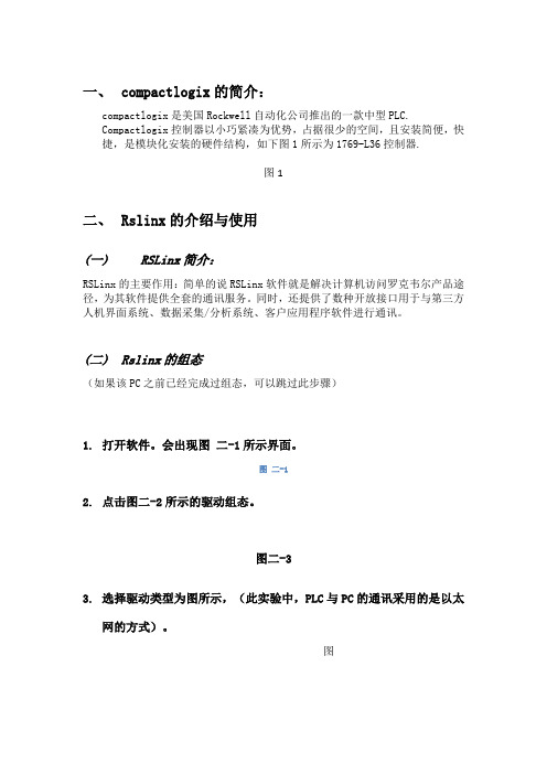
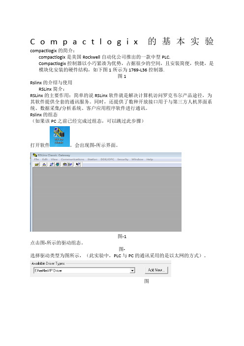
一、compactlogix的简介:compactlogix是美国Rockwell自动化公司推出的一款中型PLC.Compactlogix控制器以小巧紧凑为优势,占据很少的空间,且安装简便,快捷,是模块化安装的硬件结构,如下图1所示为1769-L36控制器.图1二、Rslinx的介绍与使用(一)RSLinx简介:RSLinx的主要作用:简单的说RSLinx软件就是解决计算机访问罗克韦尔产品途径,为其软件提供全套的通讯服务。
同时,还提供了数种开放接口用于与第三方人机界面系统、数据采集/分析系统、客户应用程序软件进行通讯。
(二)Rslinx的组态(如果该PC之前已经完成过组态,可以跳过此步骤)1.打开软件。
会出现图二-1所示界面。
图二-12.点击图二-2所示的驱动组态。
图二-33.选择驱动类型为图所示,(此实验中,PLC与PC的通讯采用的是以太网的方式)。
图4.然后点击Add New添加。
出现图所示,点击OK。
图5.在图中选择当前默认的“扫描本地子网”选项,然后点击确定。
图6.以上步骤我们已经完成了RSLINx的组态,我们可以在RSwho中查看连接情况,单击左上角RSwho,出现图所示图画。
(在ETHIP-3中展开我们可以看到与本地子网相连接的设备)图三、编程软件studio5000的使用(一)打开studio5000 软件在安装有studio5000软件的计算机上,用鼠标依次点击“开始\所有程序\Rockwell Software\Studio5000”或者双击桌面上Studio5000的图标打开。
Studio5000的主界面如图所示。
图3.1(二)创建一个新的控制器文件创建一个新的控制器文件的具体步骤如下:7.在Create菜单下选择New Project。
如图。
图3. 2-18.选择控制器型号。
本次试验使用的是CompactLogix 5370 Controller下的1769-L36ERM系列。
Logix5000 软件PLC培训使用手册

AB -Logix5000 PLC 使用培训教程目录第一章AB PLC使用介绍第一节 BOOTP软件的应用以太网模块在第一次使用时里面没有IP地址,只有物理地址即MAC地址,需要用户给以太网模块分配IP地址。
现在来介绍如何用BOOTP软件给以太网模块设置IP地址。
注意只有没有IP地址的以太网模块才可以用BOOTP软件,如果已经有了IP地址修改IP地址,BOOTP软件是不适用的。
按如下步骤1、找到BOOTP软件可以在RSLogix5000软件的TOOLS里找到也可以在开始菜单里找到如下图在使用bootp软件之前要把本地网络IP地址设置成固定IP和最终想设置的以太网模块地址是同一个网段。
不能是自动获取。
2、然后打开BOOTP-DHCP-Server出现如下图所示,白色对话框里是自动扫描到的MAC地址。
3、然后双击MAC地址会出现如下4、在IP地方输入IP地址5、点击OK出现如下图6、使IP地址部分高亮然后电机按钮直到Status处出现commad successful此时已经把以太网模块的IP地址设置成动态的,断电后还会丢失(注意:有时候需要点击多次才能成功是正常的)然后在点击按钮,直到Status处出现commad successful此时IP地址已经设置成静态的。
7、用BOOTP设置IP地址完毕第二节RSlinx通讯软件介绍RSlinx是通讯软件,用于建立PLC和PC之间的通信。
下面我们将介绍通过DF1通信协议以及ENthernet IP协议,建立计算机和PLC的通信。
一、通过DF1通信协议建立计算机和PLC的通信步骤如下:1.打开RSlinx,可以按如下的路径打开,或者是直接点击右侧任务栏下的图标。
RSlinx打开后出现如下界面:2、打开RSlinx后,直接点击图标,即上图标注出的Configurate drives,或者是通过Communications>Configurate drives,3、将下拉箭头展开,出现如下界面:4、选择RS-232 DF1 devices,然后选择Add New按钮,点击OK5、注意在Comm下,若是编程电缆直接和电脑的串口相连,则用默认的COM1,若是采用了USB转串口,则需根据实际情况选择相应的串口,确认Comm,如下图所示。
RSLOGIX_5000教程 中文帮助

RSLOGIX 5000实例教程首先你要给PLC的处理器定义,定义的内容有名字、类型、机架的背扳所在槽号、创建的文件路径等。
这里处理器类型选1756 L1 controllogix 5550,名字定为PLC,description定为练习,背板定为13槽,槽号0槽,路径默认。
图 1-2点击ok完成设置,显示RSLogix5000工程界面1.首先提出tag(标签)的概念,标签:就是实际工程中的变量,有模拟量如水位、压力、温度。
数字量如开关启停、状态显示等。
我们在程序中使用它进行编程,在窗口中在线查看状态,也可以向上位机输出标签值。
2.标签类型一 base 基本类型包括: 1 BOOL 布尔型 1 BIT2 SINT 短整型 1 BYTE3 INT 整型 2 BYTE4DINT 双整型 4 BYTE5REAL 实型 4 BYTE二 STRUTURES 结构体类型 1 predefined 预定以型图 1-3User-defined 用户定义型:本例以自定义PUMPPARAMETERS为例在其中定义结构体成员分别为ACCTIME,RUNTIME,SEQUENCE,STATUS,FIRSTPUMP,并确定各自类型。
图 1-4用户可以利用标签名称来引用结构体内的成员,格式为:tag_name.member_name。
如果结构体定义为数组,则使用数组标签,后面是在数组中的位置(position)和子结构体(substucture)及成员名称(member)。
格式为:array_tag[position].member。
下面介绍一下别名标签的概念:用于表示其它标签的标签,在为结构体元素或数组定义简化标签名称时很有用。
用户可以使用标签编辑器来创建一个别名,或者在你输入逻辑并且利用新标签(new tag)对话框定义别名时输入别名标签。
见图1-5图1-51.在标签编辑器中选择需要建立别名的标签以alarm 为例可以直接在alias下输入别名,也可以在空白处点右健,在弹出的菜单中选edit tag properties,图1-6标签作用域:用户可以在一个单独的程序中队标签进行分组,或使标签在控制器范围内对指令开放。
RSLogix Emulator 5000 手册
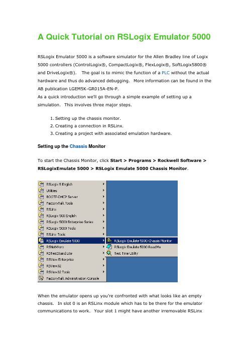
A Quick Tutorial on RSLogix Emulator 5000RSLogix Emulator 5000 is a software simulator for the Allen Bradley line of Logix 5000 controllers (ControlLogix®, CompactLogix®, FlexLogix®, SoftLogix5800® and DriveLogix®). The goal is to mimic the function of a PLC without the actual hardware and thus do advanced debugging. More information can be found in the AB publication LGEM5K-GR015A-EN-P.As a quick introduction we’ll go through a simple example of s etting up a simulation. This involves three major steps.1.Setting up the chassis monitor.2.Creating a connection in RSLinx.3.Creating a project with associated emulation hardware.Setting up the Chassis MonitorTo start the Chassis Monitor, click Start > Programs > Rockwell Software > RSLogixEmulate 5000 > RSLogix Emulate 5000 Chassis Monitor.When the emulator opens up you’re confronted with what looks like an empty chassis. In slot 0 is an RSLinx module which has to be there for the emulator communications to work. Your slot 1 might have another irremovable RSLinxmodule depending if you are running RSLogix Enterprise.From here we set up our hardware configuration for simulation. Our first step will be to add the CPU. In this case it is a special one called an Emulation Controller.1.Click Slot > Create Module.2.Choose the Emulator RSLogix Emulate 5000 Controller.3.Chose slot 2 for the controller4.Click OK to add it to the chassis monitor.5.At this point you may be accosted with a message about previousconfigurations. Just select Reset the Configuration to Default Valuesand click NEXT.6.The next two dialog screens are for setting up the controller details. ClickNEXT and FINISH to accept all the defaults.Next we’l l add some input/output simulation.1.Click Slot > Create Module.2.Choose the 1789-SIM 32 Point Input/Output Simulator.3.Chose slot 3 for the simulator and click OK.4.Accept the defaults for the setup by clicking NEXT and FINISH.The chassis monitor will now have two emulation modules in it ready to go.Creating a connection in RSLinx1.Start RSLinx under Start > Programs > Rockwell Software > RSLinx >RSLinx Classic2.Click Communications > Configure Drivers.3.Select the Virtual Backplane (SoftLogix 58xx) driver from theAvailable Driver Types list.4.Click Add New. The Add New RSLinx Driver dialog box appears. Click OK.5.The new driver appears in the Configured Drivers list. Click Close.Using RSLogix Emulator in a ProjectTo use the emulator in a project you must setup the hardware correctly.1.Start the RSLogix 5000 software and create a new project.2.Under the New Controller window type select an Emulator – RSLogixEmulator 5000 Controller. Give it a name and assign it to the sameslot as the one you put in the Chassis Monitor which in our example is slot2. Click OK.3.In RSLogix 5000's Controller Organizer, right click on the I/OConfiguration folder, and then click New Module. The software displaysthe Select Module window.4.Open the Other folder. Select the 1756-MODULE from the modules listand then click OK.5.The software displays the New Module window.a. Add a Name for the card.b. In the Slot field put the number that corresponds with the ChassisMonitor.c. For the Connection Parameters put in the following and click OK6.7.8.On the next Module Properties screen make sure to change theRequested Packet Interval to 50.0 ms.Ready, Set, GoYou are now ready to use the emulator just like you would any other PLC. Open Who Active and set the path to the RSLogix 5000 Emulator.The inputs can be simulated in the emulator’s Chassis Monitor by right clicking on the module and selecting Properties. Under the I/O Data tab is the ability to toggle each of the inputs on or off.。
实验2_RSLogix5000软件应用2_CompactLogix v1.0
4.组织数据 10)右键点击 Controller Tags,选择 New Tag,新建标签数据。输入标签的名称、
描述(可选),选择标签类型和数据类型等,然后点击 OK。
Lab2.2- 12 -
Lab material for RSLogix5000
HuaZhang Electric Custom Training
请按步骤:
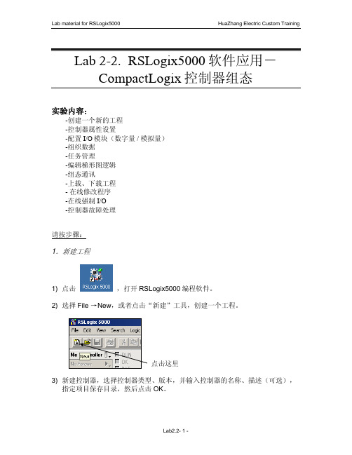
1.新建工程
1) 点击
,打开 RSLogix5000 编程软件。
2) 选择 File →New,或者点击“新建”工具,创建一个工程。
点击这里 3) 新建控制器,选择控制器类型、版本,并输入控制器的名称、描述(可选),
指定项目保存目录,然后点击 OK。
Lab2.2- 1 -
Lab material for RSLogix5000
Period:如果定义了任务类型为周期性,在这里设置任务的触发周期。 Priority:如果定义了任务类型为周期性,可以通过输入 1 至 15 的编号来指定任务
的优先级;编号越低,优先级越高。连续性任务的优先级最低,可以随时被 任何周期性任务中断。CompactLogix 控制器使用一个专用的、优先级为 7 的周期性任务处理 I/O 数据,这个任务以 CompactBus 总线扫描周期 RPI 时 间执行。 Watchdog:看门狗定时器用于监控任务的执行,它在任务启动时开始计时,任务 执行完毕后停止;如果达到预置的定时值,将产生一个主要故障。
选择 Fault /Program Action
该窗口用于定义模块在编程模式和故障模式下的输出状态。 CompactLogix 控制器不支持本地 I/O 模块保持最后状态或用户自定义安全状
态,如果一个本地 I/O 模块失效,例如,丢失与控制器的通讯,或者在带电的情况 下任何模块从系统总线上断开,控制器会进入故障模式,所有的输入将为 OFF 状 态。
RSLogix_5000_仿真软件使用方法(精)

A Quick Tutorial on RSLogix Emulator 5000RSLogix Emulator 5000 is a software simulator for the Allen Bradley line of Logix 5000 controllers (ControlLogix®, CompactLogix®, FlexLogix®, SoftLogix5800® andDriveLogix®. The goal is to mimic the function of a PLC without the actual hardware and thus do advanced debugging. More information can be found in the AB publication LGEM5K-GR015A-EN-P.As a quick introduction we’ll go through a simple example of setting up a simulation. This involves three major steps.1. Setting up the chassis monitor. 建立机架2. Creating a connection in RSLinx. 在 RSlinx 建立连接3. Creating a project with associated emulation hardware. 创建带虚拟控制器的项目 Setting up the Chassis MonitorTo start the Chassis Monitor, click Start > Programs > Rockwell Software > RSLogixEmulate 5000 > RSLogix Emulate 5000 Chassis Monitor.When the emulator opens up you’re confronted with what looks like an empty chassis.In slot 0 is an RSLinx module which has to be there for the emulator communications to work. Your slot 1 might have another irremovable RSLinx module depending if you are running RSLogix Enterprise.From here we set up our hardware configuration for simulation. Our first step will be to add the CPU . In this case it is a special one called an Emulation Controller.1. Click Slot > Create Module.2. Choose the Emulator RSLogix Emulate 5000 Controller.3. Chose slot 2 for the controller4. Click OK to add it to the chassis monitor.5. At this point you may be accosted with a message about previousconfigurations. Just select Reset the Configuration to Default Values and click NEXT .6. The next two dialog screens are for setting up the controller details. Click NEXT and FINISH to accept all the defaults.Next we’ll add some input/output simulation.1. Click Slot > Create Module.2. Choose the 1789-SIM 32 Point Input/Output Simulator.3. Chose slot 3 for the simulator and click OK.4. Accept the defaults for the setup by clicking NEXT and FINISH .The chassis monitor will now have two emulation modules in it ready to go.Creating a connection in RSLinx1. Start RSLinx under Start > Programs > Rockwell Software > RSLinx > RSLinx Classic2. Click Communications > Configure Drivers.3. Select the Virtual Backplane (SoftLogix 58xx driver from the Available Driver Types list.4. Click Add New. The Add New RSLinx Driver dialog box appears. Click OK .5. The new driver appears in the Configured Drivers list. Click Close .Using RSLogix Emulator in a ProjectTo use the emulator in a project you must setup the hardware correctly.1. Start the RSLogix 5000 software and create a new project.2. Under the New Controller window type select an Emulator – RSLogix Emulator 5000 Controller. Give it a name and assign it to the same slot as the one youput in the Chassis Monitor which in our example is slot 2. Click OK.3. In RSLogix 5000's Controller Organizer, right click on the I/O Configuration folder, and then click New Module. The software displays the Select Module window.4. Open the Other folder. Select the 1756-MODULE from the modules list and then click OK.5. The software displays the New Module window. a. Add a Name for the card.b. In the Slot field put the number that corresponds with the Chassis Monitor.c. For the Connection Parameters put in the following and click OK Assembly Instance Input Output Configuration 1 2 16 Size 2 1 0 6. 注意:按上表填,下图中显示的数不准确注意:按上表填,7. 8. On the next Module Properties screen make sure to change the Requested Packet Interval to 50.0 ms.(必须 50ms 以上,否则出错)以上,否则出错)(模块也行,(实际不仿真 I/O 模块也行,只要在 rslinx5000 中建 tag)) Ready, Set,Go You are now ready to use the emulator just like you would any other PLC. Active and set the path to the RSLogix 5000 Emulator. Open WhoThe inputs can be simulated in the emulator’s Chassis Monit or by right clicking on the module and selecting Properties. Under the I/O Data tab is the ability to toggle each of the inputs on or off. Note: RSLogix Emulator is sometimes erroneously called RSEmulator.。
Compactlogix的基本实验,Studio软件的使用方法
在Create菜单下选择NewProject。如图。
图2-1
选择控制器型号。本次试验使用的是CompactLogix5370Controller下的1769-L36ERM系列。
“name”栏,键入字母和数字组合作为名字,如“test”保存路径栏选择一个方便查找的文件夹,我们选择D:\Documents\Studio5000\Projects。然后点击“Next”。
图
出现如图所示梯形图界面。
图
添加输入元件,单击如图所示工具栏中的OTE 。
图
创建标签,如图所示,右键单击元件选择NEWTag。
图
标签的关联
如图所示,创建标签名为“switch”,数据类型为BOOL,然后在“Tyde”中选择:ALIas。
图
将该标签与输入模块的输入点I相关联,如图所示,点击Alias,在Local1:I下的data中选中“0”。(即表示标签“switch”与输入口I0相关联)
弹出如图所示窗口。点击“finish”。 图
弹出如图所示窗口,窗口为Studio5000的主编程界面。
图
I/O组态:
组态数字量输入模块,如图所示模块。
图1
在I/OConfiguration项目下找到1769Bus(1769的控制器机架),右键1769Bus,选择NewModule。如图所示界面。
图2
图1
点击图2所示的驱动组态。
图2
选择驱动类型为图所示,(此实验中,PLC与PC的通讯采用的是以太网的方式)。
图
然后点击AddNew添加。出现图所示,点击OK。
图
在图中选择当前默认的“扫描本地子网”选项,然后点击确定。