热电偶安装手册(中英文)
热电偶安装手册(中英文)
WR系列热电偶WR Series ThermocoupleWZ系列热电阻WR Series Thermocouple使用安装手册Installation & Operation Manual安徽天康(集团)股份有限公司Anhui Tiankang (Group) Shares Co., Ltd目录Index1、概述General Description (1)2、工作原理Operation Theory (1)3、结构Configuration (2)4、主要技术参数Main Technical Parameters (3)5、安装及使用Installation & Operation (5)6、可能发生的故障及维修Possible Troubles & Maintenance (7)7、运输及储存Transportation & Storage (8)8、订货须知Notices in Ordering (8)9、型号命名Type Naming (9)1、概述General Description工业用热电偶作为温度测量和调节的传感器,通常与显示仪表等配套,以直接测量各种生产过程中-40~1600℃液体、蒸汽和气体介质以及固体表面温度;As sensor for temperature measuring and regulation, industrial-purpose thermocouple is usually connected with display meter and other meters to directly measure temperature of liquid, vapor, gas and solid surface ranging from -40℃to 1600℃.工业用热电阻作为温度测量和调节的传感器,通常与显示仪表等配套,以直接测量各种生产过程中-200~500℃液体、蒸汽和气体介质以及固体表面温度。
热电偶英语说明书
ThermocoupleEnglish Instruction ManualIntroductionThe thermocouple is a device used to measure temperature by converting thermal energy into electrical energy. It operates based on the thermoelectric effect, where a voltage is generated when two different metals are joined and heated.Operating PrinciplesThe thermocouple works on the principle of the Seebeck effect. When two dissimilar metals are joined and heated, a voltage is produced at the junction due to the difference in the electrons' ability to move through the metals. This voltage can be measured and used to determine temperature.ComponentsA thermocouple typically consists of two wires made of different metals, joined together at one end. The other ends of the wires are connected to a measuring instrument, such as a voltmeter or temperature indicator.Types of ThermocouplesThere are several types of thermocouples, classified based on the materials used for the wires. Common types include Type J, Type K, Type T, and Type E. Each type has its own temperature range and accuracy.Installation and UsageSelect the appropriate type of thermocouple based on the temperature range and accuracy requirements.Ensure that the thermocouple is properly inserted into the measurement point, ensuring good thermal contact.Connect the free ends of the thermocouple wires to the measuring instrument.Power on the measuring instrument and follow its instructions to read the temperature.Maintenance and TroubleshootingRegularly inspect the thermocouple for damage or corrosion.Ensure that the thermocouple is properly inserted and secured in the measurement point.If the measured temperature is inconsistent or unstable, check for any loose connections or damaged wires.Safety PrecautionsHandle the thermocouple with care to avoid bending or breaking the wires.Do not expose the thermocouple to temperatures exceeding its rated range.Disconnect the thermocouple from the measuring instrument before performing any maintenance or repairs.DisposalDispose of the thermocouple in accordance with local regulations and guidelines for the disposal of electronic waste.WarrantyThis thermocouple is warranted to be free from defects in materials and workmanship for a period of one year from the date of purchase. If any defect is found, please contact our customer service for assistance.介绍热电偶是一种通过将热能转换为电能来测量温度的装置。
(完整版)USP281中英文对照

281RESIDUE ON IGNITION 炽灼残渣Portions of this general chapter have been harmonized with the corresponding texts of the European Pharmacopoeia and the Japanese Pharmacopoeia. The portions that are not harmonized are marked with symbols(◆◆). The harmonized texts of these pharmacopoeias are therefore interchangeable, and the methods of the European Pharmacopoeia and/or the Japanese Pharmacopoeia may be used for demonstration of compliance instead of the present United States Pharmacopoeia general chapter. These pharmocopoeias have been undertaken not to make any unilateral change to this harmonized chapter.此通则的各部分已经与欧洲药典和日本药典的对应部分做了协调。
不一致的部分用符号(◆◆)来标明。
因此,这些药典中协调一致的内容是可以互换的,欧洲药典和/或日本药典的方法可以替代美国药典的通则,用于显示符合性。
对于这个协调一致的章节,这些药典已经承诺不进行任何单方变更。
The Residue on Ignition / Sulfated Ash test utilizes a procedure to measure the amount of residual substance not volatilized from a sample when the sample is ignited in the presence of sulfuric acid according to the procedure described below. This test is usually used for determining the content of inorganic impurities in an organic substance.炽灼残渣/硫酸化灰分检测是当根据下面所述的步骤使样品在有硫酸的情况下灼烧后,测量未挥发的残留物质量的方法。
热电偶温度传感器中英文对照外文翻译文献
中英文对照外文翻译文献(文档含英文原文和中文翻译)外文翻译:Thermocouple Temperatur sensorIntroduction to ThermocouplesThe thermocouple is one of the simplest of all sensors. It consists of two wires of dissimilar metals joined near the measurement point. The output is a small voltage measured between the two wires.While appealingly simple in concept, the theory behind the thermocouple is subtle, the basics of which need to be understood for the most effective use of the sensor.Thermocouple theoryA thermocouple circuit has at least two junctions: the measurement junction and a reference junction. Typically, the reference junction is created where the two wires connect to the measuring device. This second junction it is really two junctions: one for each of the two wires, but because they are assumed to be at the same temperature (isothermal) they are considered as one (thermal) junction. It is the point where the metals change - from the thermocouple metals to what ever metals are used in the measuring device - typically copper.The output voltage is related to the temperature difference between the measurement and the reference junctions. This is phenomena is known as the Seebeck effect. (See the Thermocouple Calculator to get a feel for the magnitude of the Seebeck voltage). The Seebeck effect generates a small voltage along the length of a wire, and is greatest where the temperature gradient is greatest. If the circuit is of wire of identical material, then they will generate identical but opposite Seebeck voltages which will cancel. However, if the wire metals are different the Seebeck voltages will be different and will not cancel.In practice the Seebeck voltage is made up of two components: the Peltiervoltage generated at the junctions, plus the Thomson voltage generated in the wires by the temperature gradient.The Peltier voltage is proportional to the temperature of each junction while the Thomson voltage is proportional to the square of the temperature difference between the two junctions. It is the Thomson voltage that accounts for most of the observed voltage and non-linearity in thermocouple response.Each thermocouple type has its characteristic Seebeck voltage curve. The curve is dependent on the metals, their purity, their homogeneity and their crystal structure. In the case of alloys, the ratio of constituents and their distribution in the wire is also important. These potential inhomogeneous characteristics of metal are why thick wire thermocouples can be more accurate in high temperature applications, when the thermocouple metals and their impurities become more mobile by diffusion.The practical considerations of thermocouplesThe above theory of thermocouple operation has important practical implications that are well worth understanding:1. A third metal may be introduced into a thermocouple circuit and have no impact, provided that both ends are at the same temperature. This means that the thermocouple measurement junction may be soldered, brazed or welded without affecting the thermocouple's calibration, as long as there is no net temperature gradient along the third metal.Further, if the measuring circuit metal (usually copper) is different to that of the thermocouple, then provided the temperature of the two connecting terminals is the same and known, the reading will not be affected by the presence of copper.2. The thermocouple's output is generated by the temperature gradient along the wires and not at the junctions as is commonly believed. Therefore it is important that the quality of the wire be maintained where temperature gradients exists. Wire quality can be compromised by contamination from its operating environment and the insulating material. For temperatures below 400°C, contamination of insulated wires is generally not a problem. At temperatures above 1000°C, the choice of insulationand sheath materials, as well as the wire thickness, become critical to the calibration stability of the thermocouple.The fact that a thermocouple's output is not generated at the junction should redirect attention to other potential problem areas.3. The voltage generated by a thermocouple is a function of the temperature difference between the measurement and reference junctions. Traditionally the reference junction was held at 0°C by an ice bath:The ice bath is now considered impractical and is replace by a reference junction compensation arrangement. This can be accomplished by measuring the reference junction temperature with an alternate temperature sensor (typically an RTD or thermistor) and applying a correcting voltage to the measured thermocouple voltage before scaling to temperature.The correction can be done electrically in hardware or mathematically in software. The software method is preferred as it is universal to all thermocouple types (provided the characteristics are known) and it allows for the correction of the small non-linearity over the reference temperature range.4. The low-level output from thermocouples (typically 50mV full scale) requires that care be taken to avoid electrical interference from motors, power cable, transformers and radio signal pickup. Twisting the thermocouple wire pair (say 1 twist per 10 cm) can greatly reduce magnetic field pickup. Using shielded cable or running wires in metal conduit can reduce electric field pickup. The measuring device should provide signal filtering, either in hardware or by software, with strong rejection of the line frequency (50/60 Hz) and its harmonics.5. The operating environment of the thermocouple needs to be considered. Exposure to oxidizing or reducing atmospheres at high temperature can significantly degrade some thermocouples. Thermocouples containing rhodium (B,R and S types) are not suitable under neutron radiation.The advantages and disadvantages of thermocouplesBecause of their physical characteristics, thermocouples are the preferred methodof temperature measurement in many applications. They can be very rugged, are immune to shock and vibration, are useful over a wide temperature range, are simple to manufactured, require no excitation power, there is no self heating and they can be made very small. No other temperature sensor provides this degree of versatility.Thermocouples are wonderful sensors to experiment with because of their robustness, wide temperature range and unique properties.On the down side, the thermocouple produces a relative low output signal that is non-linear. These characteristics require a sensitive and stable measuring device that is able provide reference junction compensation and linearization.Also the low signal level demands that a higher level of care be taken when installing to minimise potential noise sources.The measuring hardware requires good noise rejection capability. Ground loops can be a problem with non-isolated systems, unless the common mode range and rejection is adequate.Types of thermocoupleAbout 13 'standard' thermocouple types are commonly used. Eight have been given an internationally recognised letter type designators. The letter type designator refers to the emf table, not the composition of the metals - so any thermocouple that matches the emf table within the defined tolerances may receive that table's letter designator.Some of the non-recognised thermocouples may excel in particular niche applications and have gained a degree of acceptance for this reason, as well as due to effective marketing by the alloy manufacturer. Some of these have been given letter type designators by their manufacturers that have been partially accepted by industry.Each thermocouple type has characteristics that can be matched to applications. Industry generally prefers K and N types because of their suitability to high temperatures, while others often prefer the T type due to its sensitivity, low cost and ease of use.A table of standard thermocouple types is presented below. The table also showsthe temperature range for extension grade wire in brackets.Accuracy of thermocouplesThermocouples will function over a wide temperature range - from near absolute zero to their melting point, however they are normally only characterized over their stable range. Thermocouple accuracy is a difficult subject due to a range of factors. In principal and in practice a thermocouple can achieve excellent results (that is, significantly better than the above table indicates) if calibrated, used well below its nominal upper temperature limit and if protected from harsh atmospheres. At higher temperatures it is often better to use a heavier gauge of wire in order to maintain stability (Wire Gauge below).As mentioned previously, the temperature and voltage scales were redefined in 1990. The eight main thermocouple types - B, E, J, K, N, R, S and T - were re-characterised in 1993 to reflect the scale changes. (See: NIST Monograph 175 for details). The remaining types: C, D, G, L, M, P and U appear to have been informally re-characterised.Try the thermocouple calculator. It allows you the determine the temperature by knowing the measured voltage and the reference junction temperature.Thermocouple wire gradesThere are different grades of thermocouple wire. The principal divisions are between measurement grades and extension grades. The measurement grade has the highest purity and should be used where the temperature gradient is significant. The standard measurement grade (Class 2) is most commonly used. Special measurement grades (Class 1) are available with accuracy about twice the standard measurement grades.The extension thermocouple wire grades are designed for connecting the thermocouple to the measuring device. The extension wire may be of different metals to the measurement grade, but are chosen to have a matching response over a much reduced temperature range - typically -40°C to 120°C. The reason for using extension wire is reduced cost - they can be 20% to 30% of the cost of equivalent measurementgrades. Further cost savings are possible by using thinnergauge extension wire and a lower temperature rated insulation.Note: When temperatures within the extension wire's rating are being measured, it is OK to use the extension wire for the entire circuit. This is frequently done with T type extension wire, which is accurate over the -60 to 100°C range.Thermocouple wire gaugeAt high temperatures, thermocouple wire can under go irreversible changes in the form of modified crystal structure, selective migration of alloy components and chemical changes originating from the surface metal reacting to the surrounding environment. With some types, mechanical stress and cycling can also induce changes.Increasing the diameter of the wire where it is exposed to the high temperatures can reduce the impact of these effects.The following table can be used as a very approximate guide to wire gauge:At these higher temperatures, the thermocouple wire should be protected as much as possible from hostile gases. Reducing or oxidizing gases can corrode some thermocouple wire very quickly. Remember, the purity of the thermocouple wire is most important where the temperature gradients are greatest. It is with this part of the thermocouple wiring where the most care must be taken.Other sources of wire contamination include the mineral packing material and the protective metal sheath. Metallic vapour diffusion can be significant problem at high temperatures. Platinum wires should only be used inside a nonmetallic sheath, such as high-purity alumna.Neutron radiation (as in a nuclear reactor) can have significant permanent impact on the thermocouple calibration. This is due to the transformation of metals to different elements.High temperature measurement is very difficult in some situations. In preference, use non-contact methods. However this is not always possible, as the site of temperature measurement is not always visible to these types of sensors.Colour coding of thermocouple wireThe colour coding of thermocouple wire is something of a nightmare! There are at least seven different standards. There are some inconsistencies between standards, which seem to have been designed to confuse. For example the colour red in the USA standard is always used for the negative lead, while in German and Japanese standards it is always the positive lead. The British, French and International standards avoid the use of red entirely!Thermocouple mountingThere are four common ways in which thermocouples are mounted with in a stainless steel or Inconel sheath and electrically insulated with mineral oxides. Each of the methods has its advantages and disadvantages.Sealed and Isolated from Sheath: Good relatively trouble-free arrangement. The principal reason for not using this arrangement for all applications is its sluggish response time - the typical time constant is 75 secondsSealed and Grounded to Sheath: Can cause ground loops and other noise injection, but provides a reasonable time constant (40 seconds) and a sealed enclosure.Exposed Bead: Faster response time constant (typically 15 seconds), but lacks mechanical and chemical protection, and electrical isolation from material being measured. The porous insulating mineral oxides must be sealedExposed Fast Response: Fastest response time constant, typically 2 seconds but with fine gauge of junction wire the time constant can be 10-100 ms. In addition to problems of the exposed bead type, the protruding and light construction makes the thermocouple more prone to physical damage.Thermocouple compensation and linearizationAs mentioned above, it is possible to provide reference junction compensation in hardware or in software. The principal is the same in both cases: adding a correction voltage to the thermocouple output voltage, proportional to the reference junction temperature. To this end, the connection point of the thermocouple wires to the measuring device (i.e. where the thermocouple materials change to the copper of thecircuit electronics) must be monitored by a sensor. This area must be design to be isothermal, so that the sensor accurately tracks both reference junction temperatures.The hardware solution is simple but not always as easy to implement as one might expect.The circuit needs to be designed for a specific thermocouple type and hence lacks the flexibility of the software approach.The software compensation technique simplifies the hardware requirement, by eliminating the reference sensor amplifier and summing circuit (although a multiplexer may be required).The software algorithm to process the signals needs to be carefully written. A sample algorithm details the process.A good resource for thermocouple emf tables and coefficients is at the US Commerce Dept's NIST web site. It covers the B, E, J, K, N, R, S and T types.The thermocouple as a heat pumpThe thermocouple can function in reverse. If a current is passed through a thermocouple circuit, one junction will cool and the other warm. This is known as the Peltier Effect and is used in small cooling systems. The effect can be demonstrated by alternately passing a current through a thermocouple circuit and then quickly measuring the circuit's Seebeck voltage. This process has been used, with very fine thermocouple wire (0.025 mm with about a 10 mA current), to measure humidity by ensuring the cooled junction drops below the air's dew point. This causes condensation to form on the cooled junction. The junction is allowed to return to ambient, with the temperature curve showing an inflection at the dew point caused by the latent heat of vaporization.Measuring temperature differencesThermocouples are excellent for measuring temperatures differences, such as the wet bulb depression in measuring humidity. Sensitivity can be enhanced by constructing a thermopile - a number of thermocouple circuits in series.In the above example, the thermopile output is proportional to the temperaturedifference T1 - T2, with a sensitivity three times that of a single junction pair. In practice, thermopiles with two to hundreds of junctions are used in radiometers, heat flux sensors, flow sensors and humidity sensors. The thermocouple materials can be in wire form, but also printed or etched as foils and even electroplated.An excellent example of the thermopile is in the heat flux sensors manufactured by Hukseflux Thermal Sensors. Also see RdF Corp. and Exergen Corp.The thermocouple is unique in its ability to directly measure a temperature difference. Other sensor types require a pair of closely matched sensors to ensure tracking over the entire operational temperature range.The thermoelectric generatorWhile the Seebeck voltage is very small (in the order of 10-70μV/°C), if the circuit's electrical resistance is low (thick, short wires), then large currents are possible (e.g. many amperes). An efficiency trade-off of electrical resistance (as small as possible) and thermal resistance (as large as possible) between the junctions is the major issue. Generally, electrical and thermal resistances trend together with different materials. The output voltage can be increased by wiring as a thermopile.The thermoelectric generator has found its best-known application as the power source in some spacecraft. A radioactive material, such as plutonium, generates heat and cooling is provided by heat radiation into space. Such an atomic power source can reliably provide many tens of watts of power for years. The fact that atomic generators are highly radioactive prevents their wider application.译文:热电偶温度传感器热电偶的定义热电偶是最简单的传感器之一。
S96 多点式挠性热电偶安装手册
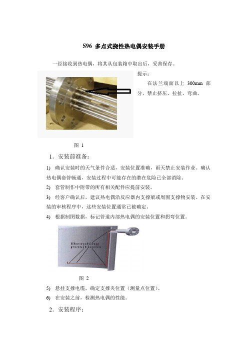
S96 多点式挠性热电偶安装手册一经接收到热电偶,将其从包装箱中取出后,妥善保存。
提示:在法兰端面以上300mm部分,禁止挤压、拉扯、弯曲。
图11.安装前准备:1)确认安装时的天气条件合适,安装位置准确,雨天禁止安装作业。
确认热电偶套管畅通,安装过程中可能存在的潜在危险已全部消除。
2)套管制作中附带的所有相关配件应提前安装。
3)经客户确认后,建议热电偶沿反应器内支撑梁或周围支撑物安装。
在安装的审核程序中,这些安装位置通常已被确定。
4)根据制图数据,标记管道内部热电偶的安装位置和拐弯位置。
图25)悬挂支撑电缆,确定支撑夹位置(测量点位置)。
6)在安装之前,检测热电偶的性能。
2.安装程序:1)在S96型热电偶安入反应器前,必须将其整顺。
2)在装入的热电偶上标记每一个拐点的位置。
3)标记完后,将多点式热电偶置于管嘴前。
图3:不要让四个支撑接触热电偶。
4)开始安装多点式热电偶。
将图2整个装置装入套管中,在装之前不要忘了提前将两个法兰之间的垫片装上。
5)法兰正确安装后紧固。
6)在反应器内部,热电偶的每一次弯曲标记都要很明显。
(热电偶的最小弯曲半径: 100 mm.)。
同上,将所有热电偶安到各自的位置。
7)将热电偶的顶部固定好后,其他的按照同样的过程安装(参照安装图及安装计划)。
8)一旦所有的热电偶全部装上后,应即可将它们通过支撑夹固定住(参照安装图)。
9)安装完毕后,再次检查热电偶的性能。
所有的脚手架,要求的设备及全体人员必须在安装之前到达安装指定位置,这样以来可减少不必要的等候和委托人的费用。
Yorkshire 加热系统 部件安装说明书
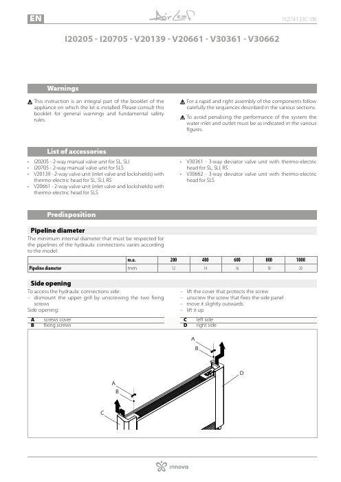
I 20205 - I20705 - V20139 - V20661 - V30361 - V30662W arningsT his instruction is an integral part of the booklet of theappliance on which the kit is installed. Please consult this booklet for general warnings and fundamental safety rules.For a rapid and right assembly of the components follow carefully the sequences described in the various sections.To avoid penalising the performance of the system the water inlet and outlet must be as indicated in the various figures.L ist of accessories• I20205 - 2-way manual valve unit for SL, SLI • I20705 - 2-way manual valve unit for SLS• V20139 - 2-way valve unit (inlet valve and lockshields) with thermo-electric head for SL, SLI, RS• V20661 - 2-way valve unit (inlet valve and lockshields) with thermo-electric head for SLS• V30361 - 3-way deviator valve unit with thermo-electric head for SL, SLI, RS• V30662 - 3-way deviator valve unit with thermo-electric head for SLSP redispositionP ipeline diameterThe minimum internal diameter that must be respected for the pipelines of the hydraulic connections varies accordingS ide openingTo access the hydraulic connections side:– dismount the upper grill by unscrewing the two fixing screws Side opening:– lift the cover that protects the screw– unscrew the screw that fixes the side panel – move it slightly outwards – lift it up2-way valve kit2-Way manual valve kit (I20205 - I20705)2-Way manual valve kit (I20205) is composed by:• 1 manual closing valve • 1 lockshield valve, fitted with micrometric adjustment, ca-pable of balancing the system load losses2-Way manual valve kit (I20705) is composed by:• 1 manual closing valve • 1 lockshield valve, fitted with micrometric adjustment, ca-pable of balancing the system load losses• 2 90° curved unionsAvailable on request: kit AI0204 of insulators to be mount-ed on the valve and on the lockshield in the case of a sys-tem supplied with cold water.2-Way valve unit kit with thermo-electric head (V20139 - V20661)2-Way valve unit kit with thermo-electric head (V20139) iscomposed by:• 1 automatic valve with thermo-electric head• 1 lockshield, fitted with micrometric adjustment, capable of balancing the system load losses The kit contains the insulation to be mounted on the valve and on the lockshield.2-Way valve unit kit with thermo-electric head (V20661) is composed by:• 1 automatic valve with thermo-electric head• 1 lockshield, fitted with micrometric adjustment, capable of balancing the system load losses• 2 90° curved unionsThe kit contains the insulation to be mounted on the valve and on the lockshield.D iagram of load lossesBelow is the diagram of load losses of 2-way valve in com-pletely open position, present in kit I20205, I20705, V20139, V20661.3-way valve kit3-Way deviator valve kit with thermo-electric head (V30361 - V30662)3-Way deviator valve kit with thermo-electric head (V30361) is composed by:• 1 automatic 3-way diverter valve with thermo-electric head• 1 lockshield valve, fitted with micrometric adjustment, ca-pable of balancing the system load losses The kit contains the insulation to be mounted on the valveand on the lockshield.3-Way deviator valve kit with thermo-electric head (V30662) is composed by:• 1 automatic 3-way diverter valve with thermo-electric head• 1 lockshield valve, fitted with micrometric adjustment, ca-pable of balancing the system load losses The kit contains the insulation to be mounted on the valve and on the lockshield.D iagram of load lossesBelow is the diagram of load losses of deviator valve in com-pletely open position, present in kit V30361, V30662.Below is the diagram of load losses of deviator valve in com-pletely closed position, present in kit V30361, V30662.C omponentsM ounting manual valveTo mount the manual valve:– turn the upper part of the handwheel, keeping the lower locknut blocked– bring it into a completely open position – screw the upper part of the handwheel until it is fixed on the valve bodyAt this point, the handwheel performs the adjustment.M ounting the thermostatic headTo mount the thermostatic head:– tighten the head to the valve bodyTo facilitate the system mounting, filling and venting opera-tions, even without electric power, the thermostatic head is supplied with a tool that keep it open.Remove the tool from the thermostatic head before start-ing the system.Now the pre-adjustment has been set and will not change if there are repeated openings or closings with the Allen key.D iagram of load lossesBelow is the diagram of load losses based on the adjustment of the lockshield valve present in all kits.C onnectionsThe choice and sizing of the hydraulic lines must be made by an expert who must operate according to the rules of good technique and the laws in force.To make the connections:– hydraulic lines positioning– use the "wrench against wrench" method– tighten the connections – check for leaks– coat the connections with insulating materialThe hydraulic lines and fittings must be thermally insulat-ed.Avoid partial insulation of the pipes.Avoid over-tightening the pipes to avoid damage to the insulation.Carefully check that the insulation is tight, in order to pre-vent the making and dripping of condensate.M ounting2-way valve (I20205) for SL and SLI versionsThe kit consist of:• 1 manual closing valve• 1 lockshield valve, fitted with micrometric adjustment, ca-pable of balancing the system load lossesAvailable on request: kit AI0204 of insulators to be mounted on the valve and on the lockshield in the case of a system supplied with cold water.Per montare il kit:– remove the side panel– access the hydraulic connection side – assemble the componentsF loor mounted version - with optional 3/4” EK stub pipe (code AI0501)W all mounted version - with optional 90° curved union (code AI0203)2-Way valve (I20705) for SLS versionThe kit consist of:• 1 manual closing valve• 1 lockshield valve, fitted with micrometric adjustment, ca-pable of balancing the system load losses• 2 90° curved unions Available on request: kit AI0204 of insulators to be mounted on the valve and on the lockshield in the case of a system supplied with cold water.Per montare il kit:– remove the side panel– access the hydraulic connection side– assemble the componentsF loor mounted versionW all mounted versionW all mounted version - with optional 90° curved union "L" (code AI0203)W all mounted versionW all mounted version - with optional 3/4" EK stub pipe (code AI0501)3-way deviator valve (V30662) for SLS versionW all mounted version。
热电偶说明书
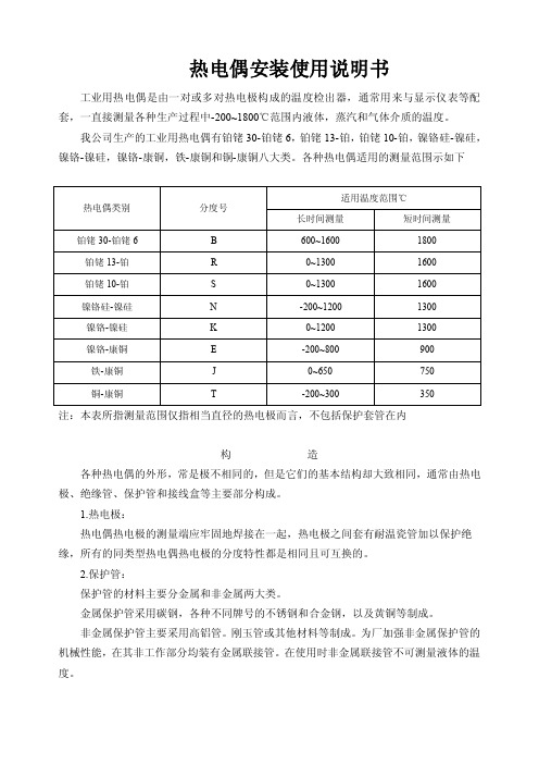
热电偶安装使用说明书工业用热电偶是由一对或多对热电极构成的温度检出器,通常用来与显示仪表等配套,一直接测量各种生产过程中-200~1800℃范围内液体,蒸汽和气体介质的温度。
我公司生产的工业用热电偶有铂铑30-铂铑6,铂铑13-铂,铂铑10-铂,镍铬硅-镍硅,镍铬-镍硅,镍铬-康铜,铁-康铜和铜-康铜八大类。
各种热电偶适用的测量范围示如下注:本表所指测量范围仅指相当直径的热电极而言,不包括保护套管在内构造各种热电偶的外形,常是极不相同的,但是它们的基本结构却大致相同,通常由热电极、绝缘管、保护管和接线盒等主要部分构成。
1.热电极:热电偶热电极的测量端应牢固地焊接在一起,热电极之间套有耐温瓷管加以保护绝缘,所有的同类型热电偶热电极的分度特性都是相同且可互换的。
2.保护管:保护管的材料主要分金属和非金属两大类。
金属保护管采用碳钢,各种不同牌号的不锈钢和合金钢,以及黄铜等制成。
非金属保护管主要采用高铝管。
刚玉管或其他材料等制成。
为厂加强非金属保护管的机械性能,在其非工作部分均装有金属联接管。
在使用时非金属联接管不可测量液体的温度。
3.接线盒:热电偶接线盒系供连接热电偶参比端与显示仪表之用。
接线盒一般用铝合金制成并分防溅式,防水式及插接式等结构形式。
4.安装固定装置:热电偶的安装固定装置供用户安装固定之用。
它分无固定装置、固定螺纹活动法兰、固定法兰、卡套螺纹、卡套法兰等形式。
技术特性1.热电偶的允差如下表中所示:(参与端处于0℃)℃注:t为被测温度(℃),在同一栏给出的两种允差值中,取绝对值较大者。
在-40℃以上的温度范围符合Ⅰ、Ⅱ级允差的T、E、K、N型热电偶,又要求在-40℃以下符合Ⅲ级允差时,由供需双方商定。
2.热响应时间:在温度出现阶跃变化时热电偶的输出变化至相当于该阶跃变化的50%所需的时间。
通常以t0.50表示。
参比端温度补偿热电偶的热电动势与温度关系所制定的分度表,是在参比端为0℃时分度的。
中英文电气安装说明和图例

中英文电气安装说明和图例LUMINAIRE 灯具1x28W T5 Batten Surface/Wall Mount fluorescent fitting1x28W T5 条形表面安装/壁装荧光灯2x28W T5 Batten Surface/Wall Mount fluorescent fitting2x28W T5 条形表面安装/壁装荧光灯1x28W T5(IP65) fluorescent fitting1x28W T5 (IP65) 荧光灯2x28W T5(IP65) fluorescent fitting2x28W T5 (IP65) 荧光灯1x14W Batten Surface/wall mount fluorescent fitting1x14W 条形表面安装/壁装荧光灯2x28W recessed/suspended mount luminaire fitting2x28W 嵌入式/悬挂式灯具1x240W metal halide fitting1x240W 金属卤化灯具1x18W (IP65) surface mounted luminaire1x18W(IP65) 表面安装的照明灯具1x26W Rectangular wall recessed luminaire1x26W 方形墙面嵌入式照明灯具2x28W Fluorescent fitting C/W prismatic diffuser2x28W 荧光灯,包括棱镜式散光罩1x26W PLC recessed down-light1x26W PLC 嵌入式筒灯2x26W PLC recessed down-light2x26W PLC 嵌入式筒灯2x18W PLC recessed down-light2x18WPLC 嵌入式筒灯11W recessed/suspended mount down-light11W 嵌入式/悬挂式筒灯1x150W high bay light1x150W 高顶灯2x55W weatherproof (IP54) aircraft obstruction light2x55W 防雨(IP54)航空障碍灯A-denotes fitting connected to battery pack (type as above)A指示灯,同电池组相连接(类型同上)Single sided exit light (Type E1)单侧出口灯(类型E1)Similar to Type E1 but with an additional arrow pointing to the right (Type E2)同类型E1相似,但是多一个向右的指示箭头(类型E2)Similar to Type E1 but with an additional arrow pointing to the left (Type E3)同类型E1相似,但是多一个向左的指示箭头(类型E3)Double faced exit light with an additional arrow on each face pointing to the left/right as appropriate (Type E4)双面出口灯,每面多一个指示箭头,指示左或者右(视情况而定)(类型E4)Similar to Type E1 but with an additional arrow pointing to the opposite directions (Type E5) 同类型E1相似,但是多一个指示箭头,指示相反的方向(类型E5)Switches开关LTG SW., 1 Gang One-way(Lighting)照明开关,1组单向LTG SW., One-way (2S denotes 2 Gang)照明开关,单向(2S表示2组)LTG SW., Two-way照明开关,双向LTG SW., Two-way (2S denotes 2 Gang)照明开关,双向(2S表示2组)Intermediate LTG SW., 1Gang中间照明开关,1组Intermediate LTG SW (2S denotes 2 Gang)中间照明开关(2S表示2组)Weatherproof LTG SW防雨照明开关Flameproof LTG SW防火照明开关DP LTG SW., 1Gang One-way双杆照明开关(Double Pole),1组单向Intermediate LTG SW (2S denotes 2Gang)中间照明开关(2S表示2组)Weatherproof LTG SW防雨照明开关Splash-proof LTG SW防溅式照明开关DP LTG SW., 1 Gang One-way双杆照明开关,1组单向Lighting switch panel照明开关柜Denotes switches of metal-clad type金属壳开关(铠装)Dimmer C/W switch调光器,包括开关Dimmer rack调光柜Dimmer switch panel (Digital type)调光器开关柜(数字型)20A DP switch C/W neon indication lamp and marked “water heater”20安培双杆开关,包括氖管指示灯,并标示“热水器”20A DP switch C/W neon indication lamp and marked “washing machine”20安培双杆开关,包括氖管指示灯,并标示“洗衣机”Bell push switch marked with Bell symbol铃按钮开关,并标记有“铃”符号Door chime point门铃Buzzer point蜂铃ElectricalAir/oil/vacuum circuit breaker (Rating and No. of poles as shown)空气、油压、真空断路器Moulded case/miniature circuit breaker (Rating and No. of poles as shown)断路器模块、小型断路器(跳菲)Residual current circuit breaker (RCCB) Rating and No. of poles as shown漏电断路器、漏电保护器DB/MB/MP/SSB/ESSB/LSB/LDB配电盘、量表板、计量盘、分配电板、电梯配电盘MSB/EMSB/GCP/PCP主配电柜、发电机控制箱、泵控制箱Subsidiary control panel辅助控制柜Tenant’s metering panel C/W MCBs subsidiary control panel and isolating SW. to powergrid’s approval租户计量盘,包括微型断路器二级控制箱和隔离开关(获得电网批准)Over-ground distribution box地上配电箱Isolation SW (Rating as shown)隔离开关Fuse switch (Rating as shown)熔丝开关、保险丝开关Switch-fuse (Rating as shown)开关熔断器、开关保险丝Fireman’s switch消防开关Junction box接线箱Cable end C/W termination kit电缆端头,包括端子箱Ammeter安培表V oltmeter电压表Power factor meter功率因数表Frequency meter频率计Kilowatt meter电力计、千瓦计Kilowatt-hour meter电表Maximum demand meter with alarm最大需量计,带警报Hour run meter运行小时计Energy monitoring device comprising current transformers, transducers, etc. For remote reading/logging of kilowatt-hour consumption能量监测装置,包括电流变压器、变送器等,用于远程读取、记录电能损耗Overcurrent/earth fault protection relay with instantaneous high set element (IDMTL characteristic unless otherwise indicated)过电流、接地故障保护继电器。
- 1、下载文档前请自行甄别文档内容的完整性,平台不提供额外的编辑、内容补充、找答案等附加服务。
- 2、"仅部分预览"的文档,不可在线预览部分如存在完整性等问题,可反馈申请退款(可完整预览的文档不适用该条件!)。
- 3、如文档侵犯您的权益,请联系客服反馈,我们会尽快为您处理(人工客服工作时间:9:00-18:30)。
WR系列热电偶WR Series ThermocoupleWZ系列热电阻WR Series Thermocouple使用安装手册Installation & Operation Manual安徽天康(集团)股份有限公司Anhui Tiankang (Group) Shares Co., Ltd目录Index1、概述General Description (1)2、工作原理Operation Theory (1)3、结构Configuration (2)4、主要技术参数Main Technical Parameters (3)5、安装及使用Installation & Operation (5)6、可能发生的故障及维修Possible Troubles & Maintenance (7)7、运输及储存Transportation & Storage (8)8、订货须知Notices in Ordering (8)9、型号命名Type Naming (9)1、概述General Description工业用热电偶作为温度测量和调节的传感器,通常与显示仪表等配套,以直接测量各种生产过程中-40~1600℃液体、蒸汽和气体介质以及固体表面温度;As sensor for temperature measuring and regulation, industrial-purpose thermocouple is usually connected with display meter and other meters to directly measure temperature of liquid, vapor, gas and solid surface ranging from -40℃to 1600℃.工业用热电阻作为温度测量和调节的传感器,通常与显示仪表等配套,以直接测量各种生产过程中-200~500℃液体、蒸汽和气体介质以及固体表面温度。
As sensor for temperature measuring and regulation, industrial-purpose thermal resistance is usually connected with display meter and other meters to directly measure temperature of liquid, vapor, gas and solid surface ranging from -200℃to 500℃.2、工作原理Operation Theory12.1热电偶工作原理Operation Theory of Thermocouple热电偶工作原理是基于两种不同成分的导体两端连接成回路,如两连接端温度不同,则在回路内产生热电流的物理现象。
热电偶由两根不同导线(热电极)A和B组成,它们的一端T1是互相焊接的,形成热电偶的测量端T1(也称工作端)。
将它插入待测温度的介质中;而热电偶的另一端T0(参比端或自由端)则与显示仪表相连,如果热电偶的测量端与参比端存在温度差,则显示仪表将指出热电偶产生的热电动势。
热电偶的热电动势随着测量端温度的升高而增大,它的大小只与热电偶的材料和热电偶两端的温度有关,而与热电级的长度、直径无关。
Thermocouple is based on physical phenomenon that two conductor of different materials is connected to form return circuit, when temperature on both contact is different, it results in thermoelectric potential in return circuit.2.2热电阻工作原理Operation Theory of Thermal Resistance热电阻是利用金属导体或半导体有温度变化时本身电阻也随着发生变化的特性来测量温度的,热电阻的受热部分(感温元件)是用细金属丝均匀地绕在绝缘材料作成的骨架上,当被测介质有温度梯度时,则所测得的温度是感温元件所在范围内介质层的平均温度。
制造热电阻的材料应具有以下特点:大的温度系数,大的电阻率,稳定的化学物理性能和良好的复现性等。
在现有的各种纯金属中,铂、铜和镍是制造热电阻的最合适的材料。
其中铂因具有易于提纯,在氧化性介质中具有高的稳定性以及良好的复现性等显著的优点,而成为制造热电阻的理想材料。
It is based on that temperature change of material results in change of its resistance. When resistance value changes, the working instrument will display relevant temperature.3、结构Configuration3.1感温元件直径及材料Diameter & Material of Thermal Elements3.1.1 热电偶Thermocouple3.2 接线盒Junction Box3.2.1接线盒供连接热电偶、热电阻参比端和显示仪表之用;Junction box is for connection between reference end of thermocouple and display instrument.3.2.2 接线盒防护等级IP65; Protection Class of Junction Box: IP653.2.3 防水接线盒结构图Structural Figure of Junction Box3.33.3.1 卡套螺纹接头 Threaded Head with Fastener卡套Fastener 扳手Spanner 固定卡套Fixed Fastener 可动卡套Movable Fastener3.3.2 Threaded Connector3.3.3 活动法兰式 Movable Flange4、 主要技术参数Main Technical Parameters 4.1 产品执行标准Executive StandardIEC1515 IEC751 GB/T16839-1997 JB/T8622-19974.2 测温范围及允差Measuring Range & Tolerance固定卡套可动卡套注:t为实际温度,允许可用温度度数表示,也可用实际温度的百分数表示,取其大者。
Notes: t is the actual temperature. It may be indicated with temperature centigrade or percentage of centigrade, the bigger one is preferred.4.2.2热电阻Thermal Resistance4.4常温绝缘电阻Insulation Resistance under Normal Temperature4.4.1热电偶Thermocouple热电偶在环境温度为20±15℃,相对湿度不大于80%,试验电压为500±50V(直流)电极与外套管之间的绝缘电阻≥100MΩ.m。
Insulation resistance between electrode and outer tube is no less than 100MΩ·m under condition that ambient temperature is 20±15℃, relative humidity is no more than 80%, and test voltage is 500±50V (D.C.).绝缘电阻用MΩ表示,即为常温绝缘与热电偶长度的乘积,对于长度小于1m的热电偶按1m计算。
The unit is MΩ·m,or product of insulation resistance and thermocouple length. Thermocouple with length less than 1m is considered as 1m. in calculation.4.4.2热电阻Thermal Resistance热电阻在环境温度为15~35℃,相对湿度不大80%,试验电压为10~100V(直流)电极与外套管之间的绝缘电阻≥100MΩInsulation resistance between electrode and outer tube is no less than 100MΩunder condition that ambient temperature is 15~35℃, relative humidity is no more than 80%, and test voltage is 10~100V (D.C.).4.5 热响应时间Thermal Response Time当温度出现阶跃变化时,仪表的电流输出信号变化至相当于该阶跃变化的50%所需的时间,通常以τ0.5表示When step change of temperature happens, τ0.5 is used to indicate the time for current output signal of instrument changes into 50% of the step change value.4.6 公称压力Nominal Pressure一般是指室温下保护管所能承受的静态外压力而不破裂,试验压力取公称压力的1.5倍。
允许工作压力不仅与保护管材料、直径、壁厚有关,还与其结构形式、安装方法、插入深度以及被测介质的温度、流速和种类有关。
It generally refers to the sustainable static pressure from outside on protection tube without breakage. It concern not only material, diameter & wall thickness of protection tube, but the structure, mounting way, insert length, flow speed and category of tested media as well.5、安装及使用Installation & Operation5.1 环境条件Ambient Conditionsa.环境温度:-25~80℃Ambient Temperature:b.相对湿度:5﹪~95%Relative Humidityc.机械振动: f≤55Hz,振幅<0.15mm Mechanical Shock: f≤55Hz,d.周围空气中不含有引起热电偶、热电阻腐蚀的介质There shall be no corrosive medium on components in ambient air.5.2 应避免在炉门或加热物体过紧之处安装,接线盒不可碰触被测介质的容器壁。