RPLIDAR A3开发套装使用手册
台达ASDA-A3系列伺服系统应用技术手册

序言
感谢您使用本产品, 本使用手册提供 ASDA-A3 系列伺服驱动器(简称 A3)及 ECM-A3 系列伺服电机相 关信息。 本手册内容
伺服驱动器和伺服电机的安装与检查 伺服架构及相关配线图 试运转操作的步骤 伺服调机教学 参数说明 通讯协议说明 异警排除 检测与保养
意指可能潜藏危险,若未遵守可能会对人员造成严重或致命的伤害。 意指可能潜藏危险,若未遵守可能会对人员造成中度的伤害,或导致产品严重损坏,或甚 至故障。 意指绝对禁止的行动,若未遵守可能会导致产品损坏,或甚至故障而无法使用。
接收检验
请照指定方式搭配使用 A3 驱动器及伺服电机,否则可能导致火灾或设备故障。
ASDA-A3 产品特色 台达开发的新一代控制算法,可以让用户简易克服机构上刚性不足或挠性结构的问题。新 的自动调机则可供无控制理论背景的操作人员,轻松完成调机。此外,使用者也可利用便 利的增益调整功能,提高驱动器的性能。而面宽薄型化的设计,可以节省机柜内部的空间。 新一代的 ECM-A3 的短小电机设计,更可满足设备结构小型化与轻量化的需求。 如何使用本操作手册 您可视本手册为学习使用伺服驱动器的参考信息,手册将告诉您如何安装、设定、使用及 维护本产品。在开始调机或设定前,请先阅读一到五章节。 本手册提供目录及主题式索引,若您无法在章节目录中找到需要的信息,亦可通过主题式 索引快速搜寻信息。 台达电子技术服务 如果您在使用上仍有问题,欢迎洽询经销商或本公司客服中心。
台达 ASDA-A3 系列伺服系统应用技术手冊
台 达电子 工 业股份有限 公司
机电事业群
33068 桃园市桃园区兴隆路 18 号 TEL: 886-3-3626301 FAX: 886-3-3716301
RPLIDAR 低成本360度2D激光雷达系统开发套装使用手册说明书
RPLIDARLow Cost 360 degree 2D Laser Scanner (LIDAR) SystemDevelopment Kit User Manual2014-2Rev.1Contents:1.OVERVIEW (2)I TEMS IN D EVELOPMENT K IT (2)RPLIDAR (2)USB A DAPTER (3)2.CONNECTION AND USAGE (4)C ONNECTION (4)I NST ALL D RIVER FOR THE USB A DAPTER (5)R UN D EMO A PPLICATION (6)T ROUBLE SHOOTING (8)3.DEVELOPMENT GUIDE AND SDK INTRODUCTION (9)P IN D EFINITION FOR RPLIDAR (9)P IN D EFINITION FOR USB A DAPTER (10)C ONFIGURE RPLIDAR S CAN F REQUENCY (10)SDK U SAGE (11)4.OPERATION RECOMMENDATION (12)P RE-H EATING FOR BEST PERFORMANCE (12)A MBIENT T EMPERATURE (12)A MBIENT L IGHT (12)5.REVISION HISTORY (13)1. OverviewThank you for purchasing RPLIDAR development kit. By using this kit, customers can easilyevaluating RPLIDAR’s performance. RoboPeak also provides SDK code to help customers integrate RPLIDAR to their system.Items in Development KitRPLIDAR Development Kit contains :● RPLIDAR (PWM motor driver embedded )● USB Adapter● RPLIDAR communication cable ● Micro-USB cableRPLIDARUSB AdapterMicro-USB cableRPLIDARRPLIDAR communication cableRPLIDAR development kit contains standard RPLIDAR unit (A1M1-R1). The RPLIDAR embedded logic IO drivable (3.3V) motor controller which can be used to configure scan frequency by tuning motor speed. Developer also can choose to turn off motor for power saving purpose.RPLIDAR usage and interface definition will be introduced in the coming sections. USB AdapterRPLIDAR development kit contains a USB adapter to provide power supply for RPLIDAR and convert RPLIDAR internal UART serial interface to USB interface.2. Connection and UsageConnectionRPLIDAR can be easily connect to PC by following bellow steps.1) Connect RPLIDAR with the USB adapter using provided communication cable.Thesocket is in the bottom of RPLIDAR.2)Connect the USB adapter to your PC using the Micro-USB cableAfter connecting RPLIDAR to your PC through the USB cable, the LED in the bottom of the RPLIDAR will light up and RPLIDAR start scanning.Install Driver for the USB AdapterThe USB adapter converts UART to USB using CP2102 chip. You need to install the device driver for the chip. The driver can be found in the provided SDK package or download from Silicon Labs’s official website:/products/interface/usbtouart/Pages/usb-to-uart-bridge.aspx Here’s the installation steps in Windows:After connecting the RPLIDAR with PC, find the driver file “CP210x VCP Windows” and choose correct operating system version accordingly: x86 for 32-bit OS and x64 for 64-bit OS.After Installing the driver according to installation steps, you should see corresponding serial port name in the [Control Panel] -> [Device and Printers]. Please refer to the bellow figure.in If the connection is ok, you shall see the UI like this:The firmware/hardware version and serial number of the RPLIDAR will show in the title line of the GUI. The supported commands of RPLIDAR are showed in the tool bar. The descriptions are listed in the bellow table.Button Function DescriptionStart Scan Scan data will be displayed after scan core startingworkStop Scan Scan core enter power save modeSave Scan Data Save current scan data to the local fileRestart RPLIDAR Restart scan core to clear internal errorsPress the Start Scan button,the scan data will be displayed in the UI:Use the mouse wheel to zoom in and out. Move the cursor to any sample point, the distance and degree value to the RPLIDAR will be showed in the screen with red font. The scan frequency also showed in the UI.T rouble shootingWhen scan core or laser power works abnormally, scan core will enter protection mode. This state can be retrieved using SDK API. If such scenario happened, sending restartcommand can let scan core reset.3. Development Guide and SDK IntroductionPin Definition for RPLIDARThe socket in the bottom of RPLIDAR is using 5267-7A specification: 2.5mm spacing 7 pin.Any communication cable has 5264-7 terminal block can be used to connect with RPLIDAR. Please find the detail pin definition in the bellow table:PinSignal name Type DescriptionMinimum TypicalMaximum P1 VMOTO Power Power supply for the RPLIDAR scan motor- 5V 9V P2MOTOCTLInputEnable pin for RPLIDAR scan motor/PWM control signal (active high)0V-VMOTOP3 GND Power GND signal for RPLIDAR scan motor - 0V - P4 V5.0 Power Power supply for RPLIDAR scan core 3.6V 5V 6V P5 TX Output Serial output for RPLIDAR scan core 0V - 5V P6 RX Input Serial input for RPLIDAR scan core 0V - 5V P7 GND PowerGND signal for RPLIDAR scan core- 0V V5.0External system must provide required VMOTO and V5.0 power to make scan motor and scan core work correctly. In most of scenarios, VMOTO and V5.0 can share the same power supply.MOTOCTL Pin used to control scan motor speed to adjust RPLIDAR’s scan frequency , PWM signal also can be applied. The equivalent circuit showed as bellow:You can also refer to the bellow Reference Design for RPLIDAR development.P1P7…5267-7ADescription Since USB adapter ’s contr ol signal MOTOCTL is fixed to high level, RP LIDAR’s scan motor is always rotating at its highest speed which makes RPLIDAR working on a relative high scan frequency. You can configure RPLIDAR’s scan freque ncy by controlling motor speed.By connecting MOTOCTL signal to the device has PWM output function such as MCU’s PWM output I/O port, RPLIDAR’s scan frequency can be locked in a proper value by adjust duty ratio of PWM using the scan frequency feedback provided by RPLIDAR core.VMOTO GND V5.0 GND TX RXMOTOCTLPower (4-9V DC)Power (5V DC)UART PWM Generator MCU/DSPRPLIDAR P1P7…5267-7APlease refer to RPLIDAR protocol and application note for more information. SDK also contains the sample code.SDK UsageRoboPeak provides RPLIDAR SDK support both Windows and Linux platform. The SDK contains sample code. Please refer to SDK document for more information.4.Operation RecommendationPre-Heating for best performanceThe scan core will heating when start working. We recommended pre-heating RPLIDAR (Start scan mode, the scan motor is rotating) for more than 2 minutes to get the best measurement accuracy.Ambient T emperatureRPLIDAR’s measurement resolution is sensitive to t he ambient temperature. Improper use may even damage the sensor. Please avoid using RPLIDAR in extreme high temperature (>40 degree) and too low temperature (<-10 degree).Ambient LightAlthough RPLIDAR is not sensitive to ambient light, improper use may still lead to errors.In indoor environment, please avoid lighting RPLIDAR with strong light source such as high-power laser.In outdoor environment, please avoid facing RPLIDAR directly into sun light. This may leads to permanent damage to the image sensor of RPLIDAR.The standard version of RPLIDAR may have less measurement range in strong sun light environment. Please contact RoboPeak for any customization options.5.Revision History。
火乐 HOLATEK A3

在购入国使用本机器时,请使用其附带的电源线;在其他国家使用本 机器时,必须购置并使用适合该国家电源要求的电源线,同时必须留 意该国家的安全标准 ● 水及异物
5 / 36
「
智
能
投
影
机
用
户
手
册
」
切勿在机器上放置花瓶或任何盛有水或其它液体的容器,切勿让水或 其它液体溅在机器上,否则有引起火灾及触电的危险 异物(金属等)混入机器有造成火灾及触电的危险,应立即执行下述操 作: 1. 2. 3. 关闭机器的电源; 拔下机器的电源插头; 与您的经销商或火乐特约服务中心联络
此标志表示,若无视此标志、错误操作,有导致人员死亡或严重 警告 受伤之潜在危险
此标志表示,若无视此标志、错误操作,有导致人员死亡或严重 注意 受伤之潜在危险
使用须知
警告
● 冒烟、异味、烫热及其他异常 发现有冒烟、异味或任何其他异常情况时,请立即停止使用机器(继续 使用有造成火灾及触电的危险) ,并请立即采取以下措施: 1. 2. 3. 关闭机器的电源; 拔下机器的电源插头; 与您的经销商或火乐特约服务中心联络
4 / 36
「
智
能
投
影
机
用
户
手
册
」
● 故障 在操作正确的情况下,若画面显示异常或出现任何其他的异常现象, 请立即停止使用机器(继续使用有造成火灾及触电的危险) ,并请立即 采取以下措施: 1. 2. 3. 关闭机器的电源; 拔下机器的电源插头; 与您的经销商或火乐特约服务中心联络
● 电源线 电源线使用不当有造成火灾及触电的危险,必须遵守以下注意事项: 必须使用输出电压与机器的额定电压一致的交流电源; 不可在电源插座上插入过多的装置使其超载
SLAMTEC思岚科技RPLIDAR 360度激光扫描测距雷达通讯接口协议与应用手册
等待应答数据
下一个请求…
图表 2-1 RPLIDAR 单次请求-应答通讯模式
外部系统应避免在该通讯模式中,RPLIDAR 还未对前一次请求做出应答前再次 发送请求。否则第二次的请求数据可能将被 RPLIDAR 丢弃。
1. RPLIDAR 通讯接口简介
外部系统通过 TTL 电平的 UART 串口信号与 RPLIDAR 测距核心进行通讯。通 过本文档定义的通讯协议,外部系统可以实时获取 RPLIDAR 的扫描数据、设备 信息、设备健康状态。并且通过相关命令调整 RPLIDAR 的工作模式。
TX
RX
外部系统
GND
图表 1-1 RPLIDAR 与外部系统通讯示意图
按照不同的请求类型,RPLIDAR 具有三种不同的请求/应答模式:
1. 标准的单次请求-单次应答模式
该模式用于外部系统向 RPLIDAR 获取相关信息的通讯中。RPLIDAR 在收到这 类请求后,将在必要的操作后通过单个应答包发送外部系统需要的数据。
RPLIDAR
外部系统
执行操作
发送请求报文 发送应答报文
SDK 与示例程序 ............................................................................................................................................... 3 2. 基本通讯协议 ......................................................................................................................................... 4
A33_lichee使用手册

A33lichee 使用手册 Co n f i d e n t i a l文档履历版本号日期制/修订人制/修订记录V1.02014-06-10初始版本C o n f i d en t i al目录A33 (1)1. 简介 (4)2. 目录结构 (4)2.1. brandy (4)2.2. buildroot (5)2.3. linux-3.4 (5)2.4. tools (6)3. 编译系统 (7)3.1. 使用说明 (7)3.2. 二次开发 (7)3.2.1. 指定配置文件 (7)3.2.2. 添加系统平台 (7)3.2.3. 打包脚本说明 (8)4. Lichee 定制 (8)4.1. 根文件系统定制 (8)4.2. 集成软件包 (9)4.2.1. 源代码包 (9)4.2.2. 二进制包 (11)4.2.3. 可执行文件 (12)5. 固件定制 (12)5.1. 分区属性 (12)5.2. 规划分区 (13)6. Declaration ............................................................................................................................................ 14 C o n f i d e n t i a l1. 简介本文档用于介绍A33芯片的Linux BSP 的目录结构,固件定制和Lichee 定制。
2. 目录结构 ├── brandy├── buildroot├── build.sh├── linux-3.4├── README└── tools2.1.brandy 存放boot0和u-boot 源码,其目录结构为├── basic_loader├── build.sh├── extern-libs├── gcc-linaro├── pack├── pack_tools├── u-boot-2011.09└── u-boot-2013.01baisc_loader :boot0源码,编译器使用arm-cc ,搭配cygwin 。
audi a3 2015 service intervals说明书
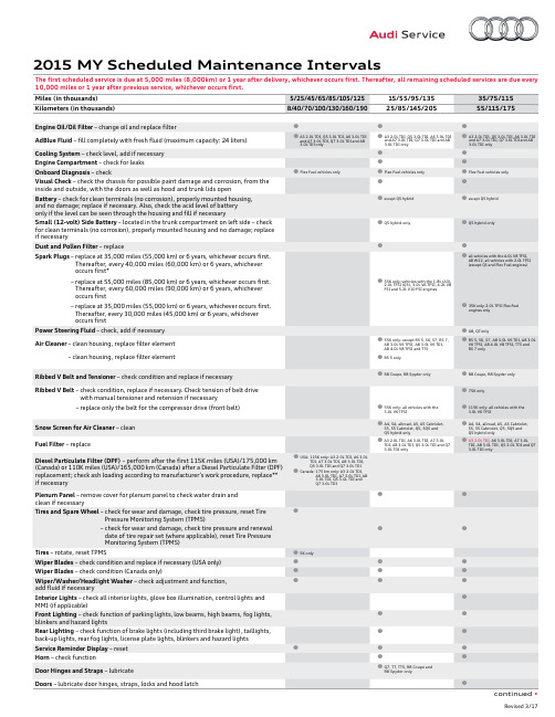
2015 MY Scheduled Maintenance IntervalsThe first scheduled service is due at 5,000 miles (8,000km) or 1 year after delivery, whichever occurs first. Thereafter, all remaining scheduled services are due every 10,000 miles or 1 year after previous service, whichever occurs first.2015 MY Scheduled Maintenance Intervals (continued)The first scheduled service is due at 5,000 miles (8,000km) or 1 year after delivery, whichever occurs first. Thereafter, all remaining scheduled services are due everyBrake Fluid – replace every 2 years regardless of mileageCloth Top – check function and rollover protection every 2 years regardless of mileage (A5/S5 Cabriolet and R8 Spyder only)AdBlue Fluid – replace every 4 years regardless of miles/kilometers only if AdBlue has not been filled within the last 4 years (Q7 3.0L TDI, A8 3.0L TDI, A6 3.0L TDI, A7 3.0L TDI and Q5 3.0L TDI only) Crash Active Headrest – check function every 2 years regardless of miles/kilometers (A8 only)BorgWarner Clutch – change oil every 3 years regardless of mileage/kilometers (A3, Q3, TT and TTS only)*Does not include 2.0L TFSI Flex Fuel engines.** I f DPF replacement is not necessary, perform check every 20,000 miles (30,000 km) thereafter until replacement becomes necessary. Subsequent DPF replacement interval is a minimum of 120,000 miles (195,000 km) thereafter.Audi of America, Inc. believes the information and specifications to be correct at the time of printing. Specifications, maintenance intervals, standard features and options subject to change without notice.。
好越达打菲软件说明书
软件说明书一、打菲软件工厂生产流程图解。
二、软件总体操作流程新增款号---新增定单-----新增裁单-----打菲、打印裁床单、打印车间收发日报表----入菲-----工介录入----工价执行------件工日报表。
-----月报表处理------查看月报表方面的报表。
三、新增款号第一步输入款号名(款号名由:数字,汉字,字母,下划线组成,最长不能超过20个字母,款号不能重复),第二步输入工序(工序的意思是做这个款的衣服的工序是什么)点插入就行了每点插入一次工序栏就多一道工序,一般的要比这个款的工序多留几个,比如说某个款衣服工序有十二道,那插入工序的时候可以插到十六道多留几个以便心以后要加工序,插入工序后点‘默认工序’默认工序的意思是按上到下从1依次排列下来。
如果不按这个顺序可以手工输入。
第三步输入工序名,工序名的意思是工序的名称,比如说梭边,车裤脚等。
第四步保存注释:‘从…复制’的意思是如果有旧款工序和要新建的款的工序是一样的就选择旧款进行复制,这样就节省了输入工序和工序名的时间。
四、新增定单这个介面是新增定单介面,第一步输入定单号(定单号的意思是下单的单号然后要选择款号,表示这个单订的是这个款)其实只要输入定单号和款号就可以保存了,其他的都可以不要输入,这个要按工厂的实际情况而定,如果需要输入的就选择性的输入。
定单明细是可以选择要不要输入的(定单明细的意思是:客户订单明细表)。
点系统管理里面的设置就会出现上面这个介面,这里不打勾新增定单就不会出现定单明细。
五、新增裁单点存盘打印后出现:点是:点否:汇总表就出现在下一页。
存盘不打印是保存退出的意思。
存盘打印,是保存然后打印出来。
裁单是裁床要裁衣服的明细表。
六、印菲点打印后,电脑桌面下的任务栏会出现印菲有两种方式,方式是打印某扎。
这种方式就是只打印某一床的指定扎号,比如说打印机在打印整床的时候碰到停电的情况,那么就没有必要已经打印的重打,只要把后面没有打印的打完就行了。
湛特C RPLIDAR A3 低成本360度激光距离扫描开发套件用户手册说明书
RPLIDAR A3 Low Cost 360 Degree Laser Range Scanner Development Kit User Manual Model:A3M12018-01-31rev.1.0CONTENTS (1)OVERVIEW (3)I TEMS IN THE D EVELOPMENT K IT (3)RPLIDAR A3 (4)USB A DAPTER (4)CONNECTION AND USAGE (5)C ONNECTION (5)I NSTALL D RIVER FOR THE USB A DAPTER (5)R UN D EMO A PPLICATION (7)T ROUBLESHOOTING (9)M OTOR S PEED A DJUSTMENT (9)SDK INTRODUCTION AND USAGE (11)RPLIDAR A3P IN D EFINITION AND S PECIFICATION (11)P IN D EFINITION FOR THE USB A DAPTER (12)C ONFIGURE RPLIDAR A3S CAN F REQUENCY (14)SDK U SAGE (14)OPERATION RECOMMENDATION (15)P RE-H EATING FOR B EST P ERFORMANCE (15)A MBIENT T EMPERATURE (15)A MBIENT L IGHT (15)REVISION HISTORY (16)APPENDIX (17)I MAGE AND T ABLE I NDEX (17)OverviewRPLIDAR A3 development kit includes the matched tools used for evaluating RPLIDAR’s performance and initial development. After connecting the RPLIDAR A3 with PC via USB cable and connecting the power adapter to the USB cable, users can observe the cloud map of the environment scanning point collected by the RPLIDAR in RoboStudio and start development based on the SDK.Items in the Development KitRPLIDAR Development Kit contains:o RPLIDAR(PWM motor driver embedded)o USB Adaptero Micro-USB cableo Power adapterRPLIDARPower AdapterUSB adapterMicro-USBcableFigure 1-1 Items in the RPLIDAR Development KitRPLIDAR A3Figure 1-2 The RPLIDARThe RPLIDAR A3 development kit contains standard RPLIDAR A3 unit (A3M1). The RPLIDAR is embedded with logic IO drivable motor controller which can be used to configure the scan frequency by tuning motor speed. Developers can also choose to turn off the motor for power saving purpose.RPLIDAR usage and interface definition will be introduced in the coming sections. USB AdapterThe USB adapter comes with a dial switch. It can be used to switch the Baud rate from 115200 to 256000 or vice versa, which is compatible with RPLIDAR A3 and former RPLIDAR series. Please note that the Baud rate should be set as 256000 if the USB adapter is connected with RPLIDAR A3..Figure 1-3 RPLIDAR AdapterConnection and UsageConnectionRPLIDAR A3 can be easily connected to PC according to the following steps.1)Connect RPLIDAR A3 with the USB adapter.Figure 2-1 Connect RPLIDAR A3 and USB Adapter2)Connect the USB adapter to your PC via the Micro-USB cable. If the PC ison, after connecting the USB cable to your PC and connecting the poweradapter to the USB cable, the indicator light of the USB will light up but theRPLIDAR will not start scanning.Figure 2-2 Connect the USB Adapter to PC via Micro-USB Cable Install Driver for the USB AdapterThe USB adapter converts UART to USB by using CP2102 chip. You need to install the device driver for the chip. The driver can be found in the provided SDK package or downloaded from Silicon Labs’ official website:/products/mcu/Pages/USBtoUARTBridgeVCPDrivers.aspxHere’s the installation steps in Windows: after connecting the RPLIDAR with PC, please find the driver file “CP210x VCP Windows” and choose correct operating system version accordingly: x86 for 32-bit OS and x64 for 64-bit OS.Figure 2-3 Choose USB Adapter Driver for InstallationFigure 2-4 Start Page of USB Adapter Driver InstallationAfter Installing the driver according to the above installation steps, you will see corresponding serial port name in the [Control Panel] -> [Device and Printers]. Please refer to the below figure.Figure 2-5 Recognized Serial Port Name Matched with the USB AdapterRun Demo ApplicationSLAMTEC provides a Lidars plugin in RoboStudio for users in test and evaluation. You can view the scan result directly in the UI and save the scan result to files for further processing.This GUI demo can only run under Windows. For Linux and MacOS users, please refer to the other simple demo provided in the SDK.Please make sure you have connected RPLIDAR to PC by using USB adapter and installed the device driver correctly before running the demo application in RoboStudio. Launch RoboStudio and log in.Figure 2-6 RoboStudio Login PageIf the connection is ok, you shall see the user interface is shown as below.1. Click File->Lidars to open the lidar control panel in the left;2. Click Serial Ports to extend the lidar lists and you’ll find the RPLIDAR A3 previously connected to your PC;3. Click the RPLIDAR A3 icon to extend the tool buttons below the icon: the left one is to adjust the motor speed while the right one is to open the tool bar in the major work area as shown in Figure 2-7.Figure 2-7 The Lidar Plugin in RoboStudioThe serial number, version and model of the RPLIDAR A3 will show next with its icon in the lidar control panel. The supported commands of RPLIDAR are showed in the tool bar. The descriptions are listed in the bellow table.ButtonFigure 2-8 The Supported Commands of RPLIDAR in RoboStudioPress the Start Scan button,the scan data will be displayed as below(by default, the motor rotating speed should be about 10Hz.):Figure 2-9 The Scan Outline by RPLIDAR in RoboStudioRight click in the major working area to choose a range so as to zoom in or out the view.The scan frequency is also showed in the above interface. TroubleshootingWhen the scan core or the laser power works abnormally, the scan core will enter protection mode. This state can be retrieved via SDK API. If such scenariohappened, please send restart command to reset the scan core.Motor Speed AdjustmentDuring the running process, different motor rotating speed can be achieved bypressing the button, which can fit in different working environments or meet specific requirements. There will be a speed adjustment dialog box and dash board popped up for users to enter required speed. After entering a value, the motor will work as the settled rotating speed automatically. User can also drag the sliding handle to the required rotating speed.The current actual rotating speed will show in the upper left corner of the major work area. For instance, the actual rotating speed in the following screenshot is 11.92Hz.Figure 2-10 The Motor Speed Adjustment Dialogue of RPLIDAR in RoboStudioRPLIDAR A3 Pin Definition and SpecificationRPLIDAR A3 is using XH2.54-5P specification plug. Please use it with socket that meet the specification of XH2.54-5P. The detailed pin definition is shown as below:Figure 3-1 RPLIDAR A3 PinsFigure 3-2 RPLIDAR Pin Definition and SpecificationRPLIDAR A3 uses the one 5V DC power supply for powering the scan motor and the scan core at the same time. No extra power is required.With build-in and speed-adjustable motor driver, RPLIDAR A3 can control the start, the stop and the rotating speed of the motor via the MOTOCTL signal. o Reference Design for RPLIDAR developmentSDK Introduction and UsageColor Signal name Type DescriptionMinimum Typical MaximumRed VCC Power Power supply for the wholeRPLIDAR4.9V5V 5.5V Yellow TX Output Serial output for RPLIDAR scan core0V 3.3V 3.5V Green RX Input Serial input for RPLIDAR scan core 0V 3.3V 3.5V Black GND Power GND0V 0V 0V BlueMOTOCTLInput (pull down)Enable pin for RPLIDAR scan motor/PWM control signal (active high)0V3.3V5VRedXH2.54-5PVCCTXRXGND MOTOCTLFigure 3-3 RPLIDAR A3 Pins Reference DesignPin Definition for the USB AdapterThe USB adapter is also using XH2.54-5P specification socket, and it can be connected with RPLIDAR A3 directly. The pin definition is the same as the RPLIDAR A3.Power adapter specificationInputFigure 3-4 RPLIDAR Power Adapter Input SpecificationItemUnitMinTypical Max CommentsInput voltage VAC 90 100-240 264 Single phase Input frequency Hz 47 50-60 63Input current A - - 0.4 When the input is 100Vac and in maximum loadInrush current (cold boot)A--30When the input is 230Vac and in maximum loadAverage efficiency - 78.7% - -When the input is 115/230Vac and outputting 100%/75%/50%/25% of the load, the average efficiency is lower than 78.7%.Input no-load powerconsumptionW- - 0.1When the input is 100Vac-240Vac, the input no-load power consumption is lower than 0.1W.V5.0 GND TX RXMOTOCTLPower(5V DC)UART PWM Generator MCU/DSPRPLIDAROutputFigure 3-5 RPLIDAR Power Adapter Output SpecificationRipple wave and noise: When testing the ripple and noise, choose20Mhz wideband when setting the oscilloscope, and the output end should have a 0.1uF ceramic capacitor and a 10uF electrolytic capacitor connected in parallel. (the input should be in 100Vac-240Vac).Line/load regulationFigure 3-6 RPLIDAR Power Adapter Line/Load RegulationTurn-on delay3s when the input is 100Vac and at maximum load.2s when the input is 240Vac and at maximum load.Holdup timeAt least 30ms when shut the input is between 240Vac/50Hz and at maximum load.Rise time40ms when the input is between 100Vac-240 Vac and at maximum load.Output overshoot/undershoot7% is a maximum when powering on or off.Output load transient responseWhen the voltage output is between 4.75V and 5.25V, the load will change from 25% at maximum to 50% then back to 25%, or from 50% at maximum to 75% then back to 50%. The slope is 0.5A/us. The frequency is 100Hz. Output overshoot is lower than ±5%.Protection requirementShort circuit protection: when outputting short circuit, the input power will lower and will not have any affect. After ending the short circuit, the system will recover automatically.Overcurrent protectionOCSET: within 110%-180% of maximum load (with rated voltage), when outputting overcurrent, the output will go to hiccup mode. After ending the overcurrent, the system will recover automatically.Configure RPLIDAR A3 Scan FrequencyThe motor speed control signal MOTOCTL can be configured directly via the USB adapter of RPLIDAR A3. Therefore, the RPLIDAR A3’s scan frequency can be modified by invoking the related functions in the SDK to configure the motor speed.Without the USB adapter, users can also control the speed by setting the PWM duty cycle of MOTOCTL. Please note that the PWM frequency is 20kHz. For more detailed parameter and index, please refer to the datasheet.Please refer to the RPLIDAR protocol and application note for more information and the SDK for the sample code on RPLIDAR scan frequency.SDK UsageSLAMTEC provides RPLIDAR SDK support on both Windows and Linux platform. And users can embed the SDK source code to other operational system or embedded system quickly. Please refer to the SDK document for more information.Pre-Heating for Best PerformanceThe scan core will be heating when start working. We recommend pre-heating RPLIDAR (Start the scan mode and the scan motor is rotating) for more than 2 minutes to get the best measurement accuracy.Ambient TemperatureRPLIDAR’s measurement resolution is sensitive to the ambient temperature. Improper use may even damage the sensor. Please avoid using RPLIDAR in extreme high temperature (>40 degree) and too low temperature (<-10 degree).Ambient LightCompared with RPLIDAR A2 series, RPLIDAR A3 performs better to resist ambient light interference, which supports it to work properly in outdoor environment.RPLIDAR A3 can work in two modes: enhanced mode and outdoor mode.Enhanced mode is designed for indoor environment. Typical indoor light (including situations without light) will not affect the performance of RPLIDAR. Strong light (such as high power laser) will harm the optical system of LIDAR, which should be avoided.During outdoor mode, RPLIDAR A3 can work normally to detect objects under direct ambient light. However, the ranging distance might be shorter under strong direct sunlight and it is still necessary to protect the optical system from direct sunlight.Image and Table IndexF IGURE 1-1I TEMS IN THE RPLIDAR D EVELOPMENT K IT (3)F IGURE 1-2T HE RPLIDAR (4)F IGURE 1-3RPLIDAR A DAPTER (4)F IGURE 2-1C ONNECT RPLIDAR A3 AND USB A DAPTER (5)F IGURE 2-2C ONNECT THE USB A DAPTER TO PC VIA M ICRO-USB C ABLE (5)F IGURE 2-3C HOOSE USB A DAPTER D RIVER FOR I NSTALLATION (6)F IGURE 2-4S TART P AGE OF USB A DAPTER D RIVER I NSTALLATION (6)F IGURE 2-5R ECOGNIZED S ERIAL P ORT N AME M ATCHED WITH THE USB A DAPTER (6)F IGURE 2-6R OBO S TUDIO L OGIN P AGE (7)F IGURE 2-7T HE L IDAR P LUGIN IN R OBO S TUDIO (8)F IGURE 2-8T HE S UPPORTED C OMMANDS OF RPLIDAR IN R OBO S TUDIO (8)F IGURE 2-9T HE S CAN O UTLINE BY RPLIDAR IN R OBO S TUDIO (9)F IGURE 2-10T HE M OTOR S PEED A DJUSTMENT D IALOGUE OF RPLIDAR IN R OBO S TUDIO (10)F IGURE 3-1RPLIDAR A3P INS (11)F IGURE 3-2RPLIDAR P IN D EFINITION AND S PECIFICATION (11)F IGURE 3-3RPLIDAR A3P INS R EFERENCE D ESIGN (12)F IGURE 3-4RPLIDAR P OWER A DAPTER I NPUT S PECIFICATION (12)F IGURE 3-5RPLIDAR P OWER A DAPTER O UTPUT S PECIFICATION (13)F IGURE 3-6RPLIDAR P OWER A DAPTER L INE/L OAD R EGULATION (13)。
YDlidar T-mini Pro 激光雷达开发套件用户手册说明书
Shenzhen EAI Technology Co.,Ltd. DOC#:01.13.005902 YDLDIAR T-MINI PRO USER MANUALCONTENTS1YDLIDAR T-MINI PRO LIDAR DEVELOPMENT KIT (1)1.1Development Kit (1)2OPERATION UNDER WINDOWS (1)2.1Device Connection (1)2.2Driver Installation (3)2.3How to Use LidarViewer (5)2.3.1Start Scanning (6)2.3.2Data Storage (6)2.3.3Display Mean and Standard Deviation (7)2.3.4Display Intensity Value (7)2.3.5Play and Record (8)2.3.6Debug (9)2.3.7Filter (9)3LINUX ROS OPERATION (10)3.1Device Connection (10)3.2Compile and Install YDLidar-SDK (10)3.3ROS Driver Installation (10)3.4Run the ydlidar_ros_driver (11)3.5RVIZ Scan Result Checking (11)3.6Modify Scan Angle (12)4REVISE (14)1YDLIDAR T-mini Pro LIDAR DEVELOPMENT KITThe development kit of YDLIDAR T-mini Pro lidar (hereinafter referred to as T-mini Pro) is an accessory tool provided for performance evaluation and early development of the T-mini Pro. Through the T-mini Pro development kit, and with the evaluation software, users can observe point cloud data scanned by T-mini Pro on your environment or development on the SDK.1.1Development KitThe T-mini Pro development kit has the following components:FIG 1YDLIDAR T-MINI PRO DEVELOPMENT KITCHART 1YDLIDAR T-MINI PRO LIDAR DEVELOPMENT KIT DESCRIPTION Item Qty. DescriptionT-mini Pro Lidar 1Standard version of the T-mini Pro Lidar, internal integrated motor drive, canrealize motor stall control and motor control USB Type-CCable1Use with USB adapter board to connect T-mini Pro and PC. USB cable isboth a power supply cable and a data cable USB AdapterBoard1Realize USB to UART, convenient for the rapid interconnection of T-miniPro lidar and PC. In addition, it provides Micro USB power interface (PWR)for auxiliary power supplyNote: USB Adapter board has two interface: USB_DATA、USB_PWR.USB_DATA: Data powered interface. In most cases, this interface can be used to meet power andcommunication requirements.USB_PWR: Auxiliary power supply interface. The USB interface of some development platformshas weak current drive capability. At this time, auxiliary power supply can be used.2OPERATION UNDER WINDOWS2.1Device ConnectionWhen T-mini Pro is evaluated and developed under windows, T-mini Pro and PC need to be interconnected. The specific process is as follows:T-mini Pro Lidar USB Type-C Cable USB Adapter BoardFIG 2YDLIDAR T-MINI PRO DEVICE CONNECTION STEP 1FIG 3YDLIDAR T-MINI PRO DEVICE CONNECTION STEP 2Connect the adapter board with T-mini Pro first, then connect the USB cable to the USB port of the adapter board and the PC. Note that the Type-C interface of the USB cable is connected to the USB_DATA of the USB interface board, and the idle mode is used after T-mini Pro is powered on. The motor does not rotate.The drive current of USB interface of some development platforms or PC is not sufficient. T-mini Pro need to be connected to the auxiliary power supply of +5V, otherwise the lidar will be abnormal.FIG 4YDLIDAR T-MINI PRO AUXILIARY POWER SUPPLY2.2Driver InstallationTo evaluate and develop the T-mini Pro under Windows, you need to install the serial port driver of the USB adapter board. The USB adapter board of this kit adopts CP2102 chip to realize serial port (UART) to USB signal conversion. Its driver can be downloaded from our official website or downloaded from the official website of Silicon Labs.https:///dowfile.html?id=97/products/development-tools/software/usb-to-uart-bridge-vcp-driversAfter unzipping the driver package, run the CP2102's Windows driver installation file (exe file under CP210x_VCP_Windows). Please select the 32-bit version (x86) or 64-bit version (x64) installation program according to the version of the windows operating system.FIG 5YDLIDAR T-MINI PRO DRIVER VERSION SELECTIONDouble-click the exe file and follow the prompts to install it.DevelopmentPlatform5V PowerSupplyFIG 6YDLIDAR T-MINI PRO DRIVER INSTALLINGAfter the installation is complete, you can right-click on [My Computer] and select [Properties]. On the open [System] screen, select [Device Manager] from the left menu to access the Device Manager.Expand [Port] to see the serial port name corresponding to the identified USB adapter, that is, the driver installation is successful. The following figure shows COM3. (Note that the port must be checked in case of T-mini Pro and PC interconnection).FIG 7YDLIDAR T-MINI PRO DRIVER INSTALLATION CHECK2.3How to Use LidarViewerYDLIDAR provides LidarViewer, a point cloud data visualization software for T-mini Pro real-time scanning. Users can use this software to visually observe the T-mini Pro scanning map: YDLIDAR provides T-mini Pro real-time point cloud data and real-time scanning frequency. At the same time, the scanned data can be saved offline to an external file for further analysis. Visualization software download link: https:///Public/upload/download/TOOL.zipBefore using the YDLIDAR software, make sure that the T-mini Pro USB adapter board serial port driver is installed successfully, and interconnect the T-mini Pro with the USB port of the PC. Run the evaluation software: LidarViewer.exe, select the corresponding serial port number and model number. Meanwhile, users could choose language on the top right corner.FIG 8YDLIDAR T-MINI PRO EVALUATION SOFTWAREIf there is no T-mini Pro model, please refer to the following to add T-mini Pro model.FIG 9YDLIDAR T-MINI PRO PARAMETER CONFIGURATIONIf the connection is correct, you will see the following screen:FIG 10POINTCLOUD VIEWER INTERFACE2.3.1 Start ScanningClick to start scanning and display the environment point cloud. Click to stop it. asshown below:FIG 11LIDAR SCANNING POINT CLOUD DISPLAY2.3.2 Data StorageDuring lidar scanning, click [File] in the main menu, select [Export to Excel], and save pointcloud data according to the prompts. Then the system will save the point cloud information scannedin a circle in Excel format.FIG 12SAVE DATA2.3.3 Display Mean and Standard DeviationClick [Tools] in the main menu, then select [Mean And STD] - [View].FIG 13YDLIDAR T-MINI PRO DISPLAY MEAN AND STANDARD DEVIATIONChoose one according to your needs, move the mouse to the test position, right-click the pop-up menu, and select [Lock Mouse Tracking].FIG 14LOCK MOUSE TRACKING2.3.4 Display Intensity ValueClick [Data] in the main menu and select [Intensity Histogram].FIG 15DISPLAY INTENSITY VALUEThe main window is displayed as follows, showing the intensity values of a total of 100 points on the left and right of the mouse lock position.Display intensity histogram2.3.5 Play and RecordClick [Tools] in the main menu, then select [Record and Play].FIG 16RECORD AND PLAYThe main window is displayed as follows:To record lidar data, click to start recording, and click to stop recording.In non-scanning mode, click to start play.The play process is as follows:FIG 17PLAY PROCESS2.3.6 DebugClick [Tools] in the main menu, and then select [DebugON] to output the raw lidar data to the "viewer_log.txt" and "viewer_log_err.txt" files.FIG 18START DEBUGGING2.3.7 FilterClick [Tools] in the main menu, and then select [Filter] to add Lidar data filtering algorithm.FIG 19FILTER SETTINGNote: For more functions of LidarViewer, please click [Help], select [More Information], and learn more about how to use it.3LINUX ROS OPERATIONThere are many Linux versions,this article only uses Ubuntu 18.04, Melodic version ROS as an example.SDK driver address:https:///YDLIDAR/YDLidar-SDKROS driver address:https:///YDLIDAR/ydlidar_ros_driver3.1Device ConnectionUnder Linux, the T-mini Pro and PC interconnect processes are consistent with those under Windows. See Device Connection under Window.3.2Compile and Install YDLidar-SDKydlidar_ros_driver depends on the YDLidar-SDK library. If you have never installed the TDLlidar-SDK library, or it has expired, you must first install the YDLidar-SDK library. If you have the latest version of YDLidar-SDK installed, please skip this step, then go to the next step.3.3ROS Driver Installation1)Cloning GitHub's ydlidar_ros_driver Package:2)Build the ydlidar_ros_driver software package:Note: Add a permanent workspace environment variable. It will be very convenient if ROSenvironment variables are automatically added to your bash session every time you start a new shell:4)Verify that your package path is set, echo the ROS_PACKAGE_PATH variable.You should see something like this: /home/tony/ydlidar_ws/src:/opt/ros/melodic/share.5) Create Serial Port Alias [Optional]Note: After completing the previous operation, re-insert the LiDAR again.3.4 Run the ydlidar_ros_driverRun ydlidar_ros_driver with startup file, as shown below:3.5 RVIZ Scan Result CheckingNote: Take G4 as an example by default. If you use other lidars, change the unch file in lidar_unchfile to the corresponding **. (If using T-mini Pro lidar, change to unch)FIG 20YDLIDAR T-MINI PRO RVIZ3.6Modify Scan AngleThe scanning data seen by running the launch file is displayed by default with 360- degree data. To modify the display range, you need to modify the configuration parameters in the launch file. The specific operation is as follows:1)Switch to the directory where the corresponding [launch file] is located, edit the file, and itscontent is as shown in the figure:FIG UNCH FILENote: For more information about the file contents, please refer tohttps:///YDLIDAR/ydlidar_ros_driver#configure-ydlidar_ros_driver-internal-parameter 2)The T-mini Pro lidar coordinates follow the right-hand rule within ROS, with an angle range of[-180, 180]. "angle_min" is the start angle, and "angle_max" is the endangle. The specific scopeneeds to be modified according to actual use.FIG 22YDLIDAR T-MINI PRO COORDINATES DEFINITION4Revise。
Zoller pilot 3.0_CN_1.4_01_1110140中文操作说明书
目录 1 开机开机,,登录登录,,参考.......................................................................................................................2 2 结构和工作原理...........................................................................................................................3 3 校准变径套..................................................................................................................................4 4 自动测量刀具..............................................................................................................................5 5 测量测量//预调预调//管理刀具....................................................................................................................6 6 数据输出.....................................................................................................................................7 7 刀具识别(WZI ) [选项].............................................................................................................8 8 管理设置表..................................................................................................................................9 9 测量设置表................................................................................................................................10 10 图形管理...................................................................................................................................11 11 设备管理...................................................................................................................................12 12 »lasso« 刀具分析 [选项].........................................................................................................13 13 »metis« 刀具分析 [选项].........................................................................................................14 14 »lite« [选项]..............................................................................................................................15 15 »sinope« [选项]........................................................................................................................16 16 库存编号管理(基本)[选项].....................................................................................................17 17 用户管理...................................................................................................................................18 18 菜单树.......................................................................................................................................19 19 安全服务.. (20)1 开机,登录登录,,参考参考必须正确连接设备(电/气)并开启!1. 打开设备总开关。
- 1、下载文档前请自行甄别文档内容的完整性,平台不提供额外的编辑、内容补充、找答案等附加服务。
- 2、"仅部分预览"的文档,不可在线预览部分如存在完整性等问题,可反馈申请退款(可完整预览的文档不适用该条件!)。
- 3、如文档侵犯您的权益,请联系客服反馈,我们会尽快为您处理(人工客服工作时间:9:00-18:30)。
RPLIDAR A3低成本360度激光扫描测距雷达2018-01-31 rev.1.0开发套装使用手册型号: A3M1目录 (1)简介 (3)套件包含的组件 (3)RPLIDAR A3模组 (4)USB转接器 (4)模组连接与使用介绍 (5)设备连接 (5)USB适配器驱动程序安装 (5)使用评估软件 (7)故障排除 (9)电机调速 (9)开发参考与SDK使用 (11)RPLIDAR A3模块引脚规格与定义 (11)USB转接器引脚定义 (12)电源适配器规格说明 (12)对RPLIDAR A3扫描频率进行控制 (14)使用SDK进行开发 (15)操作建议 (16)预热与最佳工作时间 (16)环境温度 (16)环境光照 (16)修订历史 (17)附录 (18)图表索引 (18)简介RPLIDAR A3开发套装包含了方便用户对RPLIDAR A3进行性能评估和早期开发所需的配套工具。
用户只需要将RPLIDAR A3模组通过USB线缆和USB转接器与PC机连接,并将电源适配器连接至电源和USB转接器,即可通过机器人管理与开发软件RoboStudio中的Lidars插件观测RPLIDAR工作时采集得到的环境扫描点云画面或者使用SDK进行开发。
套件包含的组件RPLIDAR A3开发套装包含了如下组件:o RPLIDAR A3模组(内置PWM电机驱动器)o USB适配器o Micro-USB线缆o电源适配器RPLIDAR电源适配器USB 适配器Micro-USB线缆图表 1-1 RPLIDAR A3开发套件实物图RPLIDAR A3模组图表 1-2 RPLIDAR A3模组实物图RPLIDAR A3开发套装中包含了标准版本的RPLIDAR A3模组(A3M1)。
同时,模组内集成了可以使用逻辑电平驱动的电机控制器。
开发者可以使用该电机驱动器使用PWM信号对电机转速进行控制,而从控制RPLIDAR扫描的频率或者在必要时刻关闭电机节能。
关于模组的使用、接口信号定义等请参考后续介绍。
USB转接器USB转接器自带拨码开关,使用该开关可实现波特率115200和 256000两者间的切换,方便连接RPLIDAR A3和之前的型号。
注意与RPLIDAR A3一起工作时,请将该USB转接器切换至256000波特率。
图表 1-3 RPLIDAR A3 USB 转接器实物图模组连接与使用介绍设备连接1)将开发套装中提供的RPLIDAR A3模组的连接线与USB适配器进行连接。
图表 2-1 连接RPLIDAR A3与USB转接器图2)将USB转接器通过Micro-USB线缆与PC连接,并将电源适配器一端连接至电源,另一端连接至USB转接器。
如果PC已经启动,在USB线缆连接后,可以观测到USB转接器指示灯点亮,此时RPLIDAR A3模块并未转动。
图表 2-2 连接USB转接器与Micro-USB实物图USB适配器驱动程序安装USB适配器采用CP2102芯片实现串口(UART)至USB信号的转换。
因此需要在PC系统中安装对应的驱动程序。
其驱动程序可以在配套的SDK包中找到,或者从Silicon Labs的官方网站中下载:/products/mcu/Pages/USBtoUARTBridgeVCPDrivers.aspx这里以Windows系统下为例,演示安装过程。
通过前几步操作将USB适配器与PC相连后,执行CP2102的Windows驱动程序安装文件(CP210x VCP Windows)。
请按照操作系统的版本选择执行32位版本(x86)或者64位版本(x64)的安装程序。
图表2-3 选择USB转接器驱动程序进行安装图表2-4 USB转接器驱动程序开始安装界面按照系统提示完成安装过程后,可以在[控制面板]->[设备和打印机]窗口中看到识别到的USB适配器所对应的串口名。
(下图为COM65)图表2-5 识别到的USB转接器所对应的串口名使用评估软件SLAMTEC在机器人管理与开发软件RoboStudio中提供了可视化插件Lidars用于评估和调试。
通过该插件,用户可以直观地观测到RPLIDAR实时的测距扫描结果,并且可以保存测距结果至外部文件供进一步分析。
目前该软件需要运行在Windows平台下,对于Linux和MacOS用户,可以使用SDK中提供的其他示例程序。
请确保RPLIDAR A3模组已经通过USB转接器连接至PC,且已经安装了前文所述的驱动程序。
运行RoboStudio,注册账号并登陆。
图表2-6 RoboStudio登录界面如果连接正常,则将看到如下界面,点击文件->雷达选项,左侧弹出雷达浮动窗口,然后展开串口,连接至PC的雷达将出现在列表中,点击该雷达图标即可在雷达下方展开工具图标列表,左侧为调速按钮(雷达转动方可启用),右侧为工具栏按钮,点击工具栏按钮可在主工作界面上打开工具栏选项,如下图所示:图表2-7 RoboStudio的Lidars插件工作界面其中串口下列出的雷达显示了当前连接雷达的序列号、版本及型号信息。
所有对RPLIDAR可进行的操作均已在工具栏列出:按钮图表2-8 Lidars插件操作按钮说明点击扫描采集按钮,则可以在主工作区中看到当前的扫描图,默认电机旋转参数设定在10hz左右:图表2-9 Lidars插件显示的雷达扫描的轮廓在主工作区鼠标右键菜单中可以选择不同的测距范围从而实现对扫描画面的缩放。
测距核心的扫描速度(转速)可以通过画面最后的文字读出。
故障排除在内部测距系统工作异常或激光器发射功耗异常时,测距核心将自动进入保护状态。
演示工具以及SDK接口可以获得当前测距核心的工作状态。
如果发生故障,则可发送重启命令要求测距核心重启。
电机调速在实际运行中,为了适应不同的工作环境,满足特定的工作需要,用户如果需要不同的电机旋转速度,可以通过按钮来实现。
点击此按钮后,按钮下方会弹出速度调节的对话框和仪表盘,用户可以直接填入数字来指定具体的转速,填写完成后,电机将自动按照设定的转速旋转;用户也可以直接拖动进度条至指定的转速。
主工作区左上方将显示当前的实际转速。
例如,下图主工作区右上方显示的转速为11.93Hz。
图表2-10 Lidar插件的电机调速对话框RPLIDAR A3模块引脚规格与定义开发套装中RPLIDAR A3模块连线使用XH2.54-5P 规范的插头。
用户将其插在符合XH2.54-5P 规范的插座上。
其信号定义如下:图表3-1 RPLIDAR A3模块引脚示意图色彩 信号名 类型 描述 最小值 典型值 最大值 红 VCC 供电 总供电4.9V5V 5.5V 黄 TX 输出 测距核心串口输出 0V 3.3V 3.5V 绿 RX 输入 测距核心串口输入 0V 3.3V 3.5V 黑GND供电 地线 0V0V0V蓝MOTOCTL 输入 (下拉)扫描电机使能/PWM 控制信号(高电平有效)0V 3.3V 5V图表3-2 RPLIDAR A3模块引脚规格与定义RPLIDAR A3模块使用单独的5V DC 电源同时为测距系统和电机系统供电。
不需要额外其他供电电源。
RPLIDAR A3内部带有具有可调速功能的电机驱动器,可通过接口中的开发参考与SDK 使用红XH2.54-5PVCCTXRXGNDMOTOCTLMOTOCTL信号对旋转电机的启动、停止以及旋转速度进行控制。
o参考系统设计图表3-3 RPLIDAR A3模块引脚参考系统设计USB转接器引脚定义USB转接器同样采用XH2.54-5P规范的插座,可以直接与RPLDIAR A3的连接线相连。
其引脚定义与RPLIDAR A3的本体引脚定义相同。
电源适配器规格说明输入项目单位最小值典型值最大值备注输入电压VAC 90 100-240 264 单相输入输入频率Hz 47 50-60 63输入电流 A 0.4 在100Vac输入和最大负载条件下最大为0.4A浪涌电流(冷启动)A 30在230Vac输入和最大负载条件下最大为30AV5.0GNDTXRX MOTOCTL电源(5V DC)UART PWM Generator MCU/DSPRPLIDAR图表 3-4 RPLIDAR电源适配器输入规格参数输出图表 3-5 RPLIDAR电源适配器输出规格参数纹波与噪声:测量时示波器选用20Mhz带宽限制,输出端要并联一颗0.1uF的陶瓷电容和一颗10uF的电解电容(在100Vac-240Vac输入条件下)。
/负载调整率线性开机延迟时间在100Vac输入和最大负载条件下最大3s。
在240Vac输入和最大负载条件下最大2s。
关机保持时间在240Vac/50Hz输入,最大负载同时在最差情况下关机,最小30ms。
上升时间100Vac-240Vac输入,最大负载条件下最大40ms。
输出过冲/欠冲当电源开/关机时最大7%。
输出负载瞬态响应输出电压在4.75V-5.25V之间,负载变化:从最大载的25%到50% 再到25%或从最大载的50%到75%再到50%,斜率:0.5A/us, 频率:100Hz,输出过冲小于±5%。
保护要求短路保护当输出短路时,产品输入功率降低且不会损伤,当短路情况解除后,产品将自动恢复正常。
过流保护过流点限制:在最大负载的110%-180%(在额定输入电压条件下)当过电流时,输出将进入打嗝模式,当过电流解除后,产品将自动恢复正常。
对RPLIDAR A3扫描频率进行控制使用RPLIDAR A3的USB转接器可以直接调节电机速度控制信号MOTOCTL,用户可以直接调用SDK中相关函数进行调节电机转速,从而修改雷达扫描频率。
如果不使用USB转接器,用户需要自行设定MOTOCTL的PWM占空比来进行调速。
请注意PWM的频率为20kHz,更详细的参数指标请参考Datasheet文档。
请参考RPLIDAR协议规范与应用文档了解详情,或者参考SDK中关于获取RPLIDAR扫描频率的代码。
使用SDK进行开发SLAMTEC提供了对RPLIDAR进行开发的配套SDK。
该SDK支持Windows、Linux操作系统,且用户也可以通过SLAMTEC提供的SDK源代码快速将SDK移植到其他的操作系统或嵌入式系统当中。
请参考SDK文档了解详情。
预热与最佳工作时间由于测距核心在工作中将产生热量,建议在RPLIDAR工作(开启扫描模式、扫描电机开始运转)2分钟后使用。
此时测距精度将达到最佳水平。
环境温度当环境温度与常温差距过大将影响测距系统的精度,并可能对扫描系统的结构产生损害。
请避免在高温(>40摄氏度)以及低温(<-10摄氏度)的条件中使用。
环境光照相较于RPLIDAR A2系列雷达,RPLIDAR A3具备更强的抗环境光干扰能力,支持在室外环境下正常工作。