IntrinsicZnOfilm_省略_rcellapplication_杨重寅
Co薄膜的离子注入改性研究
电子束蒸发a-Si:Co薄膜的离子注入改性研究*马铁英,刘焕林,陈刚,杨宇(云南大学材料科学与工程系,云南昆明650091)摘要:用电子束蒸发技术制备非晶硅薄膜,不同剂量Co离子注入后真空退火改性。
X射线衍射法分析了样品的物相变化特征,发现Co离子注入可诱导非晶硅结晶,有一优化注入剂量5×10¹⁶ions/cm-2,使晶化Si(111)峰最强。
还测量了非晶硅薄膜电阻率,揭示薄膜电阻温度系数随Co离子掺杂浓度和退火温度改变的规律;在退火温度500℃,离子注入量5×10¹⁵ions/ cm-2条件下,获得TCR系数高达-2.5%的薄膜材料。
关键词:a-Si:Co薄膜;离子注入;电阻温度系数中图分类号:O43;TB31文献标识码:A 文章编号:1001-9731(2004)05-0576-031 引言硅基材料广泛应用于微电子领域。
在光电领域,由于硅是间接带隙,光电转换效率低,如何使硅基光电材料得到应用对实现硅基材料的光电集成有极其重要的意义。
多孔硅、硅锗量子阱超晶格等已在硅发光器件方面显示巨大的应用潜力[1~3];在光探测方面,作为红外热电探测的硅基薄膜,虽然其电阻温度系数(TRC)不及VO2的高[4],但它具有资源丰富、成本低廉、大面积均匀性好的优点,还可同硅微电子集成兼容,已成为当今非制冷红外探测材料研究的热点。
制备硅基薄膜材料的方法多,分子束外延(MBE)及金属有机化学气相沉积(MOCVD)技术能在原子量级精确控制生长硅薄膜的厚度,已制备出优质的SiGe/Si 超晶格、量子阱材料,但它们设备昂贵,材料生长成本高难于产业化。
比较实用的是简单的电子束蒸发、磁控溅射(MSD)和化学气相沉积(CVD)技术。
用电子束蒸发技术制备a-Si薄膜,目前主要集中在两方面:一是在非晶硅薄膜上沉积一层金属薄膜,诱导非晶硅薄膜低温晶化,用此方法获得的多晶硅薄膜晶格失配度小,大面积均匀性好,可实现大面积应用多晶硅薄膜的低温制备。
磁控反应溅射SiNx薄膜的研究

%化硅因其优良的光电性能、化学稳定性耐损 等特点而得到普遍重视[l]. 利用%化硅做掩膜、绝缘
)片 . 溅射气体分别为纯度 99. 999% 的 Ar 和 N2 , 气体流量用质量流量计控制 . 膜厚用石英晶振片监
层以及表面保护层等已得到广泛应用 . 在硅集成电 控 . 为达到良好的均匀度,基片旋转,转速为 27 r / min.
*国家自然科学基金(69976026)资助课题 TeI:057l 8795ll90 EmaiI:zerosea@ sohu. com 收稿日期:2003 ll 24
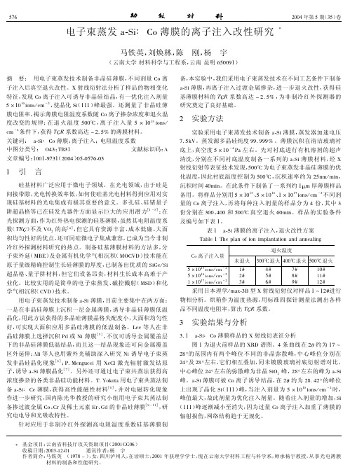
图 l SiN! 透射率曲线( A f) Fig. l Transmittance spectra of SiN! produced via routine A
方法,此法可在低温下制备含 H 少的 SiN! 薄膜而且 比较易于控制膜层的结构和成分 . 不利的是,磁控反 应溅射的%化硅薄膜的光学常数严重依赖于反应溅 射的条件,这些条件包括射频功率、总气压以及气体 比率等,所以探讨这些条件对%化硅薄膜参数的影响 机制以及找寻最优条件是必不可少的 . 有关%化硅 的制备 和 制 备 条 件 对 薄 膜 性 能 的 影 响 有 较 多 报 道[3,4],但大都集中在%化硅膜的化学成分比、折射 率、聚集密度等的研究 . 本文中针对光学上的应用而
得到的曲线,两条曲线吻合得很好 . 拟合得到的厚
度与台阶仪测得的厚度及晶振监控仪显示的厚度基
本一致,光学常数也与实际较符合 . 通过多次验证
Hale Waihona Puke 证 实拟合出来的厚度和光学常数与实际的误差很小.
以下讨论的光学常数均为拟合出来的结果 .
射 率 对 Si / N 比 率 变 化 敏 感 . 对 于 氮 气 流 量 为 2 sccm 的情况下,SiN! 薄 膜是!硅严重,吸收很大 的薄膜,这从图 4 的透射率曲线也可以看出来,通过 计算在 630 nm 处 " = 2. 4( Si3 N4 大块材料折射率为 2. 0 左右),当氮气流为 3 sccm 时,折射率和消光系 数 都 迅 速 下 降 ,折 射 率( 6 3 0 nm 处 )从2 . 4 降 到 l. 97,消光系数(500 nm 处)从 0. 03 降到 0. 008 左 右 . 继续增加氮气比率消光系数和折射率平缓下 降,变化幅度不是很大,由此可见,!硅和!氮的分 界处在 N2 / Ar 气体流量比率为 2 / l4 到 3 / l4 之间, 过了此转折点后氮已经基本饱和,继续增大 N2 比 率,此时已处于!氮区域,折射率和消光系数的变化 较小 . 溅射速率主要与射频源功率( 本实验中功率 恒定为 200 W)和溅射气体流量相关,本实验中 Ar 作为溅射气体,N2 作为反应气体 . 理论上,要得到 高折射率低吸收的 SiN! 薄膜 N2 的流量应大一点, 但随着 N2 比率的增大也增加了溅射粒子与氮分子 的碰撞几率,从而使得到达基板的粒子能量降低,不 但减慢了速率同时使成膜质量变差,膜层中空穴的 增多导致聚集密度下降,从而使折射率不断减小 . 所以通过大幅地增加 N2 流量来继续减小消光系数 是以折射率大幅下降为代价的,在需要高折射率低 吸收的光学应用上并不可取 . 我们在控制总气压为 0. 68 Pa 下改变 Ar / N2 流量比率,发现折射率几乎不 随 着 Ar / N2 流 量 的 改 变 而 变 化 ,见 图5. 由 此 可 见
含Co配合物的ZnO纳米棒复合材料光电化学性质

含Co配合物的ZnO纳米棒复合材料光电化学性质齐悦;杨洁【摘要】在氧化铟锡(Indium Tin Oxide,ITO)玻璃上制备ZnO纳米棒,并采用一种简单的自组装方法在含有ZnO纳米棒的ITO玻璃上制备Co(2.6-NDC)(4,4'-Bipy)0.5配合物.实验表明,含Co配合物并没有和ZnO纳米棒发生反应,而是比较均匀地沉积在ZnO纳米棒上.在光电化学实验中,做了仅有ZnO和含Co配合物的ZnO纳米棒的线性伏安法测试对比实验,证明含Co配合物起到了良好的催化能力.说明这种简单的自组装方法制备的金属氧化物半导体和MOFs组成的复合材料在光电化学中具有潜在的应用价值.【期刊名称】《实验室研究与探索》【年(卷),期】2018(037)010【总页数】3页(P21-23)【关键词】金属有机框架;纳米棒;光电化学;复合材料;线性伏安法【作者】齐悦;杨洁【作者单位】四川大学基础化学实验教学中心,成都610064;四川大学化学学院,成都610064【正文语种】中文【中图分类】O611.6;TB340 引言金属有机框架(Metal-Organic Frameworks, MOFs)和相关材料最近引起了相当大的关注,由于它们具有卓越的性质,如气体储存和分离,催化[1-3],而研究者们把它们用在电化学器件(例如敏感器)上却是初级阶段,可能是由于制备具有良好结构的半导体MOFs复合材料是一个巨大的挑战[4-5]。
相比纯的MOFs,这种具有良好结构的半导体MOFs复合材料展现出巨大的优点[6-7]。
例如,植入相关的MOF复合材料(如含有Au,Co等)到半导体材料(如ZnO和GaN)纳米粒子中,已经被证明在异相催化展现出良好的催化能力,当然在荧光性质和吸附性质也有相当大的挑战[8-9]。
例如,许多金属氧化物(如ZnO)是非常重要的具有半导体性质的功能材料,特别是在光电化学中的应用[10-11]。
本文提出一个简单的自组装方法制备金属氧化物半导体和MOF的复合材料,并且期望这种带有半导体结构的MOFs复合材料料在光电化学(Photoelectrochemistry,PEC)上具有潜在的应用价值。
磁控溅射沉积制备Al掺杂ZnO薄膜的棒状晶粒生长

积 、原 子 层 沉 积 、喷
雾沉积、溶胶-凝胶等各种 制 备 薄 膜 ,并得到优化的电导 率和透过率[1,4#]。其 中 ,射 频 (R F )磁控溅射工艺薄膜沉积
率高、设备能耗低,与 其 薄 膜 制 备 工 艺 相 比 ,尤其适合于 大面积薄膜工业化 ,成 太 阳 能 电 池 和 L E D 面 示行
K ey wor ds A ld o p e d Z n O ,RF magnetron sputtering,working pressure,grain growth
〇 引言
透 明 导 电 氧 化 物 (T ra n s p a re n t c o n d u c tiv e o x id e ,T C O ) 薄 膜同时具有高光透过率和电导率,已 泛 应 用 于 各 类 电 子 电
1 NICE Solar Energy Ltd,Beijing 102211 2 Beijing Engineering Research Center of Nano-structured Thin Film Solar Cell,Beijing 102211
A l-doped ZnO (A Z O ) has been considered to be one of the most potential transparent conductive oxide #TC〇 )films due to its high conduc tivity, light transmittance, abundant and low cost feature. The 30 cm x 30 cm AZO films were deposited by RF magnetron sputtering in this work. The influence of working pressure on the phase structure, m icrostructure,electrical properties as well as optical properties of AZO films were studied, and the modification of the microstructure and properties were achieved. The film deposition rate was lowered by increasing the working pressure. Thec-axis orientation preferred grain growth was weakened by increasing the worl<ing pressure. The grain size grown up by in creasing the worl<ing pressure and rod-lil<e grain growth appeared with a length of >100 nm. The minimum resistivity of 1 ■01 x 1 0 _3 ! • cm was achieved at 0 .9 3 3 P a ,the corresponding average transmittance and $ g were 7 9 . 7 / and 3 .8 2 eV. The AZO films in this work were beneficial to the TCO application.
适用于FBAR的ZnO薄膜制备及压电特性分析_苏林
适用于FBAR的ZnO薄膜制备及压电特性分析苏 林1,2,杨保和1,2*,王 芳1,2,李翠萍2,朱宇清2(1.天津大学精密仪器与光电子工程学院,天津300072;2.天津理工大学天津市薄膜电子与通信器件重点实验室,天津300384)摘要:采用射频磁控溅射法在Al电极层上制备了适用于薄膜体声波谐振器(FBAR)的ZnO薄膜,研究了溅射功率对ZnO薄膜择优取向、压电响应和极化分布的影响。
X射线衍射(XRD)测试结果表明,在一定范围内,随着溅射功率的增大,ZnO薄膜的择优取向和结晶质量得到提高;但溅射功率过大,ZnO薄膜的择优取向变差。
压电响应力显微镜(PFM)测量表明,溅射功率对薄膜的压电性能和极化取向也有很大影响,在所制备的薄膜中,多数晶粒的自发极化方向均垂直向上,表明所制备ZnO薄膜的表面主要为O截止;压电响应的振幅与薄膜的结晶质量和择优取向相关,在溅射功率为150W条件下制备的ZnO在垂直于表面方向上表现出最大压电响应振幅,同时薄膜极化取向分布的一致性最好。
关键词:薄膜体声波谐振器(FBAR);ZnO薄膜;溅射功率;择优取向;极化分布;压电响应力显微镜(PFM)中图分类号:O484 文献标识码:A 文章编号:1005-0086(2013)11-2150-06Preparation and piezoelectric properties analysis of ZnO films forfilm bulk acoustic resonatorSU Lin1,2,YANG Bao-he1,2*,WANG Fang1,2,LI Cui-ping2,ZHU Yu-qing2(College of Precision Instrument and Opto-Electronics Engineering,Tianjin University,Tianjin 300072,China;Tian-jin Key Laboratory of Film Electronic and Communication Devices,Tianjin University of Technology,Tianjin300384,China)Abstract:ZnO films used in film bulk acoustic resonator(FBAR)were deposited on the aluminum bot-tom electrode layers by radio frequency magnetron sputtering,and how the sputtering power influencesthe preferred orientation,piezoelectric response and polarity distribution of the prepared films is investi-gated.X-ray diffraction(XRD)measurements indicate that in a certain range,increasing the sputteringpower is conducive to the improvement of crystal quality and c-axis orientation,and meanwhile,we alsoobserve a decline in the c-axis orientation of the film deposited at too much higher sputtering power.Simultaneous imaging of the surface topography,as well as the amplitude and phase of the piezoelectricresponse is performed by piezoresponse force microscopy(PFM),and the results show that the sputte-ring power has great influence on the piezoelectric activities and polarization orientation of ZnO films.The majority of the grains within the prepared films has upward spontaneous polarization orientation,in-dicating that the top surfaces of the films are mainly O terminated.The amplitude of the out-of-planepiezeresponse depends on the crystal quality and preferred orientation of the films.The film deposited atthe sputtering power of 150Wexhibits better O-polarity uniformity and greater piezeresponse amplitudein the direction perpendicular to the film surface than those of the other samples.Key words:film bulk acoustic resonator(FBAR);ZnO films;sputtering power;preferred orientation;polarity distribution;piezoresponse force microscopy(PFM)光电子·激光第24卷第11期 2013年11月 Journal of Optoelectronics·Laser Vol.24No.11 November 2013* E-mail:bhyang@tjut.edu.cn收稿日期:2013-04-23 修订日期:2013-05-20基金项目:国家高技术研究发展(863)计划(2013AA030801)、天津市科技支撑计划(10ZCKFGX01200)、天津市科技计划(10SYSYJC27700)和天津市高等学校科技发展基金(2006BA31)资助项目DOI:10.16136/j.joel.2013.11.0091 引 言 ZnO具有良好的激光发射性能,在激光器、发光二极管及太阳能电池等领域有重要的应用[1~3]。
氮掺铟锡锌薄膜晶体管的制备及其光电特性

氮掺铟锡锌薄膜晶体管的制备及其光电特性李治玥;吕英波;赵继凤;宋淑梅;杨波波;辛艳青;王昆仑;杨田林【摘要】In-Sn-Zn oxide thin-film transistors were deposited at different nitrogen flow rates on P-Si<100> substrate by RF magnetron sputtering. The influence of nitrogen on the structure, optical and electrical properties and stabilities of ITZO TFTs was studied. The results show that nitrogen has no obvi-ous effect on the structure of ITZO films and all thin films are amorphous. The average transmittance of all ITZO films approach or exceed 90% in the visible region and the optical band gaps are 3. 28-3. 32 eV. When the nitrogen flow rates increase to 4 mL/min during the sputter deposition, the ITZO TFTs with low interface state density(~4. 3 × 1011 cm-2 ) show excellent electrical properties, the sub-thresh-old swing is 0.39 V/dec and on/off ratio is 106 operated with the field-effect mobility (μFE ) of 18. 72 cm2/(V?s). Moreover, the TFTs show better stability than others in the positive gate bias stress test. Overall, the suitable addition of nitrogen can improve the electrical performance and the stability of the ITZO TFTs by the passivation of oxygen vacancies and the drop of interface state density.%以P型<100>硅作为衬底,采用射频磁控溅射技术,在室温下制备了氮掺杂氧化铟锡锌薄膜晶体管(ITZO TFTs),研究了氮气流量对氧化铟锡锌薄膜晶体管结构、光学、电学特性以及稳定性的影响.实验结果表明:在不同氮气流量条件下制备的氧化铟锡锌薄膜均为非晶态,在可见光范围内的平均透过率均在90%左右,光学带隙数值在3.28~3.32 eV之间变化.在氮气流量为4 mL/min时制备的ITZO TFTs,有源层与栅极电介质界面处的界面态密度(Nmaxs)仅为4.3×1011 cm-2,场效应迁移率(μFE)为18.72 cm2/(V?s),开关比(Ion/of)为106,亚阈值摆幅(S)为0.39 V/dec,电学性能最优.栅极正偏压应力测试结果表明,该器件具有最强的稳定性.因此,适量的氮掺杂可有效地实现器件氧空位的钝化,降低器件的界面态密度,提高ITZO TFTs的电学性能及稳定性.【期刊名称】《发光学报》【年(卷),期】2017(038)012【总页数】7页(P1622-1628)【关键词】氧化铟锡锌薄膜晶体管;射频磁控溅射;氮掺杂;界面态密度【作者】李治玥;吕英波;赵继凤;宋淑梅;杨波波;辛艳青;王昆仑;杨田林【作者单位】山东大学空间科学与物理学院, 山东威海 264209;山东大学空间科学与物理学院, 山东威海 264209;山东大学空间科学与物理学院, 山东威海264209;山东大学空间科学与物理学院, 山东威海 264209;山东大学空间科学与物理学院, 山东威海 264209;山东大学空间科学与物理学院, 山东威海 264209;山东大学空间科学与物理学院, 山东威海 264209;山东大学空间科学与物理学院, 山东威海 264209【正文语种】中文【中图分类】TN321+.5薄膜晶体管(TFT)作为显示器有源驱动的核心部件,被广泛应用于大规模集成电路和平板显示领域。
集成电路制造论文离子注入掺杂对ZnO薄膜性能的影响综合分析说明(可编辑..
离子注入掺杂对ZnO薄膜性能的影响The influence of ion implantation on the ZnO thin film姓名:郝秀秀西安电子科技大学摘要氧化锌ZnO是一种重要的宽禁带室温下Eg--3.37eV直接带隙半导体材料。
离子注入是将具有高功能的掺杂离子引入到半导体中的一种工艺.其目的是改变半导体的载流子浓度和导电类型.本论文是利用离子注入技术进行掺杂和热退火处理ZnO薄膜改性。
利用溶胶凝胶方法在石英玻璃衬底上制备了ZnO薄膜,将能量56 keV、剂量1×10"cm-2的Zn离子注入到薄膜中。
离子注入后,薄膜在500~900℃的氩气中退火,利用X射线衍射谱、光致发光谱和光吸收谱研究了离子注入和退火对ZnO薄膜结构和光学性质的影响。
结果显示:衍射峰在约700℃退火后得到恢复;当退火温度小于600℃时,吸收边随着退火温度的提高发生蓝移,超过600℃时,吸收边随着退火温度的提高发生红移。
关键词:ZnO薄膜;离子注入;退火温度;吸收;光致发光。
ABSTRACT Zinc oxide ZnO is a kind of important wide forbidden band Eg at room temperature-3.37 eV direct bandgap semiconductor materials. Ion implantation iswill have high function into thedopingisemiconductor process. The aim is to change the charge carriers concentration and semiconductor conductive type The present paper is using ion implantation technology and thermal annealing processing doped ZnO thinfilm modification. Using sol-gel method in quartz glass substrates gel preparation ZnO films, the energy 56 keV, dose 1 X 10 "cm-2 of Zn ion implantation to film. Ion implantation, film in 500 ~ 900 ℃ in the argon annealing, X-ray diffraction spectrum, the light spectrum and light absorption spectrum to send the ion implantation and annealing ZnO thin film on the influence of the structure and optical properties The results showed that: about 700 ℃in the diffraction peak after annealing restoration; When the annealing temperature is less than 600 ℃, the temperature of the annealing edge with absorb blue to move, raise happen more than 600 ℃, the temperature of the edge with absorption annealing improve red shift occurred.Keywords: ZnO films; Ion implantation; Annealing temperature; Absorption; The light to shine 引言作为宽禁带半导体材料,ZnO近年来引起了广泛的研究兴趣。
磁控溅射制备ZnO薄膜及其掺杂的研究
!"#$%& ’() *#+,(- #. /(0 1,234 56 7’-(8%"#( 9+:%%8",("<40. =>,?640. @A;BC#,DE DF/>;G(#H,D6@ </#;IC#,J40. ?F/#H
(!"##$%$ "& ’()$*($ , +"*%,-. /*)0$12)34 , ’,.*%,.) -+++1! , !,)*.)
光强 N -%3%
课题采用射频与直流辉光放电的磁控溅射系统,射 频频率为 >!?@A B<C。图 ! 是 :2=78 在特定工作条 件下的发射光谱。对等离子体的发射光谱进行分 析,以实现对等离子体参数的定性分析,并对材料 制备的工艺过程进行实时监控
[@]
。
:2=78 (8 H- 8FF P)
效 的 掺 杂 ( :. 掺 杂 、 ; 掺 杂 、 :.=; 共 掺 杂 ) ,并
IJ
(掺 ; )
I@
(掺 :.=; )
"#$%8 &’( #/-$(0 )4 $.)5 L#0,’-2$(
微纳电子技术
!""# 年第 $" 期
7#8
!"#$%&’&%()(#*$%&"# +(#,&%)%-./ !"#$%&’ ())*
纳米材料与结构
!"#$%"&’()"* + ,&(-.&-(’
@ /#1 的溅射清洗,溅射时间都为 !F /#1。 I> 样品
射频磁控溅射制备Mn掺杂ZnO薄膜的结构和铁磁性能研究
收稿日期:2020-08-03基金项目:国家自然科学基金(61176010,61172027)通信作者:阳生红,副教授,博士,主要从事氧化物薄膜制备与性能研究㊂E-mail :stsyshh @mail .sysu .edu .cn电子元件与材料Electronic Components and Materials第40卷Vol .40第3期No .33月Mar2021年2021射频磁控溅射制备Mn 掺杂ZnO 薄膜的结构和铁磁性能研究阳生红1,蒋志洁1,张曰理2(1.中山大学物理学院,广东广州㊀510275;2.中山大学材料科学与工程学院,广东广州㊀510275)摘㊀要:采用射频磁控溅射法制备了Mn 掺杂ZnO (Zn 1-x Mn x O ,其中x =0,0.03,0.06)薄膜㊂通过X 射线衍射(XRD )㊁拉曼光谱(Raman )㊁原子力显微镜(AFM )和超导量子干涉磁强计(SQUID )对薄膜结构和磁性能进行了研究㊂XRD 和Raman 研究表明,不同浓度Mn 掺杂ZnO 薄膜均为ZnO 的六角纤锌矿结构,并沿(002)晶面择优取向,未检测到Mn 以及与Mn 相关的氧化物杂相㊂随着Mn 掺杂浓度的增大,薄膜的结晶质量下降,晶粒尺寸减小㊂AFM 研究结果与XRD 和Raman 结果相一致㊂SQUID 测量表明Mn 掺杂ZnO 薄膜表现出室温铁磁性,Mn 掺杂量x 为0.03和0.06时,在1.59ˑ106A /m 磁场下的磁化强度分别为0.12和0.18A ㊃m 2/kg ㊂随着Mn 掺杂浓度的增大,磁化强度和矫顽力增大㊂基于XRD ㊁Raman 和AFM 研究结果,可以认为Mn 掺杂ZnO 薄膜的铁磁性与杂相无关,属于样品的本征磁性㊂关键词:Zn 1-x Mn x O 薄膜;磁控溅射;结构;铁磁性中图分类号:O 484.4;TN 304文献标识码:ADOI :10.14106/j .cnki .1001-2028.2021.1549引用格式:阳生红,蒋志洁,张曰理,等.射频磁控溅射制备Mn 掺杂ZnO 薄膜的结构和铁磁性能研究[J ].电子元件与材料,2021,40(3):234-238.Reference format :YANG Shenghong ,JIANG Zhijie ,ZHANG Yueli ,et al.Structural and ferromagnetic properties of Mn doped ZnO thin films prepared by RF magnetron sputtering [J ].Electronic Components and Materials ,2021,40(3):234-238.Structural and ferromagnetic properties of Mn doped ZnO thin filmsprepared by RF magnetron sputteringYANG Shenghong 1,JIANG Zhijie 1,ZHANG Yueli 2(1.School of Physics,Sun Yat -sen University,Guangzhou㊀510275,China;2.School of Materials and Engineering,Sun Yat -sen University,Guangzhou㊀510275,China)Abstract :Mn doped ZnO (Zn 1-x Mn x O ,x =0,0.03,0.06)thin films were prepared by RF magnetron sputtering.Thestructural and ferromagnetic properties of these films were characterized by X -ray diffraction (XRD ),Raman spectroscopy (Raman ),atomic force microscopy (AFM )and superconducting quantum interference magnetometer (SQUID ).XRD and Raman results show that the Mn doped ZnO (Zn 1-x Mn x O ,x =0,0.03,0.06)thin films have a hexagonal wurtzite structure of pure ZnO with highly (002)preferential orientation.No Mn element and oxides can be detected.As the Mn dopant concentration increases ,the crystalline quality and grain size of the films decrease.The AFM results are consistent with XRD and Raman.SQUID measurements show that Mn doped ZnO films exhibit room temperature ferromagnetism ,and the magnetization at 1.59ˑ106A /m magnetic field is 0.12and 0.18A ㊃m 2/kg when the Mn dopant amount x is 0.03and 0.06respectively.With higher Mn dopant concentration ,the magnetization and coercivity increase.According to XRD ,Raman and AFM results ,it can be deduced that the ferromagnetism of the Mn doped ZnO films is independent of the impurity phases and inherent to the samples.Key words :Zn 1-x Mn x O thin films ;magnetron sputtering ;structure ;ferromagnetism阳生红,等:射频磁控溅射制备Mn掺杂ZnO薄膜的结构和铁磁性能研究㊀㊀稀磁半导体(DMS)是通过在半导体中掺杂磁性离子而获得铁磁性(FM)的一种新型材料㊂其中磁性离子掺杂ZnO是最有前途和研究最广泛的DMS之一[1-4]㊂自从Ditel等从理论上预言Mn掺杂ZnO可能表现出室温铁磁性(RTFM)以来[4],许多研究小组相继从理论和实验上证实了过渡元素(TM)掺杂ZnO是制备DMS的有效方法[1-3,5-6]㊂然而,关于TM掺杂ZnO稀磁半导体中掺杂磁性离子的作用仍然存在很多争议,甚至出现了相互矛盾的结论㊂DMS的FM起源也具有争议性[1-3],有人认为是由金属团簇㊁缺陷引起的㊂这是目前研制RTFM的ZnO基DMS的主要障碍㊂众所周知,ZnO中的本证缺陷有氧空位(V O)㊁间隙锌原子㊁锌空位以及间隙氧原子㊂Mn因其3d壳层具有最多的未成对电子(3d5),从实验和理论的角度研究Mn掺杂ZnO的FM引起了研究者的广泛兴趣[1-6]㊂Mn掺杂ZnO的FM主要认为来源于晶格缺陷和二价Mn离子替代Zn离子㊂也有研究报道Mn掺杂ZnO材料中的FM来自于Zn和O晶格位上的缺陷[6-8]㊂一定量的Mn掺杂能使居里温度提高到室温[4]㊂此外,氧化锌中V o浓度的变化与FM的强弱变化是一致的,说明FM是基于V o诱导机制[9]㊂大部分实验研究认为Mn掺杂ZnO材料中的FM属于样品的本征磁性㊂当然,Mn掺杂ZnO的FM对制备条件和制备方法十分敏感㊂这是因为不同的制备方法会导致材料中产生的缺陷不同所致[5,8]㊂实现室温铁磁性及探索其磁性来源是当今DMS的重要研究方向㊂近几年,Mn掺杂ZnO基DMS的研究取得了巨大的进步㊂但不同的制备方法㊁温度㊁气氛以及材料的结构形态都会引起磁性能的变化,开展不同制备条件和制备方法研究,对理解Mn掺杂ZnO的FM来源是非常有意义的㊂射频磁控溅射法可以更好地控制沉积参数(如:沉积速率㊁衬底温度㊁工作气压等),并具有比脉冲激光沉积法(PLD)和分子束外延法(MBE)相对简单和低成本等优点,是制备Mn掺杂ZnO薄膜普遍采用的方法之一㊂关于溅射参数(如工作气压㊁衬底温度㊁射频(RF)源或直流(DC)源㊁衬底旋转速度和衬底材料等)对ZnO或掺杂ZnO薄膜的结构和性能的影响已有大量文献报道[10-12]㊂本文采用射频磁控溅射法制备了不同浓度Mn掺杂ZnO薄膜,研究了Mn掺杂浓度对薄膜结构和磁性能的影响㊂并对Mn掺杂ZnO薄膜中FM的来源进行了讨论㊂1㊀实验实验使用的靶材为直径两英寸的Mn掺杂ZnO (Zn1-x Mn x O,其中x=0,0.03,0.06)陶瓷靶,购自合肥科晶材料技术有限公司㊂采用射频磁控溅射法在Si(100)衬底上制备了Zn1-x MnxO(x=0,0.03,0.06)薄膜㊂在镀膜之前,Si(100)衬底依次经无水乙醇,60ħ丙酮溶液超声清洗10min,无水乙醇浸泡20min,然后去离子水反复冲洗后在真空干燥箱里烘干㊂将清洗之后的衬底置于溅射室中,系统真空抽至6.5ˑ10-6 Pa,然后充入高纯(99.999%)氩气和氧气,保持Ar流量为26mL/min㊁O2流量为4mL/min(即氩氧体积比为26ʒ4)的条件不变,使溅射室工作气压为2.5Pa㊂调整衬底与靶间距离为7cm,等衬底温度达到700ħ时,首先进行预溅射15min,以清除靶材表面的污染物㊂然后将溅射功率调至100W,保持工作气压㊁靶材与衬底的距离㊁氩氧比㊁溅射时间(120min)以及衬底温度(700ħ)等参数不变,分别对不同Mn掺杂浓度的ZnO陶瓷靶进行溅射,制备出Zn1-x Mn x O(x=0, 0.03,0.06)薄膜样品㊂用台阶仪测得薄膜厚度约为230nm㊂用日本理学(RIGAKU)X射线粉末衍射仪(D-MAX2200VPC03030502)和英国雷尼绍公司生产的激光显微拉曼光谱仪(Renishaw inVia)研究薄膜的相结构㊁结晶取向和结晶度㊂用布鲁克(Bruker)公司生产的扫描探针显微镜(Dimension Fastscan)研究样品的表面形貌㊂采用美国Quantum Design磁学测试系统(SQUID磁强计MPMS3)对样品进行磁性测量㊂2㊀结果与讨论2.1㊀Mn掺杂浓度对Zn1-xMnxO薄膜结构的影响㊀㊀图1为不同浓度Mn掺杂Zn1-x Mn x O(x=0,0.03, 0.06)薄膜样品的XRD图谱㊂从图1可以看出,未掺杂和Mn掺杂Zn1-x Mn x O薄膜样品均呈现显著的(002)择优取向,在整个衍射角范围内未发现其他衍射峰出现㊂这表明未掺杂和Mn掺杂Zn1-x Mn x O薄膜样品均具有很好的六角纤锌矿结构,属P63mc空间群㊂Mn 掺杂后未出现金属Mn㊁氧化物和其他第二相㊂Mn掺杂ZnO仍保持ZnO的六角纤锌矿结构,说明Mn原子替代了Zn原子晶格位置,属替位式掺杂㊂随着Mn掺杂量的增大,(002)衍射峰的强度减弱,峰位略向小衍射角方向移动(如图1(b)所示)㊂这表明Mn掺杂不仅导致薄膜的结晶质量下降,而且使(002)晶面的间距增大㊂导致薄膜结晶质量下降的原因可能是因为Mn的掺入导致一些缺陷(如:氧空位㊁锌间隙原子㊁㊃532㊃电子元件与材料边界位错及堆垛层错等)所致,而Mn 的掺入使(002)晶面间距增大是由于Mn 离子半径(80pm )大于Zn 离子半径(74pm )所致㊂Mn 掺杂量x 为0,0.03和0.06的薄膜样品,其(002)衍射峰的半峰宽(FWHM )分别为0.523ʎ,0.541ʎ和0.763ʎ,随着Mn 掺杂量的增加而增加㊂利用Debye Scherrer 公式D =0.89λ/(βcos θ)(这里β为(002)衍射峰的FWHM ,θ是布拉格衍射角,λ=0.154nm ,为X 射线的波长)对不同浓度Mn 掺杂Zn 1-x Mn x O 薄膜的晶粒大小进行了估算㊂对Mn 掺杂量x 为0,0.03和0.06的Zn 1-x Mn x O 薄膜,计算得到的晶粒尺寸分别为14.2,12.4和9.5nm ㊂可见晶粒尺寸随Mn 掺杂量的增加而减小㊂图1㊀(a )不同浓度Mn 掺杂Zn 1-x Mn x O (x =0,0.03,0.06)薄膜样品的XRD 图谱;(b )(002)衍射峰的放大图像Fig .1㊀(a )XRD patterns of Zn 1-x Mn x O (x =0,0.03,0.06)thin films ;(b )The enlarged (002)peaks ofZn 1-x Mn x O (x =0,0.03,0.06)thin films㊀㊀图2为不同浓度Mn 掺杂Zn 1-x Mn x O (x =0,0.03,0.06)薄膜样品在波长为514nm 的激发光下测量得到的拉曼(Raman )光谱㊂从图2中可以看到Raman 特征散射峰主要出现在200~600cm -1区域内㊂所有薄膜样品在437.6cm -1位置显现出一个Raman 散射峰,该峰为E 2(High )振动模式,是六角纤锌矿结构ZnO 的特征Raman 散射峰,该Raman 散射峰表明Zn 1-x Mn x O (x =0,0.03,0.06)薄膜均形成良好的六角纤锌矿结构[12],这与XRD 结果是相吻合的㊂在488.8cm -1和590.2cm-1位置呈现出的两个Raman 散射峰与Zn 1-x Mn x O (x =0,0.03,0.06)薄膜中的氧空位㊁Zn 间隙原子以及表面或界面光子有关[13],是缺陷引起的本征振动㊂峰的强弱表明薄膜样品中的氧空位㊁Zn 间隙原子等缺陷的多少㊂未发现Mn 氧化物和其他杂相相关的Raman 散射峰,说明Mn 掺杂已经进入到ZnO 晶格中并替代了Zn 离子㊂这一点也是与XRD 结果相一致的㊂基于Raman 光谱可以认为:Mn 掺杂Zn 1-x Mn x O (x =0,0.03,0.06)薄膜样品均具有良好的ZnO 六角纤锌矿结构,薄膜中存在一定量的晶格缺陷㊂图3为不同浓度Mn 掺杂Zn 1-x Mn x O (x =0,0.03,0.06)薄膜表面的二维和三维AFM 形貌图㊂所有样品的晶界都很明显,表面比较平整且粗糙度比较低,晶粒沿一个方向生长㊂从二维AFM 形貌图中可以看到,薄膜表面为分布均匀的多孔结构,孔径大小随Mn 掺杂量x 的变化而变化㊂当x 为0,0.03和0.06时,相应的表面均方根粗糙度分别为14.5,7.98和3.29nm ㊂三维AFM 形貌图为中空的锥柱状结构,高低起伏均匀㊂AFM 分析表明,随着Mn 掺杂量的增加,晶粒尺寸逐渐变小,说明Mn 掺杂已进入ZnO 晶格并且通过替位方式改变了ZnO 的结构㊂图2㊀不同浓度Mn 掺杂Zn 1-x Mn x O (x =0,0.03,0.06)薄膜的拉曼光谱Fig .2㊀Raman spectra of Zn 1-x Mn x O (x =0,0.03,0.06)thin films㊃632㊃阳生红,等:射频磁控溅射制备Mn 掺杂ZnO薄膜的结构和铁磁性能研究图3㊀不同浓度Mn 掺杂Zn 1-x Mn x O (x =0,0.03,0.06)薄膜表面的二维和三维AFM 形貌图㊂(a )㊁(d )x =0;(b )㊁(e )x =0.03;(c )㊁(f )x =0.06Fig .3㊀Two and three dimensional AFM images of Zn 1-x Mn x O (x =0,0.03,0.06)thin films.(a )and (d )x =0;(b )and (e )x =0.03;(c )and (f )x =0.062.2㊀Mn 掺杂浓度对Zn 1-x Mn x O 薄膜磁性能的影响㊀㊀图4是不同浓度Mn 掺杂Zn 1-x Mn x O (x =0,0.03,0.06)薄膜样品的室温磁滞(M -H )回线㊂由图4看出,未掺杂ZnO (x =0)薄膜样品在室温下只显示出顺磁性,当Mn 掺杂ZnO 薄膜样品在室温下显示出明显的磁滞回线,具有室温铁磁性㊂对Mn 掺杂量x 为0.03和0.06时,矫顽力(H c )和1.59ˑ106A /m 磁场下的磁化强度(M )分别为2.16ˑ104A /m ,0.12A ㊃m 2/kg 和2.99ˑ104A /m ,0.18A ㊃m 2/kg ㊂Mn 掺杂Zn 1-x Mn x O 薄膜样品的室温铁磁性随着Mn 掺杂量的增加而加强㊂这是由于随着Mn 掺杂量的增加,替代Zn 的Mn 离子增多,导致铁磁交换作用增加的结果㊂对于掺杂ZnO 薄膜样品的铁磁性起源问题仍存在争议,一方面人们认为样品的铁磁性来源于金属团簇或第二相,另一方面认为是样品掺杂的本征性质㊂本工作中制备的Mn 掺杂Zn 1-x Mn x O 薄膜样品不难排除Mn 团簇㊁Mn 的氧化物和可能的第二相对薄膜样品铁磁性的贡献㊂从XRD 和Raman 图谱可以看出,所有样品均保持良好的ZnO 六角纤锌矿结构,未出现其他杂相㊂可排除薄膜样品存在Mn 团簇㊁Mn 的氧化物和可能的第二相的情况㊂因此,本工作中制备的Mn 掺杂Zn 1-x Mn x O 薄膜样品的铁磁性为材料的本征性质,即Mn 替代Zn 的铁磁交换和反铁磁交换的竞争㊂很多报道认为氧空位对Mn 掺杂ZnO 和Co 掺杂ZnO 薄膜的铁磁性起着重要的作用[14-15]㊂考虑到所采用的制备方法和结构分析的结果,本工作中制备的Mn 掺杂Zn 1-x Mn x O 薄膜样品虽然具有良好的ZnO 六角纤锌矿结构,但薄膜内也同时存在一定数量的晶格缺陷(如:氧空位㊁Zn 间隙原子等)㊂根据束缚磁极化子(BoundMagnetic Polaron )模型[16-17],当氧空位浓度达到一定值时,邻近的磁极化子相互交叠,从而导致邻近的Mn 离子之间产生铁磁交换作用㊂这是Mn 掺杂Zn 1-x Mn x O 薄膜样品中观测到室温铁磁性的主要原因㊂随着Mn 掺杂量的增加,氧空位或缺陷均有所增加,从而提供了更多的铁磁耦合中心,故样品表现出更强的铁磁性㊂图4㊀不同Mn 掺杂Zn 1-x Mn x O (x =0,0.03,0.06)薄膜样品的室温磁滞回线Fig .4㊀Room temperature M -H curves of Zn 1-x Mn x O thin filmswith x =0,0.03,0.06㊃732㊃电子元件与材料3 结论利用射频磁控溅射法制备了不同浓度Mn掺杂Zn1-x Mnx O薄膜,并采用XRD㊁Raman㊁AFM和SQUID对其结构㊁表面形貌和铁磁性进行了研究㊂XRD和Raman研究没有发现第二相,所有薄膜样品均保持良好的ZnO六角纤锌矿结构,且沿c轴择优取向生长㊂AFM测量表明样品中的颗粒分布均匀,没有出现团聚物㊂SQUID测量结果表明,未掺杂ZnO薄膜在室温下只显示出顺磁性,而Mn掺杂ZnO薄膜在室温下显示出明显的铁磁性,且随着Mn掺杂量的增大,样品的矫顽力(H c)和磁化强度(M)均增大㊂基于XRD㊁Raman和AFM研究结果,可以认为本工作中发现的Mn掺杂ZnO薄膜的室温铁磁性是其本征性质,其室温铁磁性的来源可通过束缚磁极化子模型解释㊂参考文献:[1]Ando K.Materials science:seeking room-temperature ferromagneticsemiconductors[J].Science,2006,312:1883-1885. [2]Sharma P,Gupta A,Rao K V,et al.Ferromagnetism above roomtemperature in bulk and transparent thin films of Mn-doped ZnO[J].Nature Materials,2003,2:673-677.[3]Chen B,Yu Q X,Gao Q Q,et al.Structural reconstruction anddefects transition in mediating room temperature ferromagnetism in Co-doped ZnO film[J].Applied Physics Letter,2013,102:132405.[4]Dietl T,Ohno H,Matsukura F,et al.Zener model description offerromagnetism in zinc-blende magnetic semiconductors[J].Science,2000,287:1019-1022.[5]Djerdj I,Jaglicic'Z,Arcon D,et al.Co-doped ZnO nanoparticles:minireview[J].Nanoscale,2010,2:109.[6]Mhlongo G H,Shingange K,Tshabalala Z P,et al.Room temperatureferromagnetism and gas sensing in ZnO nanostructures:influence ofintrinsic defects and Mn,Co,Cu doping[J].Applied Surface Science, 2016,390:804-815.[7]Qi B,Ólafsson S,Gíslason H P.Vacancy defect-induced d0ferromagnetism in undoped ZnO nanostructures:controversial origin and challenges[J].Progress in Materials Science,2017,90:45 -74.[8]Ilyas U,Rawat R S,Wang Y,et al.Alteration of Mn exchangecoupling by oxygen interstitials in ZnOʒMn thin films[J].Applied Surface Science,2012,258:6373-6378.[9]Wang Q,Sun Q,Chen G,et al.Vacancy-induced magnetism inZnO thin films and nanowires[J].Physical Review B,2008, 77:205411.[10]Mahdhi H,Ayadi Z B,Gauffier J L,et al.Influence of substratetemperature on the properties of nanostructured ZnO thin films grown by RF magnetron sputtering[J].Journal of Electronic Materials, 2016,45:557-565.[11]Jayaraman V K,Kuwabara Y M,Álvarez A M,et al.Importance ofsubstrate rotation speed on the growth of homogeneous ZnO thin films by reactive sputtering[J].Materials Letters,2016,169:1-4. [12]Srinatha N,No Y S,Kamble V B,et al.Effect of RF power on thestructural,optical and gas sensing properties of RF-sputtered Al doped ZnO thin films[J].RSC Advances,2016,6:9779-9788.[13]Wong L H,Lai Y S.Effects of radio frequency power on structural,optical,and electronic properties of sputter-deposited ZnOʒB thin films[J].Applied Physics A,2018,124:462.[14]Sharma V K,Varma G D.Oxygen vacancies induced roomtemperature ferromagnetism in hydrogenated Mn-doped ZnO[J].Journal of Applied Physics,2007,102:056105.[15]Bao H,Zhu D,Ma X,et a1.Grit influence of the oxygen vacancieson the ferromagnetism in the Co doped ZnO films[J].Applied Surface Science,2007,253:6892-6895.[16]Coey J M D,Venkatesan M,Ftzgerald C B.Donor impurity bandexchange in dilute ferromagnetic oxides[J].Natural Materials, 2005,4:173.[17]Griffin K A,Pakhomov A B,Wang C M,et a1.Intrinsicferromagnetism in insulating cobalt doped anatase TiO2[J].Physics Review Letters,2005,94:157204.㊃832㊃。
射频溅射ZnO薄膜的晶体结构和电学性质
射频溅射ZnO 薄膜的晶体结构和电学性质黄静华 李德杰(清华大学电子工程系 北京 100084)Structures and Electric Properties of RF Sputtered Zn O FilmsHuang Jinghua ,Li Dejie(Department o f Electronic Engineering ,Tsinghua University ,Beijing ,100084,China ) A bstract Zn O films can be a promising material used in the electron transmission and acceleration layers in a field emission flat panel display because of its wide band gap (3.1eV )and low affinity (3.0eV ).The structures and electric properties of the ZnO films ,grown by RF magnetron sputtering ,were studied with X -ray diffraction spectroscopy (XRD ),scanning electron spectroscopy (SE M ).The results showed that the substrate temperature and the partial pressures of oxygen and argon gasses during sputtering affect the quality of the films .XRD results showed that high substrate temperature promotes crystallization of the fil m .The highl y textured film is made up of grains with their c -axis normal to the surface .The average size of crystal grains range about 50~60nm ,with a preferential growth orientation in (002)direction .Addition of s mall amount of oxygen may increase the breakdown electric field strength of the films .For example ,when the sputterin g gas was Ar +O 2(25%),the breakdown electric field stren gth increases from 0.17V /10nm to 0.35V /10nm ,as the substrate temperature rises from room temperature to 180℃. Keywords ZnOthin film ,RF sputtering ,Field emission displa y 摘要 氧化锌(Zn O )具有较宽的带隙(3.1eV )和较低的亲合势(3.0eV ),有可能用作薄膜场发射阴极中的电子传输层材料。
- 1、下载文档前请自行甄别文档内容的完整性,平台不提供额外的编辑、内容补充、找答案等附加服务。
- 2、"仅部分预览"的文档,不可在线预览部分如存在完整性等问题,可反馈申请退款(可完整预览的文档不适用该条件!)。
- 3、如文档侵犯您的权益,请联系客服反馈,我们会尽快为您处理(人工客服工作时间:9:00-18:30)。
1
)1,2,3 , Dongyun Wan ( and Fuqiang Huang (
ý ) áÄÖ)
2∗
பைடு நூலகம்
, Zhou Wang (
2
÷) ,
2
Suzhou Institute of Nano-tech and Nano-bionics, Chinese Academy of Sciences, Suzhou 215123, China 2 CAS Key Laboratory of Materials for Energy Conversion, Shanghai Institute of Ceramics, Chinese Academy of Sciences, Shanghai 200050, China 3 Institute of Semiconductors, Chinese Academy of Sciences, Beijing 100083, China ∗ Corresponding author: wandy@ Received April 15, 2011; accepted April 28, 2011; posted online August 3, 2011
October 10, 2011
sealed by an upside-down crucible buried in graphite. When heated, the limited oxygen in the upside-down crucible reacted with the graphite. Carbon monoxide (CO) was produced, creating a reducing atmosphere in the inner crucible. The oxygen atoms in the ZnO lattice and on the grain boundaries were withdrawn by the reduced atmosphere, resulting in an oxygen deficient state in the target. The resistivity of the ZnO targets is 0.185 Ω·cm at room temperature. ZnO films were deposited in a high vacuum magnetron sputtering system (JGP450) with a base pressure of 2.0 × 10⁻⁴ Pa, under a flow of high-purity Ar/O2 mixture (0.9% O2 content, 15 sccm). DC magnetron sputtering was employed to deposit films with the home-made oxygen-deficient ZnO target on glass slides with a holdertarget distance of 90 mm. During the sputtering, pressure and the sputtering power were maintained at 1.2 Pa and 80 W, respectively. When used as the diffusion barrier in thin film CIGS solar cells, the thickness of the i-ZnO layer is normally controlled between 60–120 nm. In the current study, the film was deposited for 2 min and the thickness was measured to be 80 nm. One 800nm sample was prepared for the accuracy of characterization. For comparison, another RF-sputtered ZnO film deposited from the commercial target was also prepared with the same thickness. Bruker AXS Advance D8 Focus diffractometer using CuKα radiation was applied for X-ray diffraction (XRD) measurement. Field emission scanning electron microscopy (FE-SEM) was performed using LEO-1530VP. In combination with the use of a profilometer (Dektak 150), FE-SEM was used to evaluate the surface morphologies and thickness of the ZnO films. Transmission measurements were conducted on a Hitachi U-4100 spectrometer in the wavelength range of 300–2 200 nm. The van der Pauw method was used with an Accent HL5580PC to measure the electrical transport properties, including electrical resistivity, carrier concentration, and hall mobility, at room temperature. A magnetic field of 3 T was applied in these measurements. The XRD patterns of the as-deposited i-ZnO thin films are shown in Fig. 2. Three samples are shown to be oriented along the (002) direction, indicating a wellpronounced (002) preferential growth. The XRD peaks of the DC-80 W-80 nm ZnO film are weak and broad. As the thickness increased to 800 nm for the DC-or RF- sputtered films, the full-width at half-maximum (FWHM) of the (002) planes in the respective film decreased and the peak intensity measured in counts per second (CPS) increased, as listed in Table 1. For the same thickness, the DC-sputtered sample showed sharper peaks and stronger intensity than its RF-sputtered counterpart, indicating better crystallization. The optical properties of the as-deposited ZnO films are depicted in Fig. 3. All the as-deposited samples showed a high transmittance of approximately 90% in the entire spectrum range of 400–2 100 nm, and the DCsputtered film achieved similar transmittance as the RFsputtered one. The remaining extremely high transmittance in the near-infrared region is consistent with the low carrier concentration of the films, shown in Table 1, which depresses the plasma frequency. The FE-SEM images of the surface morphologies of the
High resistance transparent intrinsic zinc oxide (i-ZnO) thin film has been widely used as the front electrode in transparent electronics and photovoltaic devices because of its low cost and nontoxicity. Owing to its unique characteristics of high transparency and adjustable resistivity in a certain range, the use of i-ZnO thin films as diffusion barrier layers of a-Si/µc-Si, CdTe, and CIGS thin-film solar cells has been advantageous[1−7]. The i-ZnO layer not only hampers the interdiffusion of the contacts and the p-n junction, but also prevents the short-circuiting of the back- and front-contacts to enhance the uniformity and stability of the cell[8,9] . ZnO films have been prepared by several methods, such as magnetron sputtering, pulsed laser deposition (PLD), molecular beam epitaxy (MBE), physical vapor deposition (PVD), and metal organic chemical vapor deposition (MOCVD)[10−14] . Among these methods, magnetron sputtering is the most widely used technique because of its favorable features, such as lower process temperature, good film adhesion, and good uniformity of thickness distribution. Generally, ceramic intrinsic ZnO target is used and the radio frequency (RF) sputtering process is mandatory because of the poor conductivity of the target[15] . In industrial applications, RF power supply is difficult to be used in mass productions due to its high cost, whereas the direct current (DC) power supply platform is more popularly utilized because of its higher technique uniformity, controllable function, and lower cost. Researchers have tried to fabricate high resistance ZnO thin films with the conductive ZnO:Al (AZO) target by the DC sputtering method under a high oxygen atmosphere partial pressure[16−19] . However, the very high oxygen content in the plasma would damage the inner frontier films, which is deleterious to device