HM10.0day1_中文
UG材料库UG10.0中英文对照
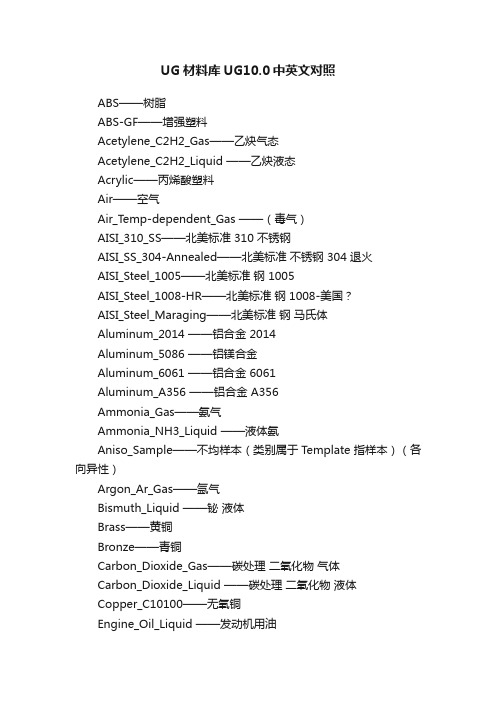
UG材料库UG10.0中英文对照ABS——树脂ABS-GF——增强塑料Acetylene_C2H2_Gas——乙炔气态Acetylene_C2H2_Liquid ——乙炔液态Acrylic——丙烯酸塑料Air——空气Air_Temp-dependent_Gas ——(毒气)AISI_310_SS——北美标准 310 不锈钢AISI_SS_304-Annealed——北美标准不锈钢 304 退火AISI_Steel_1005——北美标准钢 1005AISI_Steel_1008-HR——北美标准钢 1008-美国?AISI_Steel_Maraging——北美标准钢马氏体Aluminum_2014 ——铝合金 2014Aluminum_5086 ——铝镁合金Aluminum_6061 ——铝合金 6061Aluminum_A356 ——铝合金 A356Ammonia_Gas——氨气Ammonia_NH3_Liquid ——液体氨Aniso_Sample——不均样本(类别属于 Template 指样本)(各向异性)Argon_Ar_Gas——氩气Bismuth_Liquid ——铋液体Brass——黄铜Bronze——青铜Carbon_Dioxide_Gas——碳处理二氧化物气体Carbon_Dioxide_Liquid ——碳处理二氧化物液体Copper_C10100——无氧铜Engine_Oil_Liquid ——发动机用油Epoxy——环氧树脂Ethylene_Glycol_Liquid ——乙烯乙二醇液体Freon_Liquid_R12——氟利昂 R12Glycerin_Liquid ——甘油Helium_Gas——氦气Hydrogen_Gas_H2——氢气Inconel_718-Aged ——铬镍铁合金 718 老标准Iron_40 —— 40 铁Iron_60 —— 60 铁Iron_Cast_G25——铸铁 G25Iron_Cast_G40——铸铁 G40Iron_Cast_G60——铸铁 G60Iron_Malleable ——可锻造铁Iron_Nodular ——球状石墨铸铁Isobutane_(R600a)_Gas——异丁烷气体Isobutane_(R600a)_Liq——异丁烷液体Lead_Liquid——液态铅Magnesium_Cast——铸造镁Mercury_Liquid ——水银Methane_CH4_Gas——甲烷气体Methanol_CH3(OH) ——甲醇液体Nak(22-78)_LiquidNaK(45-55)_Liquid——Nitrogen_Gas_N2——氮气Nylon——尼龙Ortho_Sample ——正色样本Ortho_Sample_Legacy——正色样本复数Ortho_Sample_W_Damping ——正色样本 W 阻尼Oxygen_Gas_O2——氧气PbBi(45-55)_Liquid——液态 PbBiPolycarbonate——聚碳酸酯Polycarbonate-GF——聚碳酸酯Polyethylene ——聚乙烯Polypropylene ——聚丙烯Polypropylene-GF——聚丙烯Polyurethene-Hard ——聚丙烯硬Polyurethene-Soft ——聚丙烯软Potassium_Liquid——液体钾Propane_C3H8_Gas——丙烷PVC——聚氯乙烯R134a_C2H2F4_Gas——四氟乙烷气态R134a_C2H2F4_Liquid——四氟乙烷液态S/Steel_PH15-5——一种不锈钢SMC——片状模塑料Sodium_Liquid——金属钠液态Steel-Rolled——镀金钢Steel——钢Sulfur_Dioxide_Liquid ——二氧化硫液体Titanium-Annealed ——退火钛Titanium_Alloy ——钛合金Titanium_Ti-6Al-4V ——某种钛合金Tungsten——金属钨Waspaloy——美国牌号的高温合金钢water ——水Water_saturated_Liquid ——饱和的水Water_vapour_Gas——水蒸汽Manten ——蔓藤。
hm_abaqus中文版资料

AltairHyperworks10.0Hypermesh与Abaqus的接口帮助文档中文版29中文资料optistruct指南文档(35)碰撞关键字(控制文件)中文版(20)Hypermesh与abaqus接口文档(12)Hypermesh与dyna接口文档(18)Hypermesh指南文档(35)ANSA(网格划分部分)(20)疲劳Ncode7.0(design life) (25)更多软件和法规,范例资料,慢慢翻译积累资料声明资料翻译费时费力,希望能让您的学习过程感到省时,给力!我本来不想发行电子版的,传到网上可能会被复制,粘贴,so easy的事情,我就得“被雷锋”了。
个人建议:或许您能够偶尔得到一份只言片语的资料,或者是某个方面的资料,但是如果您想得到更多更全的学习资料,建议你亲自联系我们。
比如,做碰撞的,想学习NVH,学习流体,学习疲劳,电磁场等;做汽车行业的,想看看其他行业(如航空,重工,电子产品,生命科学)主打软件是什么,比如高薪的航空工业疲劳分析工程师,一汽,泛亚,上海大众,上汽,北汽疲劳工程师主要应用Ncode(疲劳软件的鼻祖,功能最全,最强大);还有船舶行业patran软件,很多经典资料(像Patran PCL Workshop Notes)还木有中文版。
在一个或两个方面特别精通的基础上,再对其它方面熟悉,或许您会更受业内欢迎。
如果您需要更多,关于Hyperworks,ansa,MSC.patran,nastran,dytran;LS-dyna,abaqus,adams,ansys,madymo,MoldFlow,MARC, Ncode,Optistruct帮助文档中文版。
请联系:QQ:290538306邮箱:zzuzhangyanhua@很多资料国内代理公司不公开或者根本没有。
到我们这里,某些已有中文版,暂时没有的资料可以从无到有,欢迎团购,更欢迎个人。
市面上的CAE书籍,一些理论加几个简单例子,性价比不实惠设置HyperMesh中的Abaqus分析- HM-4300此文档中,我们将学习:•加载Abaqus模板和模型。
HA13166H中文资料

HA13166HMultiple Voltage Regulator for Car AudioREJ03F0224-0100Rev.1.00Jan 16, 2007 DescriptionThe HA13166H is a compact multiple voltage regulator for car audio system. The outputs of this IC output consist of regulated 5.7 V output for a microcontroller, regulated 3.3 V output for a digital signal processor, regulated 8 V output for CD driver, regulated 9.0 V output for audio control, regulated 10 V output for illuminations and regulated 5 V output, VCC-dependent output for external output and VCC-dependent output for remote-ANT.FunctionsGeneral• ACC power monitor circuit is built-in.• Low saturation output (PNP output) used for audio output.• Adjustable voltage for illumination output by changing an external resistor.Protections• Output current limit circuit to avoid device destruction caused by shorted output, etc.• High surge input protector against VCC and ACC.• Built in a thermal shutdown circuit to prevent against the thermal destruction.Pin Description and Equivalent CircuitPin Description and Equivalent Circuit (cont.)Timing ChartBlock DiagramAbsolute Maximum Ratings(Ta = 25°C)Item Symbol Rating Unit NoteOperating power supply voltage Vcc 18 V DC supply voltage Vcc(DC) 26 V 1 Peak voltage Vcc(PEAK) 50 V2Power dissipation Pd 36 W 3Junction temperature Tj 150 °C Operating temperature Topr –40 to +85 °C Storage temperatureTstg–55 to +125°CNotes: Recommended power supply voltage range 10 to 16 V. 1. Applied time is less than 30 s. 2. Surge pulse as input. 3. Ta = 25°C. : Permissible power dissipation when using a heat sink of infinite area. Refer to the deratingcurves below.Electrical Characteristics(unless otherwise noted, Vcc = 13.2 V, Ta = 25°C)Item SymbolMin Typ Max Unit Test ConditionStandby current IST — 400 600 µA ACC = 0 V, CTRL = 0 V CTRL L level (STBY mode) VCL 0 — 1.0 V CTRL M level (CD OFF mode) VCM 2.0 — 3.0 V CTRL H level (CD ON mode) VCH 4.0 — – V ANT CTRL L level (ANT OFF mode) VACL 0 — 2.0 V ANT CTRL H level (ANT ON mode) VACH 3.0 — – VOutput voltage Vo1 5.4 5.7 6.0 V Io1 = 80 mAVoltage regulation ∆Vo11 — 10 50 mV Vcc = 10 to 16 V, Io1 = 80 mA Load regulation∆Vo12 — 50 100 mV Io1 = 0 to 80 mA Minimum I/O voltage differential∆Vo13 — 1.0 1.5 V Io1 = 80 mAOutput current capacity Io1 100250 — mA Vo1 ≥ 5.4 VVDD OUTRipple rejection ratioSVR1 50 60 — dB f = 100 Hz, Io1 = 80 mA Output voltage Vo2 7.6 8.0 8.4 V Io2 = 1.0 AVoltage regulation ∆Vo21 — 40 100 mV Vcc = 10 to 16V, Io2 = 1.0 A Load regulation∆Vo22 — 70 150 mV Io2 = 10m to 1.0 A Minimum I/O voltage differential∆Vo23 — 1.0 1.5 V Io2 = 1.0 AOutput current capacity Io2 1.3 2.0 — A Vo2 ≥ 7.6 VCD OUTRipple rejection ratioSVR2 45 50 — dB f = 100 Hz, Io2 = 1.0 A Output voltage Vo3 8.5 9.0 9.5 V Io3 = 400 mAVoltage regulation ∆Vo31 — 30 90 mV Vcc = 10 to 16 V, Io3 = 400 mA Load regulation∆Vo32 — 100 200 mV Io3 = 10 to 400 mA Minimum I/O voltage differential∆Vo33 — 0.4 0.9 V Io3 = 400 mAOutput current capacity Io3 500850 — mA Vo3 ≥ 8.5 VAUDIO OUTRipple rejection ratioSVR3 40 50 — dB f = 100 Hz, Io3 = 400 mA Output voltage Vo4 9.5 10.0 10.5V Io4 = 400 mAVoltage regulation ∆Vo41 — 40 100 mV Vcc = 12.5 to 16 V, Io4 = 400 mA Load regulation∆Vo42 — 50 100 mV Io4 = 10 to 400 mA Minimum I/O voltage differential∆Vo43 — 1.0 1.5 V Io4 = 400 mAOutput current capacity Io4 500900 — mA Vo4 ≥ 9.5 VILM OUTRipple rejection ratioSVR4 32 40 — dB f = 100 Hz, Io4 = 400 mA Output voltage Vo5 3.1 3.3 3.5 V Io5 = 120 mAVoltage regulation ∆Vo51 — 10 50 mV Vcc = 10 to 16 V, Io5 = 120 mA Load regulation∆Vo52 — 50 100 mV Io5 = 0 to 120 mA Output current capacityIo5 150300 — mA Vo5 ≥ 3.1 VDSP OUTRipple rejection ratio SVR5 50 60 — dB f = 100 Hz, Io5 = 120 mA Differential I/O voltage ∆Vo61 — 1.0 1.5 V Io6 = 300 mA Load regulation∆Vo62 — 350 600 mV Io6 = 10 to 300 mA EXT OUT Output current capacity Io6 300500 — mA Vo6 ≥ 11.7 V Differential I/O voltage ∆Vo71 — 1.0 1.5 V Io7 = 300 mALoad regulation ∆Vo72 — 350 600 mV Io7 = 10 to 300 mA ANT OUTOutput current capacityIo7300500—mAVo7 ≥ 11.7 VElectrical Characteristics (cont.)(unless otherwise noted, Vcc = 13.2 V, Ta = 25°C)Item Symbol Min Typ Max Unit Test ConditionOutput voltage Vo8 4.6 5.0 5.4 V Io8 = 80 mA, VDD = no load SW5V OUT Output current capacity Io8 100300 — mA Vo8 ≥ 4.6 VOutput voltageVo9 4.6 5.0 5.4 V Io9 = 40 mA, VDD = no load Output current capacity Io9100300—mAVo9 ≥ 4.6 VRise threshold voltage VTHH9 2.6 2.8 3.0 V ACC OUTHysteresis range∆VTH9 0.2 0.3 0.4 VEvaluation CircuitMain CharacteristicsPackage Dimensions RENESAS SALES OFFICESRefer to "/en/network" for the latest and detailed information.Renesas Technology America, Inc.450 Holger Way, San Jose, CA 95134-1368, U.S.ATel: <1> (408) 382-7500, Fax: <1> (408) 382-7501Renesas Technology Europe LimitedDukes Meadow, Millboard Road, Bourne End, Buckinghamshire, SL8 5FH, U.K.Tel: <44> (1628) 585-100, Fax: <44> (1628) 585-900Renesas Technology (Shanghai) Co., Ltd.Unit 204, 205, AZIACenter, No.1233 Lujiazui Ring Rd, Pudong District, Shanghai, China 200120Tel: <86> (21) 5877-1818, Fax: <86> (21) 6887-7898Renesas Technology Hong Kong Ltd.7th Floor, North Tower, World Finance Centre, Harbour City, 1 Canton Road, Tsimshatsui, Kowloon, Hong KongTel: <852> 2265-6688, Fax: <852> 2730-6071Renesas Technology Taiwan Co., Ltd.10th Floor, No.99, Fushing North Road, Taipei, TaiwanTel: <886> (2) 2715-2888, Fax: <886> (2) 2713-2999Renesas Technology Singapore Pte. Ltd.1 Harbour Front Avenue, #06-10, Keppel Bay Tower, Singapore 098632Tel: <65> 6213-0200, Fax: <65> 6278-8001Renesas Technology Korea Co., Ltd.Kukje Center Bldg. 18th Fl., 191, 2-ka, Hangang-ro, Yongsan-ku, Seoul 140-702, KoreaTel: <82> (2) 796-3115, Fax: <82> (2) 796-2145Renesas Technology Malaysia Sdn. BhdUnit 906, Block B, Menara Amcorp, Amcorp Trade Centre, No.18, Jalan Persiaran Barat, 46050 Petaling Jaya, Selangor Darul Ehsan, MalaysiaTel: <603> 7955-9390, Fax: <603> 7955-9510。
HM3669中文资料
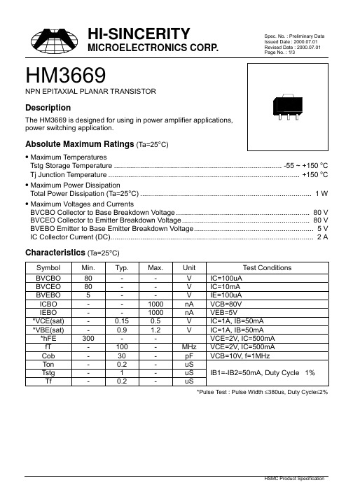
Page No. : 1/3HM3669NPN EPITAXIAL PLANAR TRANSISTORDescriptionThe HM3669 is designed for using in power amplifier applications,power switching application.Absolute Maximum Ratings (Ta=25°C)• Maximum TemperaturesTstg Storage Temperature.................................................................................... -55 ~ +150 °C Tj Junction Temperature................................................................................................ +150 °C • Maximum Power DissipationTotal Power Dissipation (Ta=25°C)...................................................................................... 1 W • Maximum Voltages and CurrentsBVCBO Collector to Base Breakdown Voltage................................................................... 80 V BVCEO Collector to Emitter Breakdown Voltage................................................................ 80 V BVEBO Emitter to Base Emitter Breakdown Voltage............................................................ 5 V IC Collector Current (DC)...................................................................................................... 2 A Characteristics (Ta=25°C)Symbol Min.Typ.Max.Unit Test ConditionsBVCBO80--V IC=100uABVCEO80--V IC=10mABVEBO5--V IE=100uAICBO--1000nA VCB=80VIEBO--1000nA VEB=5V*VCE(sat)-0.150.5V IC=1A, IB=50mA*VBE(sat)-0.9 1.2V IC=1A, IB=50mA*hFE300--VCE=2V, IC=500mAfT-100-MHz VCE=2V, IC=500mACob-30-pF VCB=10V, f=1MHzTon-0.2-uSIB1=-IB2=50mA, Duty Cycle 1% Tstg-1-uSTf-0.2-uS*Pulse Test : Pulse Width ≤380us, Duty Cycle≤2%Page No. : 2/3 Characteristics CurvePage No. : 3/3 SOT-89 DimensionImportant Notice:• All rights are reserved. Reproduction in whole or in part is prohibited without the prior written approval of HSMC.• HSMC reserves the right to make changes to its products without notice.•HSMC semiconductor products are not warranted to be suitable for use in Life-Support Applications, or systems.• HSMC assumes no liability for any consequence of customer product design, infringement of patents, or application assistance. Head Office And Factory :•Head Office (Hi-Sincerity Microelectronics Corp.) : 10F.,No. 61, Sec. 2, Chung-Shan N. Rd. Taipei Taiwan R.O.C.Tel : 886-2-25212056 Fax : 886-2-25632712, 25368454•Factory 1 : No. 38, Kuang Fu S. Rd., Fu-Kou Hsin-Chu Industrial Park Hsin-Chu Taiwan. R.O.CTel : 886-3-5983621~5 Fax : 886-3-5982931•Factory 2 : No. 17-1, Ta-Tung Rd., Fu-Kou Hsin-Chu Industrial Park Hsin-Chu Taiwan. R.O.CTel : 886-3-5977061 Fax : 886-3-5979220。
HyperMesh PAMCRASH Solver Interface 10.0 Tutorials
HyperMesh 10.0 Tutorials PAM-CRASH 2G Solver InterfaceHyperWorks is a division ofAltair Engineering Contact InformationWeb site FTP site Address: or or /ftpLogin: ftpPassword: <your e-mail address>Location Telephone e-mailNorth America 248.614.2425 hwsupport@China 86.21.6117.1666 support@France 33.1.4133.0992 francesupport@Germany 49.7031.6208.22 hwsupport@altair.deIndia 91.80.6629.4500support@1800.425.0234 (toll free)Italy 39.800.905.595 support@altairengineering.itJapan 81.3.5396.2881 support@altairjp.co.jpKorea 82.31.716.4321 support@altair.co.krScandinavia 46.46.286.2052 support@altair.seUnited Kingdom 44.1926.468.600 support@Brazil 55.11.3884.0414 br_support@.brAustralia 64.9.413.7981 anzsupport@New Zealand 64.9.413.7981 anzsupport@The following countries have distributors for Altair Engineering:Asia Pacific: Indonesia, Malaysia, Singapore, Taiwan, ThailandEurope: Czech Republic, Hungary, Poland, Romania, Spain, Turkey.©2009 Altair Engineering, Inc. All rights reserved. No part of this publication may be reproduced, transmitted, transcribed, stored in a retrieval system, or translated to another language without the written permission of Altair Engineering, Inc. To obtain this permission, write to the attention Altair Engineering legal department at: 1820 E. Big Beaver, Troy, Michigan, USA, or call +1-248-614-2400.Trademark and Registered Trademark AcknowledgmentsListed below are Altair® HyperWorks® applications. Copyright© Altair Engineering Inc., All Rights Reserved for: HyperMesh® 1990-2009; HyperView® 1999-2009; OptiStruct® 1996-2009; RADIOSS® 1986-2009; HyperCrash™ 2001-2009; HyperStudy® 1999-2009; HyperGraph® 1995-2009; MotionView®1993-2009; MotionSolve® 2002-2009; TextView™ 1996-2009; MediaView™ 1999-2009; HyperForm® 1998-2009; HyperXtrude®1999-2009; HyperView Player® 2001-2009; Process Manager™ 2003-2009; Data Manager™ 2005-2009; Assembler™ 2005-2009; FEModel™ 2004-2009; BatchMesher™ 2003-2009; Templex™ 1990-2009; Manufacturing Solutions™ 2005-2009; HyperDieDynamics™ 2007-2009; HyperMath™ 2007-2009; ScriptView™ 2007-2009.In addition to HyperWorks® trademarks noted above, GridWorks™, PBS™ Gridworks®, PBS™ Professional®, PBS™ and Portable Batch System® are trademarks of ALTAIR ENGINEERING INC., as is patent # 6,859,792. All are protected under U.S. and international laws and treaties. All other marks are the property of their respective owners.HyperMesh 10.0 Tutorials - PAM-CRASH 2G Solver Interfacei Altair Engineering Proprietary Information of Altair Engineering HyperMesh 10.0 Tutorials - PAM-CRASH 2G Solver Interface ........................................................................................................................................... 1Using the PAM-CRASH Interface in HyperMesh - HM-4700Using the PAM-CRASH Interface in HyperMesh - HM-4700For this tutorial it is recommended that you complete the introductory tutorial, Getting Started with HyperMesh - HM-1000.This tutorial introduces the HyperMesh interface to PAM-CRASH 2G. The following exercises are included:·Load a prepared HyperMesh file·Select the Pam-Crash 2G user profile·Create control cards·Assign element types·Define materials·Define HyperMesh groups: sliding interface·Define a rigid wall·Creating boundary conditions·Create time histories·Creating a function·Creating a sensor card·Exporting a Pam-Crash 2G data deck from HyperMeshAll files referenced in the HyperMesh tutorials are located in the <install_directory>\tutorials\hm directory. For detailed instructions on how to locate the installation directory at your site, see Finding the Installation Directory <install_directory>, or contact your system administrator.ExerciseStep 1: Load a prepared HyperMesh fileA prepared model with elements and nodes is included in the <install_directory>\tutorials\hm \directory. The file name of the example is rail-dyna.hm. This is the basic example on which the tutorial is based.1.From the File drop down menu, select Open… or click the Open .hm file icon.2.Browse to the file <installation_directory>\tutorials\hm\interfaces\lsdyna/rail-dyna.hm.3.Click Open.1HyperMesh 10.0 Tutorials - PAM-CRASH 2G Solver Interface Altair EngineeringProprietary Information of Altair EngineeringStep 2: Select the PAM-CRASH 2G user profileTo use HyperMesh with a specific solver, the solver user profile must be loaded. Upon opening, HyperMesh prompts you to select a user profile. Select the Pam-Crash 2G profile.Selecting the Pamcrash 2G user profile sets the FE input reader to Pamcrash 2G and loads the Pamcrash 2G 2006 FE output template. It also loads a Pamcrash 2G Utility Menu with numerous tools specific to this interface. The graphical user interface is tailored to Pamcrash 2G users.Steps 3-6: Create Control Cards for PAM-CRASH 2GThis section explains how to create control cards for the CONTROL SECTION of the PAM-CRASH 2G deck. Note The settings of the control cards influence the default values for defining materials. No PAM-CRASH 2G deck can be executed without error if control cards are undefined.Step 3: Define the title card1.From the Setup drop down menu, select Create and then select Control Cards.2.Scroll through the options to select the Title sub-panel.3.In the TITLE / field enter This is my first PAM-CRASH example.4.Click return.Step 4: Define the output control cards1.Click Output Control Parameters.2.In the TIOD field, enter the value0.005.3.In the PIOD field, enter the value 0.005.4.Click return.5.Click End of Run Definition.6.In the TIME field, enter the value 0.06.7.Click return.Altair Engineering HyperMesh 10.0 Tutorials - PAM-CRASH 2G Solver Interface2Proprietary Information of Altair EngineeringStep 5: Define the file optional keyword1.Scroll through the options to select the File Name sub-panel.2.In the File field, enter rail-dyna.hm.3.Click return.Step 6: Define the time step optional keyword1.Scroll through the options to select the Timestep Control Parameters sub-panel.2.At the bottom of the card image click the SHELL_TIMESTEP_OPT check box.3. Set the Shell Criteria to LARGE (default) from the pop-up menu.4.Click the switch below Thickness Term and set BEND (default) from the pop-up menu.5.Click return twice to close the panels.Step 7: Assign Element Types for PAM-CRASH 2GDepending on the analysis requirement, the HyperMesh basic element type can be changed. For example, a quad4 can be a SHELL or a MEMBR element. The tria3 element can be a TRIA_C, SHELL, or MEMBR element. The tetra4, the penta6, and the hexa8 elements define the SOLID elements of PAM-CRASH. Properties can be added for the selected element type by using the control cards.1.From the Mesh drop down menu, select Assign and select Element Type.2.Select the 2D & 3D sub-panel and click quad4 = and select SHELL from the pop-up menu.3.Click elems and select all from the extended entity selection menu.4.Click update.5.Click return to to close the panel.Steps 8-10: Define material and /PART cards for PAM-CRASH 2G Before proceeding with the tutorial we will rename the component tmp.1.In the Model Browser, expand the components folder.2.Right-click on the component tmp and click rename.The field becomes open for editing.3.Enter topbottom and click Enter.Step 9: Define a Material Type 1023HyperMesh 10.0 Tutorials - PAM-CRASH 2G Solver Interface Altair EngineeringProprietary Information of Altair Engineering1.Select the Materials collectors icon from the toolbar or click the Materials drop down menu and selectCreate.2.Click mat name = and enter new mat.3.Click card image = and select MAT_2D from the pop-up menu.Note The template provides MAT_1D, MAT_2D, and MAT_3D dictionaries. Material types from 200 to 230 are defined with MAT_1D. Materials types from 100 to 151 are defined with MAT_2D.Material types from 1 to 41 are defined with MAT_3D. To switch the material type, use thecard previewer.4.Click create/edit.5.Click the switch below Material Type and select Type 102 from the pop-up menu.6.In the density field, enter the value7.85e-9.Note You can use the TAB or SHIFT TAB key on the keyboard to go to the next or previous edit field.7.In the Name field, enter This is a new material.8.In the E field, enter the value 20000.9.In the Yield field, enter the value 250.10.In the v field, enter the value 0.3.11.Click return.Step 10: Assign material and thickness to side and topbottom collectors1.From the Collector drop down menu, select Edit and then select Component.2.Click on comps. Place a checkmark next to the side and topbottom components and click select.3.Click on card image = and select Part_2D (note that a new thickness= field now appears).4.Click on material = and select new mat.5.Click update/edit.6. In the h field, enter the value 2.5 as the thickness.7.Click return twice to access the main menu.Steps 11-14: Define HyperMesh Groups: Sliding Interface for PAM-CRASH 2GThis section describes how to define a self contacting sliding interface. A second interface is defined only for tutorial purposes.The procedure below explains how to define a type 36 self contacting sliding interface.Altair Engineering HyperMesh 10.0 Tutorials - PAM-CRASH 2G Solver Interface4Proprietary Information of Altair EngineeringStep 11: Define the group1.From the BCs drop down menu, select Create and select Interfaces.2.Click name = and enter self_impact.3.Click type = and select CNTAC36 from the pop-up menu.Note that the card image is updated simultaneously.4.Click interface color and select a color.5.Click create/edit.6.In the SLFACM field,enter 1.0.7.In the TITLE field,enter the name This is the selfimpact interface.8.Click return.Step 12: Add the slave components1.Select the add sub-panel.2.Click name = twice and select self_impact.3.Click the switch below slave: and select comps from the pop-up menu.4.Click comps and select side and topbottom.5.Click update.6.Click return.If update is not clicked, no changes to the previous definition are made. No changes are made to the graphics window, because the master and slave component list is not displayed.Note If you edit this interface with the card previewer, the master and slave set and component definition are not shown; however, they are still defined in the add sub-panel.Step 13: Define an additional contactThis procedure explains how to define a type 34 master slave (element - node) contact.1.From the BCs drop down menu, select Create and select interfaces.2.Click name = and enter masterslave.3.Click type = and select CNTAC34 from the pop-up menu.Note that the card image is updated simultaneously.4.Click interface color and select a color.5.Click create/edit.5HyperMesh 10.0 Tutorials - PAM-CRASH 2G Solver Interface Altair EngineeringProprietary Information of Altair EngineeringAltair Engineering HyperMesh 10.0 Tutorials - PAM-CRASH 2G Solver Interface6Proprietary Information of Altair Engineering 6.In the SLFACM field, enter 1.0.7.Click return .Step 14: Add the master elements and slave nodes1.Select the add sub-panel.2.Click the switch below master: and select entity from the pop-up menu.3.Click the switch below slave: and select entity from the pop-up menu.4.After master:, click elems to highlight the box with the blue input cursor.5.Select two elements on the model.6.Click the upper right green add button.7.After slave:, click nodes to highlight the box with the blue input cursor.8.Select two nodes on the model.9.Click the lower right green add button.10.Click return to close the panel.You should now see the master elements (elements with x) and the slave nodes displayed on the model.Steps 15-19: Define a Rigid Wall for PAM-CRASH 2GThis section explains how to define a type 4 infinite rigid wall with a base node at -1.00, 0.0, 0.0.Step 15: Create a base node for the rigid wall1.From the Geometry drop down menu, select Create and select Nodes.2.Select the type in sub-panel.3.In the X= field, enter the value–1.0.4.In the Y= field, enter the value 0.0.5.In the Z= field, enter the value0.0.6.Click create node.7.Click return to close the panel.Step 16: Create and define the rigid wall card1.From the BCs drop down menu, select Create and select Rigid Walls.2.Click name = and enter rwall1.3.Click type = and select RWALL from the pop-up menu.4.Click rgdwall color and select a color.5.Click size = and enter the value 100.This specifies the display size of the rigid wall.6.Click create.Step 17: Define rigid wall geometry1.Select the geom sub-panel.2.Click name = twice and select rwall1.3.Click the switch after shape: and select plane from the pop-up menu.4.Click the toggle after shape: and select infinite.5.Click the switch below normal vector: and select vector.6.Click the second switch and select x-axis from the pop-up menu.7.Click base node to highlight the box with the blue input cursor.8.Select the created node in the graphics area.You may need to click f on the permanent menu to see the node.9.Click update.The rigid wall is now shown in the graphics area.Step 18: Add slave nodes for the rigid wall7HyperMesh 10.0 Tutorials - PAM-CRASH 2G Solver Interface Altair EngineeringProprietary Information of Altair Engineering1.Select the add sub-panel.2.Click the switch below slaves: and choose nodes from the pop-up menu.3.Click the yellow nodes button twice and select by id from the extended entity selection menu.4.Enter the value 1-21 and press Enter.Note that 21 nodes at the interface of the rail and the rigid wall are highlighted. Also note that one of the nodes was not selected.5.Click the node that was not highlighted.orClick the yellow node button and enter the value 1012 in the id field.6.Click add.The selected nodes are now set as slaves.Step 19: Add motion to the rigid wall1.Select the motion sub-panel.2.Click the switch below name = and select components from the pop-up menu.3.Click x comp = and enter the value 1.0.4.Click the switch below type of motion: and select velocity from the pop-up menu.5.Click update.6.Click return to close the panel.Step 20: Define attributes in the card previewer1.Select the card edit icon .2.Click groups and select rwall1.3.Click select.4.Click edit.5.Click the switch below Friction type flag and select no sliding from the pop-up menu.6.Click the switch below Rigid Wall Descriptor – Plane Type and select Type 4 from the pop-up menu.Note The card previewer of the rigid wall changed according to the definitions made. Now it is possible to define the mass and the initial velocity for moving rigid wall with finite mass.7.In the mRW field, enter 1.8.In the VINIT field, enter 2000.0.9.Click return twice to close the panels.Steps 21-22: Create boundary conditions for PAM-CRASH 2GThis section explains how to create model boundary conditions.Step 21: Create a load collector1.Select the load collectors icon from the toolbar, or click the Collectors drop down menu andselect Create and select Load Collectors.2.Select the create sub-panel.3.Click loadcol name = and enter boundary conditions.4.Click the switch and select no card image from the pop-up menu.5.Click color and select a color from the pop-up menu.6.Click create.7.Click return to close the panel.The footer bar now displays boundary conditions as the current loadcol.Step 22: Specify the constraints1.From the BCs drop down menu, select Create and select Constraints.2.Click Load Type = and choose BOUNC from the pop-up menu.All constraints that are now created will be displacement boundary conditions.3.Click nodes and select by id from the pop-up menu.4.Enter the value 990-1011and click Enter.5.Click size = and enter the value 10.6.Click create.The constraints are now added to the nodes.7.Click return to close the panel.Steps 23-26: Create Time Histories for PAM-CRASH 2GFor PAM-CRASH 2G, time histories may be defined for nodes, elements, and local coordinate systems. For this exercise, you will only create time histories for some nodes and elements. The operation is the same for any type of time history that is created.Step 23: Create a node time history card1.In the Model Browser, expand the LoadCollector folder.2.Right-click on Boundary Conditions and select Hide.The display of loads is now off.3.From the Setup drop down menu, select Create and select Output Blocks.4.Click name = and enter node_thp.5.Click the switch and select nodes from the pop-up menu.e the mouse to select a few nodes in the graphics area.7.Click create.The time history for nodes is now created.Step 24: Create an element time history card1.Click name = and enter elem_thp.2.Click the switch and select elems from the pop-up menu.e the mouse to select a few elements in the graphics area.4.Click create.Step 25: Review time histories entities1.Click review.2.Select elem_thp.The entities associated with this time history are highlighted.3.Click return to close the panel.Step 26: View the time history card image1.From the Setup drop down menu, select Card Edit and then select Output Block.2.Click outputblocks.3.Select elem_thp.4.Click select.5.Click edit.The time history card is displayed as it will look in the output.6.Click return twice to close the panel.Step 27: Create a functionThis section describes how to generate curves, which corresponds to the function cards /FUNCT in PAM-CRASH2G. This curve should serve as a function for a logical sensor switching on and off. At time=0, the sensor is on, at time=0.01 the sensor is switched off.1.From the XY Plots drop down menu, select Curve Editor.2.Click the New... button.3.In the Name field, enter Curve1 and click proceed.4.In the Curve List, highlight Curve1.5.In the table below the Curve List, enter the following values in each column, for three rows of data:·In the x = field, type 0, 0.01, 0.1·In the y = field, type {1, 0, 0}6.Click Update.7.Click Close.Step 28: Create a sensor cardSensors are implemented as properties in HyperMesh. In this example we refer to the curve defined in the preceding Help topic.1.From the Analysis page, select safety and then select sensors.2.Click name = and enter sensor.3.Click card image = and select SENSOR from the pop-up menu.4.Click create/edit.5.In the TITLE field, enter This is a logical function sensor.6.Click the switch below Sensor type and select logical function switch from the pop-up menu.7.Click LCS twice and select curve1.8.Click return twice to close the panels.Step 29: Exporting a PAM-CRASH 2G data deck from HyperMeshThis section explains how to generate a PAM-CRASH 2G input deck from HyperMesh.1.From the File drop down menu, click Export.2.In the file: field, enter rail.pc.rail.pc is the PAM-CRASH2G file you will create.3.Check to ensure that the template = field shows the pamcrash2g/pam2g2006 file.4.Click Export.HyperMesh writes the deck. A message in the footer bar will indicate when the process is completed.5.Click Close.。
HyperWorks中柔性体的生成

HyperWorks生成多体动力学柔性体方法柔性体生成方法•本教程将介绍HyperWorks中柔性体的生成,包含MV所需的柔性体文件(H3D文件),ADAMS软件所需的柔性体文件(mnf文件),以及建立多柔性体模型的注意事项。
•内容:•使用MV生成柔性体文件方法•使用HM10生成柔性体文件方法•柔性体建模注意事项专业词汇•HW-HyperWorks•HM-HyperMesh•OS-OpiStruct•MV-MotionView•MS-MotionSolve•CMS-模态综合法使用MV生成柔性体文件方法•步骤如下:•一)在HyperMesh中只保留网格、材料属性(注意材料密度单位应该是kg/mm^3 ,例如铁的密度应为7.8e-6kg/mm^3)和单元属性卡片,然后output为fem,bdf,或nas文件;•二)使用MotionView中flextools菜单下的flex prep工具(右图),选择所需文件并设置参数。
右图中的interface node是指定柔性体文件连接的节点id号。
如果节点号连续,如有8个节点,节点号从1开始,则写为1:8。
如果节点号不连续,就用+,如2+13+34等。
三)点击ok即可生成MotionView的柔性体h3d文件使用MV 生成柔性体文件方法(续)•Flex prep 工具详细说明:•使用OS 得出柔性体文件•指定interface node•选择一个柔性体原始文件•保存生成柔性体H3D 文件路径•柔性体中是否显示stress 结果•柔性体中是否显示strain 结果•单位设置(推荐默认单位)•调用HM 生成RBE2单元使用MV生成柔性体文件方法(续)•四)假如需要生成mnf文件,则再进行下面的操作•生成h3d文件后,将h3d转化为mnf文件,使用上图的flex prep工具,选择translation of flexbodyfiles和转化的方法(见右图)选项,然后选择已经生成的h3d文件,save一个新的mnf文件即可产生新的mnf文件。
Hypermesh教程、资料汇总
Hypermesh教程、资料汇总基础类我学习hypermesh的经验HYPERMESH菜单解释1hypermesh常见英文解释hypermesh初学者常见英文解释HYPERMESH的一些常见问题的解答hypermesh ppthypermesh 练习教材及入门材料HyperMesh入门实例HyperMesh从入门到精通(教材)——整理前Hypermesh从入门到精通——(整理后)HyperMesh从入门到精通(配套光盘)与经典练习HyperMesh 8.0 basic training(中文)HYPERMESH入门指南hypermesh教程(有hm7.0基础的、实例和论文)几何清理hypermesh 几何清理hypermesh 基础教程hm8.0教程英文版Hyper works 9.0培训资料hyper mesh 教程(5.0 day1 &day2)两天搞定hypermesh(5.0的)收集的hypermesh资料HyperMesh常用的快捷键、键盘操作和鼠标操作HyperMesh常用的快捷键、键盘操作和鼠标操作Hypermesh快捷键Hypermesh\鼠标操作hypermesh快捷键HyperMesh8.0系列教程Hypermesh的中文教程8.0Hypermesh8.0资料(中英文混编)hypermesh8.0 实用教程(中文版)Hypermesh 8.0 Training pdf 原厂资料+model files Hypermesh 8.0的使用手册图文并茂的hypermesh8.0 教程Hypermesh 8.0 day1 and day2(ppt)hyperwork7.0 培训教程hypermesh9.0 培训资料(day1&day2)HyperMesh之几何导入与处理hyperworks9.0_traininghypermesh7.0基础培训中文版(day1&day2)hypermesh7.0基础培训中文版2Hyperstudy 7.0 教程hyperworks7.0培训教程Hypermesh中文基础培训Hypermesh7.0中文基础培训hypermesh 7.0基础培训指南(英文)HyperMesh教程下载(基础培训)Hyperworks全套培训教程(6.0的)Hypermesh入门教程(6.0中文的day1&day2)HyperMesh讲义(6.0的)hypermesh中文版6.0教程Hypermesh6.0中文基础培训hypermesh6.0的经典学习资料hypermesh入门教程hypermesh的技巧:commandFEA online 的hypermesh教程ppt基础的学习hypermeshhyperwork中文经典教程hypermesh的一些资料高级教程类hypermesh高级教程HyperMesh高级教程hyperworks高级培训教程hypermesh高级教程Hm8.0AdvancedTraining总结类Hypermesh 总结hypermesh学习心得hypermesh网格划分总结-转视频类HyperMesh几何清理-moviehypermesh8.0实体网格划分视频HyperMesh视频教程hypermesh8.0autodelete_and_automesh视频一个HYPERMESH实例HyPerMesh经典网格操作HyperMesh的抽取中面功能视频教学Hypermesh ---Solids_and_Solid_Meshing视频教程hypermesh automesh视频hyperworks视频学习HyperMesh抽取中面视频HYPERMESH 薄壁零件划分视频HyperGraph 3D功能视频资料hypermesh等截面圆柱相贯网格划分操作视频优化教程hyperworks optistruct 车架优化HYPERWORKS 优化设计官方培训资料hypermesh与ABAQUS教程hypermesh与ABAQUS的强强联合Hypermesh8.0与Aba接口,CAE分析必备HyperMesh6.0和Abaqus的接口实例Hypermesh与其它有限元软件的接口及单位abaqus与hypermesh 应用的一个教程HyperMesh6.0和Abaqus的接口实例与ansys接口教程hypermesh怎么导入ansyshypermash和ansys的接口用HYPERMESH进行前处理后如何导入ANSYS进行后处理HyperMesh 与Ls-Dyna接口教程HyperMesh 与Ls-Dyna 联合应用HyperMesh和LS-Dyna做车身或者结构件的crash分析基于HyperMesh-Ls-Dyna的手机跌落模拟仿真的解析安装教程及问题汇总hypermesh8.0安装方法HyperWorks8.0图文安装说明hypermesh8.0安装方法HyperWorks8.0完全安装中文帮助HyperWorks8.0安装问题(解决办法)HYPERWORKS.V8.0安装说明中文安装帮助HyperWorks8完全安装中文帮助ANSYS 、HYPERMESH 等软件的安装方法及接口问题hypermesh安装(7.0)实例教程hypermesh分网实例hypermesh六面体划分示例螺栓预紧结构用Hypermesh做接触实例hypermesh几篇论文hypermesh在汽车开发中的应用基于Hypermesh的皮卡车架分析基于Hypermesh的皮卡车架模态分析基于HYPERMESH的有限元前置优化设计hypermesh下载HyperMESH 10.0 官方下载Altair Hyperworks 9.0 下载Hyperwork 8.0下载地址Hyperworks 7.0。
Hypermesh10.0-与LS-dyna-接口帮助文档中文版
Altair软件Hyperworks10.0Hypermesh与LS-dyna接口全部帮助文档中文版中文资料optistruct指南文档(付费)碰撞关键字(控制文件)中文版(免费)Hypermesh与abaqus接口文档(免费) Hypermesh与dyna接口文档(免费)Hypermesh指南文档(免费)ANSA(网格划分部分)(免费)疲劳Ncode7.0(design life) (免费)更多软件和法规,范例资料,慢慢翻译积累提供cae软件,法规相关翻译,培训个人资料声明资料翻译费时费力,希望能让您的学习过程感到省时,给力!我本来不想发行电子版的,传到网上可能会被复制,粘贴,so easy的事情,我就得 “被雷锋”了。
个人建议:或许您能够偶尔得到一份只言片语的资料,或者是某个方面的资料,但是如果您想得到更多更全的学习资料,建议你亲自联系我们。
比如,做碰撞的,想学习NVH,学习流体,学习疲劳,电磁场等;做汽车行业的,想看看其他行业(如航空,重工,电子产品,生命科学)主打软件是什么,比如高薪的航空工业疲劳分析工程师,一汽,泛亚,上海大众,上汽,北汽疲劳工程师主要应用Ncode(疲劳软件的鼻祖,功能最全,最强大);还有船舶行业patran软件,很多经典资料(像Patran PCL Workshop Notes)还木有中文版。
在一个或两个方面特别精通的基础上,再对其它方面熟悉,或许您会更受业内欢迎。
如果您需要更多,关于Hyperworks,ansa,MSC.patran,nastran,dytran;LS-dyna,abaqus,adams,ansys,madymo,MoldFlow,MARC, Ncode,Optistruct很多资料国内代理公司不公开或者根本没有。
到我们这里,某些已有中文版,暂时没有的资料可以从无到有,欢迎团购,更欢迎个人。
市面上的CAE书籍,一些理论加几个简单例子,性价比不实惠检查干涉,创建joint连接,检查最小时步-HM-4500开始学习此指导之前,我们建议先完成介绍指导,Getting Started with HyperMesh - HM-1000. 此指导解释了在不同碰撞求解器中的通用操作技巧。
HEVC学习必备---HM的使用
HM使用最好附带下载HM的reference software manual即参考软件手册,这个手册的主要内容包括HM的下载地址和使用方法,更重要的是,里面包含了对配置文件各个参数的详细解释,可以说是使用HM的必备手册。
最后,就是真正地编译HM工程了。
从运行环境来讲,既可以在linux系统下使用makefile对HM进行编译,也可以在windows系统下使用IDE如VS对HM进行编译。
我个人是用VS2008作为开发环境,因此,这里也只介绍使用VS编译HM。
关于linux下如何进行,请参看前面提到的参看软件手册吧。
打开下载下来的HM文件夹,工程存放在build目录下,工程名为HM_VC9(对VS2008而言)。
右击“Solution'HM_VC9'(7projects)”->“build solution”。
正常的话,等待片刻所有工程都能得到正确的编译,并最终在HM文件夹下生成bin目录,在目录xxx\bin\vc9\Win32\Debug下,最终会生成两个可执行文件,TAppEncoder.exe和TAppDecoder.exe,分别问编码和解码的可执行文件,到了这一步,表明你之前的步骤都是正确的。
接下来就能进入到编解码器的使用当中来了。
先说编码器的使用:右击“TAppEncoder”->“Set as Startup Project”,接着,再次右击“TAppEncoder”->“Properties”->“Configuration Properties”->“Debugging”,在弹出的右窗口中有这么两行需要关注:“Command Arguments“和“Working Directory”。
前者用于输入运行时的命令参数,后者用于指定工程的工作目录。
先说工作目录,将其设置为xxx\bin\vc9\Win32\Debug,即上一步中编译生成的可执行文件的绝对路径。
HM中文说明书1
目录第一节系统说明1 引言2 电解液3 电解槽4 电解液子系统(1)KOH泵(2)KOH贮罐(3)换热器(4)KOH过滤器(5)流量开关(6)KOH温度传感器(7)KOH液位计5 给水子系统(1)给水(2)给水水质监测器(3)给水泵(4)给水控制6 气体控制和调节子系统(1)压力变送器(2)产气速率(3)预压(4)备用(5)压力释放(6)背压调节器(7)差压调节器(8)安全阀(9)排空阀(10)冷凝器和捕集器(11)纸型隔膜(12)氮气冲洗7 氢气干燥(1)干燥器(2)干燥器阀8 冷却及冷凝器冷却水子系统(1)温度调节阀(2)冷凝器冷却水及其控制9 系统安全(1)氧中氢监测器(2)电流监测器(3)氢检测器(4)停车报警10 电力和工艺控制子系统(1)DC电源(2)可编程控制器(3)工艺控制及程序(4)干燥器程序11 数据显示和工艺监控(1)触摸屏显示(2)发光二极管监控第二节发生器安装1 系统类别2 发生器安装3 设备连接(1)给水(2)冷却水(3)冷凝器冷却水(4)氢、氧排气阀(5)产品气输送(6)电力(7)氮气吹洗4电源的电连接5 外部报警连接第三节发生器运行1 前言2 初次启动3 启动模式4 运行模式5 备用模式6 常规运行7 压力释放8 停车第四节维护和校验规程1 前言2 电解液(1)电解液混和(2)电解液注入(3)电解液检查(4)电解液排放3 电解槽检查(1)外观检查(2)内部检查(3)再紧固规程4 纸型隔板更换5 渗透渗漏检查6 KOH过滤器更换7 给水过滤器更换8 KOH泵检查9 阀门和调节器维修和校验(1)电磁阀(2)差压调节器(3)背压调节器(4)止回阀和安全阀10 氧中氢监测器维修及校验(1)流量控制器(2)过滤器罐(3)温度传感器11 系统试压12 差压变速器13 KOH流量开关检查14 给水泵起动及冲洗15 给水检测器检查16 干燥器维修(1)孔板维修(2)止回阀维修(3)分子筛更换(4)气体过滤器更换17 温度调节阀检查第五节排除故障指南附录A目录系统组件图1 框架组件图号;A-12 电解槽组件图号;A-23 给水和冷却水组件图号;A-34 气体控制组件图号;A-45 控制箱组件图号;A-56 干燥器组件图号;A-6附录B目录系统图1 HM管道图图号;M141562 HM-C1D2发生器接线图图号;ES-M-009第一节系统说明1 引言HM系统的基本设备配置包括两块,即氢气发生器和电源。
- 1、下载文档前请自行甄别文档内容的完整性,平台不提供额外的编辑、内容补充、找答案等附加服务。
- 2、"仅部分预览"的文档,不可在线预览部分如存在完整性等问题,可反馈申请退款(可完整预览的文档不适用该条件!)。
- 3、如文档侵犯您的权益,请联系客服反馈,我们会尽快为您处理(人工客服工作时间:9:00-18:30)。
单元, 几何点, 线, 曲面, 连接 椭球体, 多体联接, 多体平面, 传感器
部件, 多体, 装配体 载荷, 约束方程 无 (材料和属性不包含其它实体但仍然作为collectors来对待) 坐标系 向量 梁 截 梁截面 面
Copyright © 2009 Altair Engineering, Inc. Proprietary and Confidential. All rights reserved.
模型组织: Collectors
• 一个实体只能属于一个给定类型的collector • 例如:一个单元只能放在一个component中 • 可以创建多个同一类型的collector • 同一个collector中的实体具有相同颜色 • 可以按照用户的需要进行组织
Component 4 Component 3
Bold “Current Include”
Copyright © 2009 Altair Engineering, Inc. Proprietary and Confidential. All rights reserved.
模型组织: Tools
• Panels面板
• Collectors – 创建新 collectors • Model Browser – 为各种实体类型设置当前collector
Copyright © 2009 Altair Engineering, Inc. Proprietary and Confidential. All rights reserved.
模型组织: Collectors
• • • • Hypermesh中模型是通过“collectors”组织的 Collectors分为很多类 大部分hypermesh实体必须被放置在某个collector中 每种类型collector放置指定类型的一种或几种实体
实体 节点 单元
• 有限元模型
• 节点 • 临时节点(用一个小圆圈表示) • 单元
临时节点
Copyright © 2009 Altair Engineering, Inc. Proprietary and Confidential. All rights reserved.
模型组织: HyperMesh 实体类型
4) 怎么操作: 定义操作过程的 参数
5) 操作: 执行操作
Copyright © 2009 Altair Engineering, Inc. Proprietary and Confidential. All rights reserved.
模型组织: HyperMesh 实体类型
• 几何
• • • • • 点 曲线 曲面 体 连接(用于建立连接) 曲线 点 曲面
•通过在屏幕上抓取一个点并拖拽鼠标实现旋转 •相对于光标位置和屏幕中心进行旋转 •平移模型
Collector 类型 可放置的实体类型:
Component部件 Multibody多体
Assembly组件 Load Collector载荷集 Material材料 Property属性 System Collector坐标系集 Vector Collector向量集 Beam Section Collector梁截面集
Copyright © 2009 Altair Engineering, Inc. Proprietary and Confidential. All rights reserved.
Do-it-yourself
Exercise: Reorganizing a Bumper Model
• Page 29
面板: 总体布局
• 一些子面板以列方式组织
• 每一列表示一种不同的操作方法 • 从上到下完成列的操作 • 例如: surface edit : trim with surfs/plane 子面板
1) 操做什么: 选择一个子面板 进行操作
2) 操作方法: 在适当的列进 行操作
3) 操作对象是 什么: 选择操作对象
• 有限元载荷
• 载荷(约束,力,压力等) • 约束方程(节点间的数学关系) 力
压力
• 接触
约束 • 组(定义实体间的接触) • 接触面(定义接触中作为主面或从节点的一系列实体)
接触面
Copyright © 2009 Altair Engineering, Inc. Proprietary and Confidential. All rights reserved.
模型组织: Collectors
• Model browser模型浏览器
• • • • 通过树状的层级结构查看collectors 和assemblies 创建、删除、重命名 collectors 编辑 collector 属性 将collectors 组织成assemblies 在 Collector上右 • 通过鼠标左键拖放
• Organize –将实体放到不同的collector中
• Rename – 重命名已有 collector • Reorder • Collectors 会在选择列表中以一定的顺序显示 • Reorder用来改变 collectors 出现的顺序 • Delete – 删除 collectors
Tags
Titles
Copyright © 2009 Altair Engineering, Inc. Proprietary and Confidential. All rights reserved.
模型组织: HyperMesh 实体类型
• Morphing(网格变形)
• Handles –控制柄:用于在变形过程中控制模型形状 • Domains – 域:用于把模型分成若干区域 (针对基于domain的morphing) • Morph volume – 变形体积块:通过体积块的变形控制体积块内网格的变形(针 对基于体积块的变形) • Morph constraints –变形约束:控制变形过程中的节点运动 • Symmetries – 对称:强制模型在变形过程中的变形对称 • Shapes –形状变量: 变形保存后的模型状态,可在后续过程中提取使用 Handles
• 新创建的collector被自动设置为当前collector
• Model browser可在模型树中用右键切换当前collector. • Include Browser 用来切换当前 include. • Organize面板用于将实体移入另一个collector
Bold “Current Collector”
Copyright © 2009 Altair Engineering, Inc. Proprietary and Confidential. All rights reserved.
Altair HyperWorks 10.0
HyperMesh介绍
Day 1
Insert Instructor Name Here
模型组织: HyperMesh 实体类型
• 绘图
• curve曲线(X-Y 数据) • plot绘图窗口(带坐标轴的曲线显示)
• 输出请求
• Loadsteps载荷工况(载荷集的组合
• Output blocks输出块 (特定实体的分析输出 请求)
有一条曲线的绘图
• 标签
• Titles曲线标题 (给曲线加个标题) • Tags实体标贴 (给实体指定一个名字)
模型组织: HyperMesh 实体类型
• 多体
• 椭球体 (定义一个刚体形状) • 多体平面 (定义一个刚体形状) • 多体连接(定义两个刚体之间的连接)
• 安全性分析
• 传感器(定义一个事件启动开关) • 控制体积 (定义气囊)
Copyright © 2009 Altair Engineering, Inc. Proprietary and Confidential. All rights reserved.
Morph Volume
Symmetries
Domains
Copyright © 2009 Altair Engineering, Inc. Proprietary and Confidential. All rights reserved.
模型组织: HyperMesh 实体类型
• 优化 • Designvars – 优化变量:优化过程中可变的量 (例如:厚度) • Optiresponses – 优化响应:优化过程被测量的值 (例如:冯米赛斯应力) • Objectives – 目标:取最大(最小)值的响应 。例如:重量 • Dobjrefs – 目标参照:用于定义minmax/maxmin优化的目标参考响应 (如: 最小化最 大冯米赛斯应力) • Opticonstraints – 优化限制 (例如:冯米赛斯应力< 屈服应力) • Optidscreens – 约束过滤以减小计算时间 • Dvprels – 设计变量与属性关联 • Desvarlinks – 设计变量关联 • Dequations – 通过计算得到的测量值 • Optitableentrs – 常数列表 • Opticontrols – 优化算法控制参数 • DDVals –用于设计变量定义的离散值
Copyright © 2009 Altair Engineering, Inc. Proprietary and Confidential. All rights reserved.
Chapter 1: HyperMesh介绍
新手上路 打开与保存文件 面板操作 模型组织 显示控制
Copyright © 2009 Altair Engineering, Inc. Proprietary and Confidential. All rights reserved.