英格索兰空气压缩机Modbus RS485通讯说明
英格索兰空压机说明书
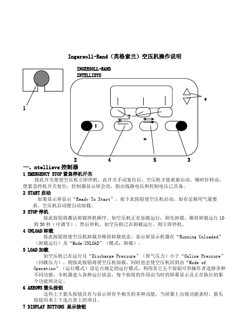
Ingersoll-Rand (英格索兰)空压机操作说明一、ntellisvs 控制器 1 EMERGENCY STOP 紧急停机开关按此开关便使空压机立即停机。
此开关手动复位后,空压机才能重新启动。
顺时针转动,使紧急停机开关复位,控制器显示屏会亮,指出线路电压和控制电压已具备。
2 START 启动如果显示屏显示“Ready To Start ”,按下此按钮使空压机启动。
如有足够用气量要求,空压机启动便自动加载。
3 STOP 停机按此按钮将激活卸载停机顺序。
如空压机正在加载运行,则先卸载,维持卸载运行10到30秒(可调节),然后停机。
如空压机已在卸载运行,则立即停机。
4 UNLOAD 卸载按此按钮将使空压机卸载并维持卸载状态。
显示屏显示机器在“Running Unloaded ”(卸载运行)及“Mode:UNLOAD ”(模式:卸载)。
5 LOAD 加载如空压机已在运行且“Discharge Pressure ”(排气压力)小于“Online Pressure ”(回跳压力),则按此按钮将使空压机加载。
同时也会使空压机回到由“Mode ofOperation ”(运行模式)设定点规定的运行模式。
利用其它五个按钮可供操作者选择多种不同功能,令机器进入各种运行状态。
每个按钮的作用由当时的屏幕显示及正在执行的那个功能所决定。
6 ARROWS 箭头按钮这些上下箭头按钮具有与显示屏有半相关的多种功能,当屏幕上出现功能表时,箭头按钮用来上下选点表上的项目。
7 DISPLAY BUTTONS 显示按钮6INGERSOLL-RAND显示屏幕下面三个按钮的功能是改变紧接在它们上面的屏幕最下一行的显示字符,并由这些字符定义。
二、CURRENT STATUS 当前状态CURRENT STATUS屏幕是控制器的“正常”显示状态。
CURRENT STATUS参数项Package Discharge Temperature 机组排气温度Airend Discharge Temperature 主机排气温度Injected Temperature 喷油温度Sump Pressure 分离前压力Separator Pressure Drop 油分离器压降Coolant Filter 油过滤器Invet Vacuum 进气负压Inlet Filter 进气过滤器Total Hour 总运行小时Loaded Hour 加载小时%Load Modulation 加载调节百分比Software Title and Version 软件名称及版本如30秒内不按任何按钮,控制器便自动从其它屏幕回到CURRENT STATUS屏幕。
英格索兰空压机使用说明书

当管网的气压上升到某一定值时,相应的空压机会按照预定的次序自动延时停机。通常关机延时的时间设置为4-8秒。
4.设置运行轮换时间(按时间长度周期切换)
用户可将空压机的运行次序,设置具有定时切换的功能,以求各台空压机总运行时间相同,通常设置为20分钟。此功能必须在有空余机器的前提下才能实现。
SIEMENS EM231模拟量输入模块
断路器
热继电器
中间继电器
接触器
电机
变压器
三位选择开关(包括手动、停止、自动)
二位选择开关(在手动控制方式下可以启动和停止空压机-维护用)
电源指示灯
故障指示灯
运行指示灯
急停、复位按钮
压力变送器
超高压压力开关
二、工作原理及操作方法
控制方式具备手动、停止和自动3种工作状态(由三位选择开关控制)。
*本机中设置了两个报警:1、压力传感器故障报警,2、超压报警。当用户屏幕右侧正中出现闪烁的感叹号时,表明有报警,按两次ESC键返回“显示报警”菜单,查看具体报警内容。当出现报警时机组强制停机,需排除问题后按F1重新启动机器。
1.设置空压机的运行次序
D1、D2、D3、Dx分别代表了空压机组的启动次序,用户可以根据实际情况设置为1、3、2等各种不同启动次序。但同一台机器不要重复被选取2次或以上(出厂设置启动顺序为1、2、3);同时此设置可进行投入机组的设置,可将故障机组排除运行之列,将希望投入运行的机器按顺序设置好以后其他均以0设置。
在自动控制方式下,二位选择开关无效。空压机根据用户的实际用气量相应投入运行、轮换工作。F1启动、F2停止。
在TD400文本显示器上的设置。
初设密码(4109),下面为文本显示器的功能菜单(在正常显示屏幕下按ESC键出现):
MODBUS实例485通讯解析

用RS485端口控制TVF2000使用说明:一、硬件连接:1.RS485/RS485:(1)终端设备:将J2用终端方式短接;(2)非终端设备:将J2用非终端方式短接;(3)A、B、AGND对接;(4)如果使用屏蔽线,SCR对接。
2.RS485/RS232(PC机):(1)用RS485/RS232转换器;(2)PC机串口与转换器RS232口连接;(3)TVF2000的CN1与转换器的RS485口的A、B、AGND连接。
二、用MODBUS与TVF2000通讯(RTU方式):1.TVF2000键盘设置:a)键盘菜单设置说明:i.1001=10:外端子1用通讯控制;ii.5005=2:标准MODBUS通讯方式;iii.5201=1-247:从机号(缺省=1);iv.5202=5:通讯速度为9600bps(缺省=5);v.5203=0:无效验(缺省=0);vi.其它=缺省值;b)键盘具体操作:i.9952 = 1:参数初始化;ii.1001 = 10;iii.5005 = 2;这样设置后,就可以与TVF2000通讯了。
2.TVF2000使用的MODBUS命令:a)读存储寄存器:03命令;b)写单个寄存器:06命令;c)写多个寄存器:16命令;3.MODBUS单寄存器写入命令说明(其它说明见附录):a)主机发送:i.[地址]:从机地址1-247;ii.[命令]:06,单寄存器写入命令;iii.[寄存器地址_H]:寄存器地址高8位;iv.[寄存器地址_L]:寄存器地址低8位;v.[数据_H]:写入数据高8位;vi.[数据_L]:写入数据低8位;vii.[CRC_H]:CRC效验高8位;viii.[CRC_L]:CRC效验低8位;b)从机返回(正常):i.[地址]:从机地址1-247(相同地址);ii.[命令]:06,单寄存器写入命令;iii.[寄存器地址H]:寄存器地址高8位;iv.[寄存器地址L]:寄存器地址低8位;v.[数据_H]:写入数据高8位;vi.[数据_L]:写入数据低8位;vii.[CRC_H]:CRC效验高8位;viii.[CRC_L]:CRC效验低8位;c)通讯具体操作(菜单1102=7为例):i.主机发送:[01][06][04][4E][00][07][CRC_H][CRC_L];ii.从机返回(正常):[01][06][04][4E][00][07][CRC_H][CRC_L];4.用通讯命令设置菜单值(调速前必须设置):i.1102=7;外部1有效;ii.1103=8;由串行通讯给定;iii.0002=初始频率;如果不设置,为菜单1104的值;iv.0001=0x06;命令寄存器:0001;v.0001=0x0f;vi.0001=0x2f;启动;vii.0001=0x6f;到达设定频率;5.用通讯命令调速(给定寄存器1:0002):i.0002=0-20000;调速:0对应1104的值,20000对应1105的值;ii.通过03命令读取状态寄存器(0004)的值;iii.通过03命令读取保持寄存器(0005、0006)的值;iv.用通讯命令停车:0001 = 0x06;6.7.给定寄存器1:0002(MODBUS为40002)说明如下:i. 输出频率与给定值成正比例;ii. 输出频率=(0002的值)*(1105的值)/20000;8.状态寄存器:0004(MODBUS为40004)说明如下:9.保持寄存器:0005(MODBUS为40005):实际输出频率(单位:Hz);10.保持寄存器:0006(MODBUS为40006):实际输出电流(单位:0.1A);11.状态寄存器、保持寄存器均为只读;12.如果想保存通讯设置,必须用键盘设置菜单1607=1。
英格索兰空压机使用说明书
当管网的气压上升到某一定值时,相应的空压机会按照预定的次序自动延时停机。通常关机延时的时间设置为4-8秒。
4.设置运行轮换时间(按时间长度周期切换)
用户可将空压机的运行次序,设置具有定时切换的功能,以求各台空压机总运行时间相同,通常设置为20分钟。此功能必须在有空余机器的前提下才能实现。
可编程控制器(PLC):是用于工业控制的微处理器。它通过编入控制程序达到输入和输出的特定控制关系。它具有稳定性好、控制功能强和便于维修等特点。选用SIEMENS S7-200 PLC
SIEMENS TD400操作面板:可以在面板上修改需要设定的参数,机器根据设定的参数运行;及进行参数查询。
SIEMENS EM231模拟量输入模块
注意:手动状态仅作为试机、检修、紧急补压.手动状态下只受控于超高压保护压力开关,当超高压开关动作后需手动复位超高压复位按钮方可(超高压并无报警指示灯,系统超高压后电路断开并自锁,机器无法启动,故需手动复位).请试机、检修时慎重操作。
在自动控制方式下,二位选择开关无效。空压机根据用户的实际用气量相应投入运行、轮换工作。F1启动、F2停止。
断路器
热继电器
中间继电器
接触器
电机
变压器
三位选择开关(包括手动、停止、自动)
二位选择开关(在手动控制方式下可以启动和停止空压机-维护用)
电源指示灯
故障指示灯
运行指示灯
急停、复位按钮
压力变送器
超高压压力开关
二、工作原理及操作方法
控制方式具备手动、停止和自动3种工作状态(由三位选择开关控制)。
手动控制时,先将控制柜上三位选择开关打到手动状态,方可用二位选择开关手动控制相应机器启停。
英格索兰空压机说明手册

英格索兰空压机说明手册 Ting Bao was revised on January 6, 20021I n g e r s o l l -R a n d (英格索兰)空压机操作说明12453一、ntellisvs 控制器 1EMERGENCYSTOP 紧急停机开关按此开关便使空压机立即停机。
此开关手动复位后,空压机才能重新启动。
顺时针转动,使紧急停机开关复位,控制器显示屏会亮,指出线路电压和控制电压已具备。
2START 启动如果显示屏显示“ReadyToStart ”,按下此按钮使空压机启动。
如有足够用气量要求,空压机启动便自动加载。
3STOP 停机按此按钮将激活卸载停机顺序。
如空压机正在加载运行,则先卸载,维持卸载运行10到30秒(可调节),然后停机。
如空压机已在卸载运行,则立即停机。
4UNLOAD 卸载按此按钮将使空压机卸载并维持卸载状态。
显示屏显示机器在“RunningUnloaded ”(卸载运行)及“Mode:UNLOAD ”(模式:卸载)。
5LOAD 加载如空压机已在运行且“DischargePressure ”(排气压力)小于“OnlinePressure ”(回跳压力),则按此按钮将使空压机加载。
同时也会使空压机回到由“ModeofOperation ”(运行模式)设定点规定的运行模式。
利用其它五个按钮可供操作者选择多种不同功能,令机器进入各种运行状态。
每个按钮的作用由当时的屏幕显示及正在执行的那个功能所决定。
6ARROWS 箭头按钮这些上下箭头按钮具有与显示屏有半相关的多种功能,当屏幕上出现功能表时,箭头按钮用来上下选点表上的项目。
7DISPLAYBUTTONS 显示按钮显示屏幕下面三个按钮的功能是改变紧接在它们上面的屏幕最下一行的显示字符,并由这些字符定义。
二、CURRENTSTATUS 当前状态CURRENTSTATUS 屏幕是控制器的“正常”显示状态。
CURRENTSTATUS 参数项PackageDischargeTemperature 机组排气温度AirendDischargeTemperature 主机排气温度InjectedTemperature 喷油温度SumpPressure 分离前压力SeparatorPressureDrop 油分离器压降CoolantFilter 油过滤器InvetVacuum 进气负压6INGERSOLL-RAND INTELLISYSInletFilter进气过滤器TotalHour总运行小时LoadedHour加载小时%LoadModulation加载调节百分比SoftwareTitleandVersion软件名称及版本如30秒内不按任何按钮,控制器便自动从其它屏幕回到CURRENTSTATUS屏幕。
Endress+Hauser Proline Promag H 500 Modbus RS485 操

Products Solutions Services操作手册Proline Promag H 500电磁流量计Modbus RS485BA01401D/28/ZH/05.22-00715882112022-08-01自下列版本起生效01.06.zz (设备固件)Proline Promag H 500 Modbus RS485•请将文档妥善保存在安全地方,便于操作或使用设备时查看。
•为了避免出现人员或装置危险,请仔细阅读“基本安全指南”章节,以及针对特定操作步骤的文档中的所有其他安全指南。
•制造商保留修改技术参数的权利,将不预先通知。
Endress+Hauser当地销售中心将为您提供最新文档信息和更新文档资料。
2Endress+HauserProline Promag H 500 Modbus RS485目录Endress+Hauser 3目录1文档信息 (6)1.1文档功能.............................61.2图标................................61.2.1安全图标......................61.2.2电气图标......................61.2.3通信图标......................61.2.4工具图标......................71.2.5特定信息图标...................71.2.6图中的图标.....................71.3文档资料代号.........................81.3.1文档功能......................81.4注册商标.............................82安全指南 (9)2.1人员要求.............................92.2指定用途.............................92.3工作场所安全........................102.4操作安全............................102.5产品安全............................102.6IT 安全.............................102.7设备的IT 安全.......................102.7.1通过硬件写保护实现访问保护......112.7.2访问密码.....................112.7.3通过网页服务器访问.............122.7.4通过服务接口(CDI-RJ45)访问. (12)3产品描述 (13)3.1产品设计............................133.1.1Proline 500(数字)变送器.......133.1.2Proline 500(模拟)变送器. (13)4到货验收和产品标识 (15)4.1到货验收............................154.2产品标识............................154.2.1变送器铭牌....................164.2.2传感器铭牌....................184.2.3测量设备上的图标..............195储存和运输 (20)5.1储存条件............................205.2运输产品............................205.2.1不带起吊吊环的测量仪表.........205.2.2带起吊吊环的测量设备...........215.2.3使用叉车搬运..................215.3包装处置............................216安装 (21)6.1安装要求............................216.1.1安装位置.....................216.1.2环境条件和过程条件要求.........266.1.3特殊安装指南..................276.2安装测量设备........................286.2.1所需工具.....................286.2.2准备测量设备..................286.2.3安装传感器....................286.2.4安装变送器外壳:Proline 500(数字)变送器...................306.2.5安装变送器外壳:Proline 500变送器........................326.2.6旋转变送器外壳:Proline 500.....336.2.7旋转显示模块:Proline 500.......336.3安装后检查..........................347电气连接 (35)7.1电气安全............................357.2接线要求............................357.2.1所需工具.....................357.2.2连接电缆要求..................357.2.3接线端子分配..................397.2.4屏蔽和接地....................397.2.5准备测量设备..................407.2.6准备连接电缆:Proline 500(数字)变送器...................417.2.7准备连接电缆:Proline 500.......417.3连接测量设备:Proline 500(数字)变送器................................437.3.1电缆接线.....................437.3.2连接信号电缆和供电电缆.........487.4连接测量设备:Proline 500.............507.4.1电缆接线.....................507.4.2连接信号电缆和供电电缆.........537.5确保电势平衡........................557.5.1要求.........................557.5.2连接实例:标准应用场合.........557.5.3连接实例:特殊应用场合.........557.6特殊接线指南........................577.6.1接线实例.....................577.7硬件设置............................607.7.1设置设备地址..................607.7.2使用终端电阻..................627.8确保防护等级........................637.9连接后检查..........................648操作方式 (65)8.1操作方式概述........................658.2操作菜单的结构和功能.................668.2.1操作菜单的结构................668.2.2操作方式.....................678.3通过现场显示单元访问操作菜单..........688.3.1操作界面.....................688.3.2菜单视图.....................698.3.3编辑界面.....................718.3.4操作单元.....................738.3.5打开文本菜单..................738.3.6在列表中移动和选择.............75目录Proline Promag H 500 Modbus RS4854Endress+Hauser8.3.7直接查看参数..................758.3.8查询帮助文本..................768.3.9更改参数.....................768.3.10用户角色及访问权限.............778.3.11通过访问密码关闭写保护.........778.3.12打开和关闭键盘锁..............778.4通过网页浏览器访问操作菜单............788.4.1功能范围.....................788.4.2要求.........................788.4.3建立连接.....................808.4.4登录.........................828.4.5用户界面.....................828.4.6关闭网页服务器................838.4.7退出.........................838.5通过调试软件访问操作菜单..............848.5.1连接调试软件..................848.5.2FieldCare .....................878.5.3DeviceCare .. (88)9系统集成 (89)9.1设备描述文件概述.....................899.1.1当前设备版本信息..............899.1.2调试软件.....................899.2与老产品型号的兼容性.................899.3Modbus RS485协议...................909.3.1功能代码.....................909.3.2寄存器信息....................909.3.3响应时间.....................909.3.4数据类型.....................919.3.5字节传输序列..................919.3.6Modbus 数据映射...............9210调试 (94)10.1功能检查............................9410.2启动测量设备........................9410.3通过FieldCare 连接...................9410.4设置显示语言........................9410.5设置测量设备........................9510.5.1设置设备位号..................9610.5.2设置系统单位..................9610.5.3设置通信接口..................9810.5.4显示输入/输出设置..............9910.5.5设置电流输入.................10010.5.6设置状态输入.................10110.5.7设置电流输出.................10110.5.8设置脉冲/频率/开关量输出......10410.5.9设置现场显示单元.............10910.5.10设置小流量切除...............11110.5.11设置空管检测.................11310.5.12设置继电器输出...............11310.5.13设置双脉冲输出...............11510.5.14设置流量阻尼时间.............11610.6高级设置 (119)10.6.1在此参数中输入访问密码。
Endress+Hauser CNGmass 模Bus RS485 压力流量计说明书

Brief Operating InstructionsCNGmassMODBUS RS485Coriolis mass flow measuring systemFor fueling with compressed natural gas (CNG)These Brief Operating Instructions are not intended to replace theOperating Instructions provided in the scope of supply. Detailedinformation is provided in the Operating Instructions and theadditional documentation on the CD-ROM supplied.Depending on the device version, the complete devicedocumentation consists of:•Brief Operating Instructions (this document)•Operating Instructions•Description of Device Functions•Approvals and safety certificates•Safety instructions in accordance with the approvals for the device(e.g. explosion protection, pressure equipment directive etc.)•Additional device-specific informationKA00047D/06/EN/13.1571231247Table of contents CNGmass Table of contents1 Safety instructions. . . . . . . . . . . . . . . . . . . . . . . . . . . . . . . . . . . . . 31.1 Designated use . . . . . . . . . . . . . . . . . . . . . . . . . . . . . . . . . . . . . . . . . . . . . . . . . . . . . . . 31.2 Installation, commissioning and operation . . . . . . . . . . . . . . . . . . . . . . . . . . . . . . . . . . . 31.3 Operational safety . . . . . . . . . . . . . . . . . . . . . . . . . . . . . . . . . . . . . . . . . . . . . . . . . . . . . 31.4 Safety conventions . . . . . . . . . . . . . . . . . . . . . . . . . . . . . . . . . . . . . . . . . . . . . . . . . . . . 52 Installation . . . . . . . . . . . . . . . . . . . . . . . . . . . . . . . . . . . . . . . . . . 52.1 Transporting to the measuring point . . . . . . . . . . . . . . . . . . . . . . . . . . . . . . . . . . . . . . . 52.2 Installation conditions . . . . . . . . . . . . . . . . . . . . . . . . . . . . . . . . . . . . . . . . . . . . . . . . . . 52.3 Post-installation . . . . . . . . . . . . . . . . . . . . . . . . . . . . . . . . . . . . . . . . . . . . . . . . . . . . . . 62.4 Post-installation check . . . . . . . . . . . . . . . . . . . . . . . . . . . . . . . . . . . . . . . . . . . . . . . . . . 63 Wiring. . . . . . . . . . . . . . . . . . . . . . . . . . . . . . . . . . . . . . . . . . . . . . 73.1 Connecting the transmitter . . . . . . . . . . . . . . . . . . . . . . . . . . . . . . . . . . . . . . . . . . . . . . 73.2 Degree of protection . . . . . . . . . . . . . . . . . . . . . . . . . . . . . . . . . . . . . . . . . . . . . . . . . . . 83.3 Post-connection check . . . . . . . . . . . . . . . . . . . . . . . . . . . . . . . . . . . . . . . . . . . . . . . . . 84 Commissioning . . . . . . . . . . . . . . . . . . . . . . . . . . . . . . . . . . . . . . . 94.1 Switching on the measuring device . . . . . . . . . . . . . . . . . . . . . . . . . . . . . . . . . . . . . . . . 94.2 Operation . . . . . . . . . . . . . . . . . . . . . . . . . . . . . . . . . . . . . . . . . . . . . . . . . . . . . . . . . . . 94.3 Verification process . . . . . . . . . . . . . . . . . . . . . . . . . . . . . . . . . . . . . . . . . . . . . . . . . . . 104.4 Setting up custody transfer mode . . . . . . . . . . . . . . . . . . . . . . . . . . . . . . . . . . . . . . . . . 104.5 Disabling custody transfer mode . . . . . . . . . . . . . . . . . . . . . . . . . . . . . . . . . . . . . . . . . 114.6 Troubleshooting . . . . . . . . . . . . . . . . . . . . . . . . . . . . . . . . . . . . . . . . . . . . . . . . . . . . . 11 2Endress+HauserCNGmass Safety instructions 1Safety instructions1.1Designated use•The measuring device described in these Operating Instructions may only be used to measure the mass flow or volume flow of compressed natural gas (CNG).•Any use other than that described here compromises the safety of persons and the entiremeasuring system and is, therefore, not permitted.•The manufacturer is not liable for damage caused by improper or non-designated use.1.2Installation, commissioning and operation•The measuring device must only be installed, connected, commissioned and maintained byqualified and authorized specialists (e.g. electrical technicians) in full compliance with theinstructions in these Brief Operating Instructions, the applicable norms, legal regulations and certificates (depending on the application).•The specialists must have read and understood these Brief Operating Instructions and mustfollow the instructions they contain. If you are unclear on anything in these Brief Operating Instructions, you must read the Operating Instructions (on the CD-ROM). The OperatingInstructions provide detailed information on the measuring device.•The measuring device may only be installed in a de-energized state, free from external loads.•The measuring device may only be modified if such work is expressly permitted in theOperating Instructions (on the CD-ROM).•Repairs may only be performed if a genuine spare parts kit is available and this repair work is expressly permitted.•If performing welding work on the piping, the welding unit may not be grounded by means of the measuring device.1.3Operational safety•The measuring device is designed to meet state-of-the-art safety requirements, has beentested, and left the factory in a condition in which it is safe to operate. Relevant regulationsand European standards have been observed.•The information on the warning signs, nameplates and connection labels must be observed.They contain important data on the permitted operating conditions, the operating range of the device and the material.If the measuring device is not used at atmospheric temperatures, compliance with the relevant boundary conditions in accordance with the device documentation supplied (on theCD-ROM) is mandatory.•The measuring device must be wired in accordance with the wiring diagrams and connection labels. Interconnection must be permitted.•All parts of the measuring device must be included in the potential equalization of the plant.•Cables, certified cable glands and certified dummy plugs must be suitable for the prevailingoperating conditions, such as the temperature range of the process for example. Unusedhousing openings must be sealed with dummy plugs.Endress+Hauser3Safety instructions CNGmass •The measuring device may only be used in conjunction with fluids to which all wetted parts of the measuring device are sufficiently resistant. With regard to special fluids, including fluids used for cleaning, Endress+Hauser will be happy to assist in clarifying the corrosion-resistant properties of wetted materials.However, minor changes in temperature, concentration or in the degree of contamination in the process may result in variations in corrosion resistance.For this reason, Endress+Hauser does not accept any responsibility with regard to thecorrosion resistance of wetted materials in a specific application. The user is responsible forthe choice of suitable wetted materials in the process.•Hazardous areasMeasuring devices for use in hazardous areas are labeled accordingly on the nameplate.Relevant national regulations must be observed when operating the device in hazardous areas.The Ex documentation on the CD-ROM is an integral part of the entire device documentation.The installation regulations, connection data and safety instructions provided in the Exdocumentation must be observed. The symbol and the name on the front page provideinformation on the approval/certification body (e.g 0Europe, 2 USA, 1 Canada,NEPSI). The nameplate also bears the documentation number of this Ex documentation(XA***D/../..).•For measuring systems used in SIL 2 applications, the separate manual on functional safety(on the CD-ROM) must be observed.•Hygienic applicationsMeasuring devices for hygienic applications have their own special labeling. Relevant national regulations must be observed when using these devices.•Pressure instrumentsMeasuring devices for use in systems that need to be monitored are labeled accordingly on the nameplate. Relevant national regulations must be observed when using these devices. Thedocumentation on the CD-ROM for pressure instruments in systems that need to bemonitored is an integral part of the entire device documentation. The installation regulations, connection data and safety instructions provided in the Ex documentation must be observed.•Endress+Hauser will be happy to assist in clarifying any questions on approvals, theirapplication and implementation.4Endress+HauserCNGmass InstallationEndress+Hauser 51.4Safety conventions#Warning! "Warning" indicates an action or procedure which, if not performed correctly, can result in injury or a safety hazard. Comply strictly with the instructions and proceed with care."Caution! "Caution" indicates an action or procedure which, if not performed correctly, can result in incorrect operation or destruction of the device. Comply strictly with the instructions.!Note!"Note" indicates an action or procedure which, if not performed correctly, can have an indirect effect on operation or trigger an unexpected response on the part of the device.2Installation 2.1Transporting to the measuring point•Transport the measuring device to the measuring point in the original packaging.•The covers or caps fitted on the process connections prevent mechanical damage to thesensors during transport and storage. For this reason, do not remove the covers or caps until immediately before installation.2.2Installation conditionsThe measuring device is to be installed in a de-energized state free from outside loads or strain.2.2.1DimensionsFor the dimensions of the measuring device see associated Technical Information on the CD-ROM.2.2.2Inlet and outlet runsWhen mounting, no special precautions need to be taken for fittings which create turbulence (valves, elbows, T-pieces etc.).2.2.3VibrationsThe high oscillation frequency of the measuring tubes ensures that the correct operation of the measuring system is not affected by plant vibrations. Consequently, no special attachmentmeasures are required for the sensors.Installation CNGmass6Endress+Hauser2.3Post-installation2.3.1Turning the transmitter housing2.4Post-installation check •Is the measuring device damaged (visual inspection)?•Does the measuring device correspond to the specifications at the measuring point?•Are the measuring point number and labeling correct (visual inspection)?•Has the correct sensor orientation been selected in terms of type, fluid properties, fluidtemperature?•Does the arrow on the sensor point in the direction of the flow in the pipe?•Is the measuring device protected against rain and sunlight?A0006921The transmitter housing canbe rotated counterclockwisecontinuously up to 360°.1.Loosen the Allensetscrew (1) partially,but do not unscrew itall the way.2.Rotate the transmitterhousing into thedesired position.3.Tighten the Allensetscrew (1).1 = Allen screwCNGmass WiringEndress+Hauser 73Wiring#Warning!Risk of electric shock! Components carry dangerous voltages.•Never mount or wire the measuring device while it is connected to the power supply.•Prior to connecting the power supply, connect the protective ground to the ground terminal on the housing.•Route the power supply and signal cables so they are securely seated.•Seal the cable entries and covers so they are airtight."Caution!Risk of damaging the electronic components!•Connect the power supply in accordance with the connection data on the nameplate.•Connect the signal cable in accordance with the connection data in the Operating Instructions or the Ex documentation on the CD-ROM.In addition, for measuring devices with fieldbus communication:"Caution!Risk of damaging the electronic components!•Observe the cable specification of the fieldbus cable → Operating Instructions on theCD-ROM.•Keep the stripped and twisted lengths of cable shield as short as possible.•Screen and ground the signal lines → Operating Instructions on the CD-ROM.•When using in systems without potential matching → Operating Instructions on theCD-ROM.In addition, for Ex-certified measuring devices:#Warning!When wiring Ex-certified measuring devices, all the safety instructions, wiring diagrams,technical information etc. of the related Ex documentation must be observed→Ex documentation on the CD-ROM.3.1Connecting the transmitterWire the unit using the terminal assignment diagram inside the cover.3.1.1Compact version (transmitter): non-Ex Zone, Ex Zone 1, Class I Div. 1A0013057Transmitter connection:123Signal cable or fieldbus cable Power supply cable Connection diagram inside the connection compartment coverWiring CNGmass8Endress+Hauser3.2Degree of protectionThe devices meet all the requirements for IP 67.After mounting in the field or service work, the following points have to be observed to ensure that IP 67 protection is retained:•Install the measuring device in such a way that the cable entries do not point upwards.•Do not remove the seal from the cable entry.•Remove all unused cable entries and plug them with suitable/certified drain plugs.•Use cable entries and drain plugs with a continuous service temperature range according to the temperature data on the nameplate.3.3Post-connection check •Are cables or the device damaged (visual inspection)?•Does the supply voltage match the information on the nameplate?•Do the cables used comply with the necessary specifications?•Do the mounted cables have adequate strain relief and are they routed securely?•Is the cable type route completely isolated? Without loops and crossovers?•Are all screw terminals firmly tightened?•Are all cable entries installed, firmly tightened and correctly sealed?•Cable routed as a “water trap” in loops?•Are all the housing covers installed and securely tightened?In addition, for measuring devices with fieldbus communication:•Are all the connecting components (T-boxes, junction boxes, connectors etc.) connected with each other correctly?•Has each fieldbus segment been terminated at both ends with a bus terminator?•Has the max. length of the fieldbus cable been observed in accordance with the specifications?•Has the max. length of the spurs been observed in accordance with the specifications?•Is the fieldbus cable fully shielded and correctly grounded?A0007549A0007550Tighten the cable entries correctly.The cables must loop down before they enter the cableentries ("water trap").CNGmass CommissioningEndress+Hauser 94Commissioning 4.1Switching on the measuring deviceOn completion of the installation (successful post-installation check), wiring (successfulpost-connection check) and after making the necessary hardware settings, where applicable, the permitted power supply (see nameplate) can be switched on for the measuring device.The measuring device performs a number of power on self-tests. Normal measuring modecommences as soon as startup completes.!Note!If the startup is not successful, depending on the cause, a corresponding message is displayed in the FieldCare operating program, or the status LED flashes correspondingly.4.2OperationYou have the following option for configuring and commissioning the device:A00069261Configuration/operating program for operating via the service interface FXA291 (e.g. FieldCare)2Operation via MODBUS RS485 process control system3Situation sticker of the various DIP switch positions and their function (explanations of DIP switches 2 and 1s. Operating Instructions)4Operation via device-internal DIP switch (4): If the DIP switch (4) is switched upwards, the device restores thefactory settings of the communication parameters of the MODBUS RS485 (return it afterwards to its original lowerposition).5Operation via device-internal DIP switch (3): If the DIP switch (3) is switched upwards, the device restores thefactory settings of all communication parameters of the MODBUS RS485 (return it afterwards to its original lowerposition).Commissioning CNGmass4.3Verification processThe verification process is regulated by national rules or regulations.4.4Setting up custody transfer modeThe flowmeter must be locked for custody transfer measurement (in this status, no parameters can be changed, i.e. all settings must have been configured first according to the application).For this purpose, the switch 1 are moved to the position shown below (1). You receiveconfirmation from the status LED. Then, fit the cover and have the safety claw sealed by a person authorized to do so (2).A0006929Switch locked10Endress+HauserCNGmass Commissioning4.5Disabling custody transfer modeThe flowmeter can be reset to exit custody transfer mode.To do so, destroy and remove the seal on the safety claw (1). This process may be carried out by authorized personnel only. Open the cover. Return switch 1 to the position shown below (2).You receive confirmation from the status LED.A0006930 Switch unlocked4.6TroubleshootingExceptional states that arise during operation are detected by the flowmeter and corresponding messages are output (see CD-ROM):•Via the MODBUS interface, depending on the setting•Via error messages in the "FieldCare" operating program•Via the status LEDIf multiple messages are pending, the one with the highest priority is output.The message about a status can be assigned to a category as follows:OFF•When the status occurs, no message is generated.Error•The message belongs to the "Errors" category, meaning that the measuring system cannotcontinue measuring operation.Note•The message belongs to the "Notes" category, meaning that the measuring system may be able to continue measuring operation with restrictions.Endress+Hauser11KA00047D/06/EN/13.15 71231247。
英格索兰空压机说明书

Ingersoll-Rand (英格索兰)空压机操作说明一、ntellisvs 控制器 1 EMERGENCY STOP 紧急停机开关按此开关便使空压机立即停机。
此开关手动复位后,空压机才能重新启动。
顺时针转动,使紧急停机开关复位,控制器显示屏会亮,指出线路电压和控制电压已具备。
2 START 启动如果显示屏显示“Ready To Start ”,按下此按钮使空压机启动。
如有足够用气量要求,空压机启动便自动加载。
3 STOP 停机按此按钮将激活卸载停机顺序。
如空压机正在加载运行,则先卸载,维持卸载运行10到30秒(可调节),然后停机。
如空压机已在卸载运行,则立即停机。
4 UNLOAD 卸载按此按钮将使空压机卸载并维持卸载状态。
显示屏显示机器在“Running Unloaded ”(卸载运行)及“Mode:UNLOAD ”(模式:卸载)。
5 LOAD 加载如空压机已在运行且“Discharge Pressure ”(排气压力)小于“Online Pressure ”(回跳压力),则按此按钮将使空压机加载。
同时也会使空压机回到由“Mode ofOperation ”(运行模式)设定点规定的运行模式。
利用其它五个按钮可供操作者选择多种不同功能,令机器进入各种运行状态。
每个按钮的作用由当时的屏幕显示及正在执行的那个功能所决定。
6 ARROWS 箭头按钮这些上下箭头按钮具有与显示屏有半相关的多种功能,当屏幕上出现功能表时,箭头按钮用来上下选点表上的项目。
7 DISPLAY BUTTONS 显示按钮6INGERSOLL-RAND显示屏幕下面三个按钮的功能是改变紧接在它们上面的屏幕最下一行的显示字符,并由这些字符定义。
二、CURRENT STATUS 当前状态CURRENT STATUS屏幕是控制器的“正常”显示状态。
CURRENT STATUS参数项Package Discharge Temperature 机组排气温度Airend Discharge Temperature 主机排气温度Injected Temperature 喷油温度Sump Pressure 分离前压力Separator Pressure Drop 油分离器压降Coolant Filter 油过滤器Invet Vacuum 进气负压Inlet Filter 进气过滤器Total Hour 总运行小时Loaded Hour 加载小时%Load Modulation 加载调节百分比Software Title and Version 软件名称及版本如30秒内不按任何按钮,控制器便自动从其它屏幕回到CURRENT STATUS屏幕。
- 1、下载文档前请自行甄别文档内容的完整性,平台不提供额外的编辑、内容补充、找答案等附加服务。
- 2、"仅部分预览"的文档,不可在线预览部分如存在完整性等问题,可反馈申请退款(可完整预览的文档不适用该条件!)。
- 3、如文档侵犯您的权益,请联系客服反馈,我们会尽快为您处理(人工客服工作时间:9:00-18:30)。
Fieldbus Register Table
Created by NodeFileCreator V2.7 (wv) on 08/06/11 at 14:57:05
FIELDBUS REGISTER TABLE FORMAT RULES
This document lists all of the available registers for the control unit with the abovementioned software. The registers are described using a fixed format. Below is a detailed explanation of the various elements that describe any given register.
Register Name:
This is the name of the register, of which there are four basic types. The first three letters of the register name define the register type and or operation that can be performed. The rest of the name simply describes which particular bit of data is involved.
Available Function:
This defines the type of operation that can be performed. The possible operation types are: “Read data” and “Write data”.
Available Register Range: (always in hexadecimal notation)
This defines the range of the data block the register is part of. It shows the start address of the data block (first register: XXXX) and the end of the data block (last register:YYYY) in the format: XXXX...YYYY. Note: in case the registers are part of a”broadcast” (Adv) data block or are part of the range 4000....5FFF it is always possible to request individual (minimum 1 word) or partial sections of the data block.
Max Register Length: (always in hexadecimal notation)
This defines the maximum data size (number of register) in the overall data block.
Register Address (always in hexadecimal notation)
This defines the actual register address to access the register. In case the FIELDBUS being used is MODBUS RTU the register addresses are exactly the same as "MODBUS holding register addresses". In case of PROFIBUS DP, DEVICENET or other fieldbusses the register adresses are simply numerical identifiers for the various data items.
Register Length: (always in hexadecimal notation)
This defines the fundamental size of the data at the actual register address. It is shown as number of registers (16 bit words) and/or the number of bytes.
Just below the “Register Length” entry there is either a description of the “DATA-TYPE”, “DATA-CONVERSION” or additional comments to describe the structure of the data in more detail.
Descriptions of the various “DATA-TYPE” and “DATA-CONVERSION” items can be found at the bottom of this document.
General terms used in this document
MSB: Most Significant Byte (always the “high order” byte in a 16 bit word => also the “first” byte)
LSB: Least Significant Byte (always the “low order” byte in a 16 bit word => also the “second” byte)
FIELDBUS REGISTER TABLE DATA ACCESS RULES
In principle accessing the data within a data block is only possible when using the full data block size.
Example: the “GetStatus” request for a compressor always produces 3 data words. When requesting the data it is necessary to always request the data as 3 word data block, otherwise the data cannot be read.
The only exceptions to th e rule are “broadcast” (Adv) data blocks (all controller models) and register addresses within the range 4000...5FFF. For those data blocks it is possible to read individual data elements within the data block. Any request for data that falls within the specified data block range is acceptable. Write operations are only possible using the full data block size
Example: a basic sequencer unit broadcast data block which contains 7 individual registers:
- Register F020: AdvAvailableStatus
- Register F021: AdvRunningStatus
- Register F022: AdvLoadedStatus
- Register F023: AdvAlarmStatus
- Register F024: AdvSystemStatus
- Register F025: AdvTargetPressure
- Register F026: AdvSystemPressure
To access data within this data block it is possible to:
- Request each individual register (always 1 word).
- Ask for two subsequent registers (e.g: F021 & F022)
- Ask for any set of registers within the block.
- Ask for the entire data block (F020...F026) with a single request.
The only basic rule is that the data should be requested in such a way that the combination of register start address + number of registers does not exceed the last register address, e.g.: the gateway will not accept a request starting at address F025 with a length of 3 registers.
FIELDBUS REGISTER TABLE
FIELDBUS REGISTER DETAILS。