ph传感器操作手册
PH值传感器
pH 值传感器(型号:PH-BTA或PH-DIN)所有传统的pH 计的实验或示范都可以用我们的pH 值传感器。
使用此传感器更可以自动采集数据、作图表、数据分析等功能。
它的典型应用是:研究家庭常见的酸和碱、酸碱滴定、在化学反应、水族箱内光合作用过程中监测pH 的变化、研究酸雨和缓冲液、河流和湖的水质分析等。
威尼尔(Vernier) 有多本实验手册都有各种使用pH 值传感器的实验。
化学使用威尼尔水质使用威尼尔生物使用威尼尔物理科学威尼尔初中科学使用威尼尔科学使用掌上电脑高级化学使用威尼尔用pH 值传感器采集数据以下是使用pH 值传感器的一般操作流程:数据采集软件此传感器可以与一个界面以及以下的数据采集软件一起使用。
∙Logger Pro 3 这个计算机程序可配合LabQuest、LabPro、或威尼尔动手做!连接使用。
∙Logger Pro 2 这个计算机程序可配合ULI 或Serial Box Interface 使用。
∙Logger Lite 这个计算机程序可配合LabQuest、LabPro、或威尼尔动手做!连接使用。
∙LabQuest App 这个程序是当单独使用LabQuest 时配合使用的。
∙EasyData App 这个TI-83+ 和TI-84+ 计算器应用可配合CBL 2、LabPro、和威尼尔EasyLink 一起使用。
我们建议使用2.0 或更新的版本,您可以从威尼尔的网站,/easy/easydata.html,下载,然后转移到计算器上。
查看威尼尔的网站,/calc/software/index.html,可得到更多有关应用与程序转移指南的信息。
∙DataMate 程序采用DataMate 配合LabPro 或CBL 2 与以下计算器使用:TI-73、TI-83、TI-86、TI-89、和Voyage 200。
在LabPro 和CBL 2 的使用说明书中可看到将程序转移到计算器的指示。
水质PH值传感器(RA0708_R72608_RA0708Y)使用说明书

水质PH值传感器(RA0708_R72608_RA0708Y)使用说明书水质PH值传感器说明书——适用型号:RA0708;RA0708Y;R72608Copyright©Netvox Technology Co.,Ltd.This document contains proprietary technical information which is the property of NETVOX Technology.It shall be maintained in strict confidence and shall not be disclosed to other parties,in whole or in part,without written permission of NETVOX Technology.The specifications are subject to change without prior notice.目录一、声明 (2)二、实物外观 (2)三、简介 (2)四、产品特性 (2)五、操作说明 (2)六、安装方法 (4)七、维护与保养 (6)一、声明在未经大洋事先书面许可的情况下,严禁以任何形式复制、传递、分发和存储本文档中的任何内容。
大洋遵循持续发展的策略。
因此,大洋保留在不预先通知的情况下,对本文档中描述的任何产品进行修改和改进的权利。
在任何情况下,大洋均不对任何数据或收入方面的损失,或任何特殊、偶然、附带或间接损失承担责任,无论该损失由何种原因引起。
本文档的内容按“现状”提供。
除非适用的法律另有规定,否则不对本文档的准确性、可靠性和内容做出任何类型的、明确或默许的保证,其中包括但不限于对适销性和对具体用途的适用性的保证。
大洋保留在不预先通知的情况下随时修订或收回本文档的权利。
二、实物外观图一RA0708外接PH 值Sensor(以实物为准)三、简介RA0708_R72608_RA0708Y 为netvox 基于LoRaWAN 开放协议的ClassA 类型设备,兼容LoRaWAN 协议。
S-PH-01 pH 传感器用户指南说明书

User GuidepH Sensor(S-pH-01)User GuideVersion:V2.11/20©2008-2021Seeed Technology Co.,Ltd.All rights reserved.Content1.Introduction (3)2.Wiring diagrams (4)3.Dimension (5)4.Installation Maintenance and Calibration (6)4.1Installation (6)4.2Maintenance (6)5.Output Signal Conversion (7)6.RS485Modbus Protocol (8)6.1Modbus Protocol (8)6.2Modbus Register (9)6.3Modbus Register Detail Description (12)7.Software Configuration Utility (20)1.IntroductionS-PH-01transmitter measures the PH of solution or semi-solid substrate.The output signal can be RS485and Analog Voltage.The sensor is applicable for industrial,water processing,sewerage system,irrigation,smart agriculture etc.■Can be used for PH measurement ■Output Interface with RS485,Voltage ■High impedance and isolated electrode input ■High accuracy with excellent stability■Reverse power protection and Built-in TVS/ESD protectionSpecificationsOutput Interface Analog Voltage 0-2V(Output resistance ~0ohm)RS485Modbus-RTU Power Supply 3.9-30V/DC 3.9-30V/DC Power Consumption 35mA@24V DC 35mA@24V DCStart-up time <2secondsPH Measurement High impedance and isolated input;Range:0-14PH,Resolution:0.01PH,Accuracy:+/-0.1PH;Can be used for solution or semi-solid substrate Temperature Measurement (Option)Range:-40~80°C,Resolution:0.1°C,Accuracy:+/-0.5°C IP Ratings Electrode:IP68;Transmitter:IP65Operating Temperature -40~85°CInstallationElectrode:3/4"NPT screw threads;Transmitter:Mounting holeCable Length Power and Signal Cable:2meters or Customize;Electrode Cable:5mete rsDimensionElectrode:Width*Diameter 160*30mm;3/4"NPT screw threads Transmitter:140mm*65mm*50mm2.Wiring diagramsType Wiring diagram Analo gVoltag eOutpu tRed (V+):Power Supply +Black (G):Power Supply -Blue (O1):Analog OutputRS485ModbusRed (V+):Power Supply +Black (G):Power Supply -Yellow (T+):RS485+/A/T+White (T-):RS485-/B/T-3.DimensionElectrode DimensionTransmitter Dimension*Note:Do not put the Transmitter into the liquid.4.Installation Maintenance and Calibration4.1InstallationInstallation locations of Electrodes will vary depending on the system design.The key is to monitor a good representative sample of the whole solution directly after introduction of chlorine.The installation location must allow for complete contact of the scrubber liquid with the probes.Some example installation locations for Electrodes include the following:■Outlet of packed tower■Outlet of recycle pump■Pump bypass line■Heat Exchanger bypass line4.2MaintenanceUnder normal conditions,electrodes can last anywhere from several months to several years depending on the type of operation,rate of production,strength of product,and quality of the raw materials used in the process.Because each application is different,there is no average life expectancy.Because the pH responsive glass bulb or flat surface is relatively thin,care should be taken so that the bulb does not become scratched or broken.It is also important that ORP measuring surfaces are not scratched or gouged.The suggestions in this sheet are intended to help avoid these problems.Coating of an electrode’s measuring surface can lead to erroneous readings including shortened span and slow response times.The type of coating determines the type of cleaning technique.Soft Coatings can be removed by vigorous stirring,by use of a squirt bottle or,very carefully,by gently wiping with a soft,clean non-abrasive paper or cloth.Hard Coatings should be chemically removed.The chemical used to remove the coating should be the least harsh chemical that dissolves the coating in1or2minutes and does not attack the electrode’s materials of construction.For example,a calcium carbonate coating might be removed with5%HCl(muriatic acid).Oily or Organic Coatings are best removed with detergents or an appropriate solvent that does not attack the electrode’s materials of construction.For example,isopropyl alcohol might be used but acetone should be avoided if the electrode’s body is made of CPVC.5.Output Signal ConversionPH output conversionOutput Interface Parameters Range Conversion FormulaAnalog Voltage Output0-2V PH range:0-14PH PH=7.00*VOLTAGE.When VOLTAGE=1.0V,thenPH=7.00*1.00=7.RS485 Modbus-RTU PH range:0-14PH PH=(REGISTER VALUE)/100.When REGISTERVALUE=7000,then PH=7000/100=7.00. Temperature range:-40-80°C TEMPERATURE=(REGISTERVALUE)/100.WhenREGISTER VALUE=2013,then TEMPERATURE=2013/100=20.13°C.NOTE:The unit of VOLTAGE is(V)6.RS485Modbus Protocol6.1Modbus ProtocolModbus Protocol is widely used to establish master-slave communication between intelligent devices or sensors.A MODBUS message sent from a master to a slave contains the address of the slave,the function code(e.g.'read register'or'write register'),the data,and a check sum(LRC or CRC).The sensor is RS485interface with Modbus protocol.The default serial communication settings is slave address1,modbus rtu,9600bps,8databits and1stop bit.All communication settings can be changed with modbus command,and take effective after re-power up the sensor.Following modbus function code are supported by sensor.Modbus Function Code0x03:used for reading holdingregister.Modbus Function Code0x04:used for readinginput register.Modbus Function Code0x06:used for writing single holding register.Modbus Function Code0x10:used for writing multiple holdingregister.6.2Modbus RegisterParameters RegisterAddr.(HEX/DEC)DataTypeModbusFunctionCode(DEC)Range and Comments DefaultValueTEMPRATURE0x0000/0INT16RO 3/4-4000-8000for-40.00~80.00°C.N/APH PHVALUE 0x0001/1UINT16RO3/40-1400for0.00-14.00N/ATEMPCOMPENSA TEE N 0x0020/32UINT16R/W3/6/160:ExternalTemperature sensor1:Disabled2:On boardtemperature sensor1PHCALIBRAWAD0 PH calibration point for PH=4.010x0030/48UINT16R/W3/6/16-2000~2000for-2000~2000;Write0xFFFF tocalibrate.N/APHCALIBRAWAD1 PH calibration point for PH=7.000x0031/49UINT16R/W3/6/16-2000~2000for-2000~2000;Write0xFFFF tocalibrate.N/APHCALIBRAWAD2 PH calibration point forPH=10.010x0032/50UINT16R/W3/6/16-2000~2000for-2000~2000;Write0xFFFF tocalibrate.N/ASLAVEADDRESS0x0200/512UINT16R/W3/6/160-2551or12BAUDRATE0x0201/513UINT16R/W 3/6/160-60:1200bps1:2400bps2:4800bps3:9600bps4:19200bps5:38400bps3:9600bpsPROTOCOL0x0202/514UINT16R/W 3/6/160-10:Modbus RTU0:Modbus RTUPARITY0x0203/515UINT16R/W 3/6/160-20:None1:Even2:Odd0:NoneParityDATABITS0x0204/516UINT163/6/1611:8databitsR/W1:8databits STOPBITS 0x0205/517UINT16R/W 3/6/160-10:1stopbit 1:2stopbits0:1stopbitRESPONSEDELAY 0x0206/518UINT16R/W 3/6/160-255for 0-2550milliseconds 0ACTIVEOUTPUTINTE R VAL0x0207/519UINT16R/W3/6/160-255for 0-255seconds.NOTE:UINT16:16bit unsigned integer,INT16:16bit signed integer NOTE:RO:Register is Read Only,R/W:Register is Read/Write NOTE:HEX is Hexadecimal (data with 0x/0X prefix),DEC is Decimal6.3Modbus Register Detail DescriptionTEMPERATURE Data Range-4000-8000For -40.00~80.00°CDefault:N/APower Down Save N/ANote:Temperature value (Binary complement).Example:When REGISTER =0x0702(HEX format),thenVALUE=(0x07*256+0x02)/100=17.94°C.When REGISTER=FF05H (HEX format),then VALUE=((0xFF*256+0x05)-0xFFFF-0x01)/100=(0xFF05-0xFFFF-0x01)/100=-2.51°C.PH VALUE Data Range0-1400for 0-14.00PHDefault:N/APower Down Save N/ANote:PH valueExample:When REGISTER =0x02BC (HEX format),then VALUE=(0x02*256+0xBC)/100=7.00PHTEMPCOMPENSATEEN Data Range0:External Temperature sensor 1:Disabled2:On board temperature sensorDefault:1Power Down Save YESNote:Temperature compensationPHCALIBRAWAD0Data Range-2000~2000Default:N/APower Down Save YESNote:PH calibration AD value for PH=4.01;Immerse the electrode into PH=4.01solution and wait until the reading value being stable,then write 0xFFFF to this register to calibrate.PHCALIBRAWAD1Data Range-2000~2000Default:N/APower Down Save YESNote:PH calibration AD value for PH=7.00;Immerse the electrode into PH=7.00solution and wait until the reading value being stable,then write 0xFFFF to this register to calibrate.Data Range-2000~2000Default:N/APower Down Save YESNote:PH calibration AD value for PH=10.01;Immerse the electrode into PH=10.01solution and wait until the reading value being stable,then write 0xFFFF to this register to calibrate.SLAVEADDRESS ---Modbus Slave Address Data Range0-255Default:1or 12Power Down Save YESNote:Please re-power on the sensor to take effective after set.BAUDRATE ---Serial Comm Baudrate Data Range0-50:1200bps 1:2400bps 2:4800bps 3:9600bps 4:19200bp s5:38400bpsDefault:3Power Down Save YESPROTOCOL ---Serial Comm Protocol Data Range0:Modbus RTUDefault:0Power Down Save YESNote:Please re-power on the sensor to take effective after set.PARITY ---Serial Comm Parity Data Range0-20:NONE 1:EVEN 2:ODDDefault:0Power Down Save YESNote:Please re-power on the sensor to take effective after set.DATABITS ---Serial Comm Databits Data Range11:8databitsDefault:1Power Down Save YESNote:Please re-power on the sensor to take effective after set.STOPBITS ---Serial Comm Stopbits Data Range0-10:1stopbit 1:2stopbitsDefault:0Power Down Save YESNote:Please re-power on the sensor to take effective after set.RESPONSEDELAY ---Serial Comm Response Delay Data Range0-255for 0-2550milliseconds,0for disabledDefault:0Power Down Save YESNote:Sensor will delay a period before response to master request command.Example:When set to 5and receive a request from master device,then sensor will delay 5*10ms=50ms,then response to master.ACTIVEOUTPUTINTERVAL ---Serial Comm Active Output Interval time Data Range0-255for 0-255seconds,0for disabledDefault:0Power Down Save YESNote:Please re-power on the sensor to take effective after set.Note:Sensor will output thedata actively without any master request command.Note:Only ONE sensor should be on RS485network,or there will be data collision and corrupt the data on line.Note:Use key button to restore the serial comm parameters factory value to exit the active output mode.Example:When set to 5then sensor will output the data every 5seconds without any master request command.6.4Modbus Function CodeFor description below,data started with 0X/0x means that it’s in HEX format.6.4.1Function Code 3Protocol ExampleMaster Request:AA 03RRRR NNNN CCCCAA 1byte Slave Address,0-2550x031byte Function Code 3RRRR 2byte Starting Register Addr NNNN 2byte Quantity of Register to read CCCC2byteCRC CHECKSUMSlave Response:AA 03MM VV0VV1VV2VV3…CCCCAA 1byte Slave Address,0-2550x031byte Function Code 3MM 1byte Register Data Byte Count VV0,VV12byte Register Value (High8bits first)VV2,VV32byte Register Value (High8bits first)……Register Value (High8bits first)CCCC2byteCRC CHECKSUMExample:Read register 0x0200-0x0201,that is slave address and baudrate.Master Request:010*********C5B3Slave Response:01030400010003EB F2Slave Addr.1byte0x01Slave Addr.1byte 0x01Function Code 1byte 0x03Starting Register Addr.2byte0x0200Quantity of Register to read 2byte0x0002Checksum2byte0xC5B3Function Code1byte0x03 Register Data ByteCount1byte0x04Register Value: Address 2byte0x00(HIGH8Bits)0x01(LOW8Bits)Register Value: Baudrate 2byte0x00(HIGH8Bits)0x03(LOW8Bits)Checksum2byte0xEBF26.4.2Function Code4Protocol Example Master Request:AA04RRRR NNNN CCCCAA1byte Slave Address,0-2550x041byte Function Code4RRRR2byte Starting Register AddrNNNN2byte Quantity of Register to readCCCC2byte CRC CHECKSUMSlave Response:AA04MM VV0VV1VV2VV3…CCCC AA1byte Slave Address,0-2550x041byte Function Code4MM1byte Register Data Byte CountVV0,VV12byte Register Value(High8bits first)VV2,VV32byte Register Value(High8bits first)……Register Value(High8bits first)CCCC2byte CRC CHECKSUM Example:Read register0x0000-0x0002,that is temperature,PH value.Master Request:01040000000271CBSlave Addr.1byte0x01Function Code1byte0x04Starting RegisterAddr.2byte0x0000Quantity ofRegisterto read2byte0x0002 Checksum2byte0x71CB Slave Response:01040408C3029E8910 Slave Addr.1byte0x01Function Code1byte0x04Register Data ByteCount1byte0x04Register Value: Temperature 2byte0x08(HIGH8Bits)0xC3(LOW8Bits)Register Value: PH 2byte0x02(HIGH8Bits)0x9E(LOW8Bits)Checksum2byte0x8910 Temperature=(0x08*256+0xC3)/100=2243/100=22.43°C PH=(0x02*256+0x9E)/100=670/100=6.70PH6.4.3Function Code6Protocol Example Master Request:AA06RRRR VVVV CCCCAA1byte Slave Address,0-2550x061byte Function Code6RRRR2byte Register Addr(High8bits first)VVVV2byte Register Value(High8bits first)CCCC2byte CRCCHECKSUMSlave Response:AA06RRRR VVVV CCCCAA1byte Slave Address,0-2550x061byte Function Code6RRRR2byte Register Addr(High8bits first)VVVV2byte Register Value(High8bits first)CCCC2byte CRC CHECKSUMExample:Write Register0x0020,that is set temperature compensationRequest:0106002000008800Slave Addr.1byte0x01Function Code1byte0x06Register Addr.2byte0x0020(High8bits first)Register Value2byte0x0000(High8bits first)Checksum2byte0x8800Response:0106002100011800Slave Addr.1byte0x01Function Code1byte0x06Register Addr.2byte0x0020(High8bits first)Register Value2byte0x0000(High8bits first)Checksum2byte0x88006.4.4Function Code16Protocol Example Master Request:AA10RRRR NNNN MM VVVV1VVVV2…CCCC AA1byte Slave Address,0-2550x101byte Function Code0x10RRRR2byte Starting Register AddrNNNN2byte Quantity of Register to writeMM1byte Register Data Byte CountVVVV12byte Register Value(High8bits first)VVVV22byte Register Value(High8bits first)……Register Value(High8bits first)CCCC2byte CRC CHECKSUMSlave Response:AA10RRRR NNNN CCCCAA1byte Slave Address,0-2550x101byte Function Code0x10RRRR2byte Starting Register AddrNNNN2byte Quantity of Register to writeCCCC2byte CRC CHECKSUMExample:Write Register 0x0200-0x0201,that is set slave address to 1,and baudrate to 19200bp.Master Request:0110020000020400010004BACCSalve Response:01100200000240700x011byte Slave Addr.0x10(HEX)1byte Function Code 0x100x02002byte Starting Register Addr(High8bits first)0x00022byte Quantity of Register to write(High8bits first)0x40702byteCRC CHECKSUM0x011byte Slave Addr.0x10(HEX)1byte Function Code 0x100x02002byte Starting Register Addr 0x00022byte Quantity of Register to write 0x041byte Register Data Byte Count 0x00012byte Register Value:Slave Address 10x00042byte Register Value:Baudrate 19200bps 0xBACC2byteCRC CHECKSUM7.Software Configuration UtilityYou can use software listed below to try reading/writing the register of sensor: https:///ed-chemnitz/qmodbus/releases/User Guide8.Document VersionVersion Date Description EditorV2.0First editionV2.111/18/2022Add Note in chapter3Kelvin.Lee。
S40-PH-x-B03 传感器使用说明书
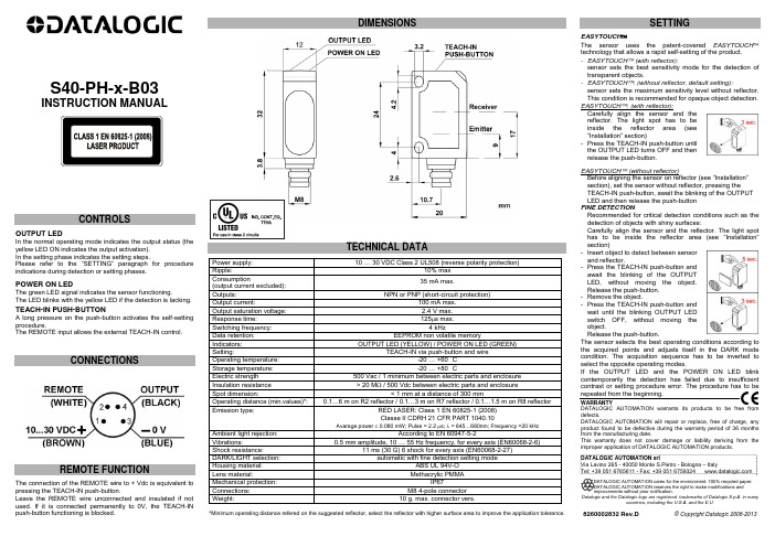
S40-PH-x-B03INSTRUCTION MANUALCONTROLSOUTPUT LEDIn the normal operating mode indicates the output status (the yellow LED ON indicates the output activation). In the setting phase indicates the setting steps.Please refer to the “SETTING” paragraph for procedure indications during detection or setting phases.POWER ON LEDThe green LED signal indicates the sensor functioning.The LED blinks with the yellow LED if the detection is lacking.TEACH-IN PUSH-BUTTONA long pressure on the push-button activates the self-setting procedure.The REMOTE input allows the external TEACH-IN control.CONNECTIONSREMOTE FUNCTIONThe connection of the REMOTE wire to + Vdc is equivalent to pressing the TEACH-IN push-button.Leave the REMOTE wire unconnected and insulated if not used. If it is connected permanently to 0V, the TEACH-IN push-button functioning is blocked.DIMENSIONSTECHNICAL DATA Power supply: 10 … 30 VDC Class 2 UL508 (reverse polarity protection)Ripple: 10% maxConsumption (output current excluded):35 mA max. Outputs: NPN or PNP (short-circuit protection) Output current: 100 mA max. Output saturation voltage: 2.4 V max. Response time: 125μs max. Switching frequency: 4 kHzData retention: EEPROM non volatile memoryIndicators: OUTPUT LED (YELLOW) / POWER ON LED (GREEN)Setting: TEACH-IN via push-button and wireOperating temperature: -20 … +60 °CStorage temperature: -20 … +80 °CElectric strength 500 Vac / 1 minimum between electric parts and enclosure Insulation resistance > 20 M Ω / 500 Vdc between electric parts and enclosure Spot dimension: < 1 mm at a distance of 300 mm Operating distance (min.values)*: 0.1…6 m on R2 reflector / 0.1…3 m on R7 reflector / 0.1…1.5 m on R8 reflector Emission type: RED LASER: Class 1 EN 60825-1 (2008)Classe II CDRH 21 CFR PART 1040.10Avarage power ≤ 0.080 mW; Pulse = 2.2 μs; λ = 645…660nm; Frequency =20 kHzAmbient light rejection: According to EN 60947-5-2Vibrations:0.5 mm amplitude, 10 … 55 Hz frequency, for every axis (EN60068-2-6)Shock resistance:11 ms (30 G) 6 shock for every axis (EN60068-2-27)DARK/LIGHT selection: automatic with fine detection setting modeHousing material: ABS UL 94V-O Lens material:Methacrylic PMMAMechanical protection: IP67Connections: M8 4-pole connector Weight:10 g. max. connector vers.*Minimum operating distance refered on the suggested reflector, select the reflector with higher surface area to improve the application tolerance.SETTINGEASYTOUCH ™The sensor uses the patent-covered EASYTOUCH ™ technology that allows a rapid self-setting of the product. - EASYTOUCH ™ (with reflector):sensor sets the best sensitivity mode for the detection of transparent objects.- EASYTOUCH ™: (without reflector, default setting):sensor sets the maximum sensitivity level without reflector. This condition is recommended for opaque object detection. EASYTOUCH ™: (with reflector):Carefully align the sensor and the reflector. The light spot has to be inside the reflector area (see “Installation” section)- Press the TEACH-IN push-button until the OUTPUT LED turns OFF and then release the push-button.EASYTOUCH ™ (without reflector)Before aligning the sensor on reflector (see “Installation” section), set the sensor without reflector, pressing the TEACH-IN push-button, await the blinking of the OUTPUT LED and then release the push-button FINE DETECTIONRecommended for critical detection conditions such as the detection of objects with shiny surfaces: Carefully align the sensor and the reflector. The light spothas to be inside the reflector area (see “Installation” section)- Insert object to detect between sensorand reflector. - Press the TEACH-IN push-button and await the blinking of the OUTPUTLED, without moving the object. Release the push-button.- Remove the object. - Press the TEACH-IN push-button and wait until the blinking OUTPUT LED switch OFF, without moving theobject. Release the push-button. The sensor selects the best operating conditions according to the acquired points and adjusts itself in the DARK mode condition. The acquisition sequence has to be inverted toselect the opposite operating modes.If the OUTPUT LED and the POWER ON LED blinkcontemporarily the detection has failed due to insufficient contrast or setting procedure error. The procedure has to be repeated from the beginning. WARRANTY DATALOGIC AUTOMATION warrants its products to be free from defects.DATALOGIC AUTOMATION will repair or replace, free of charge, any product found to be defective during the warranty period of 36 months from the manufacturing date.This warranty does not cover damage or liability deriving from the improper application of DATALOGIC AUTOMATION products.DATALOGIC AUTOMATION srlVia Lavino 265 - 40050 Monte S.Pietro - Bologna – ItalyTel: +39 051 6765611 - Fax: +39 051 6759324 Datalogic and the Datalogic logo are registered trademarks of Datalogic S.p.A. in manycountries, including the U.S.A. and the E.U.8260002832 Rev.D © Copyright Datalogic 2008-2013。
pH传感器的校准方法

pH 电极的校准程序:
1.标准溶液的获取:准备两种pH缓冲液,二者间的 pH 值之差一定要大于2pH。
通常最容易获取的pH缓冲液分别是:pH4.00,pH6.86,pH9.18。
一般情况下,每种标准液的体积以100~200ml为宜。
2.清洗,将pH电极从管路上取下,用蒸馏水冲洗
3.长按变送器上Enter键进入CALIBRATE界面(校准菜单),依次按▲▲▲▼按钮进入校准菜单“输入密码输入的密码显示为XXXX”。
4.设定好温度后,按▼键使得变送器界面显示为Standard(标准),按→键进入标准测定。
将探头插入到缓冲溶液中,待读数稳定后,按▲▼键将示数调为缓冲溶液的ph值,按Enter键确定
5.按▼键使得变送器界面显示为Slope(斜率),按→键进入斜率测定。
将探头插入到另一种缓冲溶液中,待读数稳定后,按▲▼键将示数调为缓冲溶液的ph 值,按Enter键确定。
此时,已完成两点校准。
* 为得到最佳校准结果,在稳定期间轻轻搅动缓冲液中的电极5秒钟。
pH传感器问题与解决方法。
简易操作手册_OPTISENS PH_131024
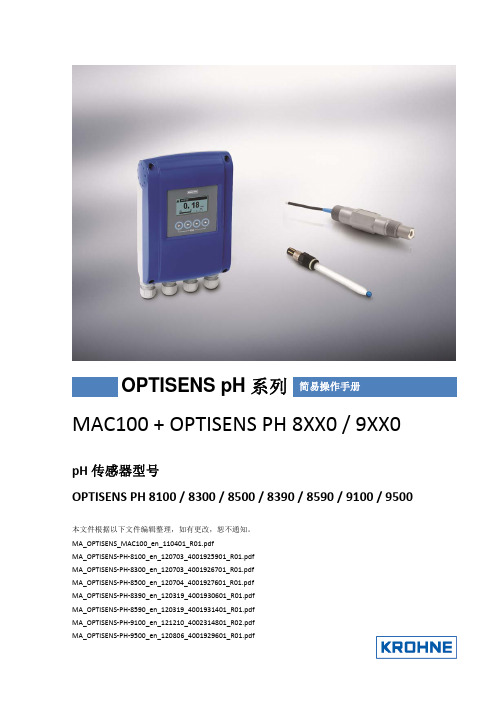
MAC100 + OPTISENS PH 8XX0 / 9XX0pH 传感器型号OPTISENS PH 8100 / 8300 / 8500 / 8390 / 8590 / 9100 / 9500本文件根据以下文件编辑整理,如有更改,恕不通知。
MA_OPTISENS_MAC100_en_110401_R01.pdfMA_OPTISENS ‐PH ‐8100_en_120703_4001925901_R01.pdf MA_OPTISENS ‐PH ‐8300_en_120703_4001926701_R01.pdf MA_OPTISENS ‐PH ‐8500_en_120704_4001927601_R01.pdf MA_OPTISENS ‐PH ‐8390_en_120319_4001930601_R01.pdf MA_OPTISENS ‐PH ‐8590_en_120319_4001931401_R01.pdf MA_OPTISENS ‐PH ‐9100_en_121210_4002314801_R02.pdf MA_OPTISENS ‐PH ‐9500_en_120806_4001929601_R01.pdf简易操作手册OPTISENS pH 系列仪表接线MAC100 接线:继电器接线端,3路开关继电器,最大230V,4A注意事项:1.电源接线用一字螺丝刀顶住塑料扳机后将线插入即可,如用其他工具可能导致塑料扳机损坏。
2.4‐20mA输出最多可用A/A‐ B/B‐ C/C‐ 三组,需在设置菜单内设置对应的输出参数及量程。
3.传感器接线端(输入通道)标配是单通道,即Pos.A,接线参照说明书所示与接线排上的字母对应。
* 请务必确认现场供电电压与订购仪表的电源电压一致后,再给仪表送电!传感器电缆接入线连接方法:一体型电缆 OPTISENS pH 8390 / PH8590线缆 接线端Pos.A/B同轴内屏蔽(黑) N同轴电缆(透明) OPt100(白) PPt100(红) XVP电缆(带温度补偿)OPTISENS PH 8100 / 8300 / 8500线缆 接线端Pos.A/B同轴内屏蔽(黑) N同轴电缆(透明) OPt100(绿) PPt100(白) X地线(黄绿) S其余线缆包好即可Din‐coax同轴电缆(无温度补偿)OPTISENS PH 8300 / 8500 / 9100 / 9500线缆 接线端Pos.A/B同轴内屏蔽(红) N同轴电缆(透明) O部分订单可配有Six‐plug电缆Six‐plug电缆接线方式(带温度补偿)OPTISENS PH 8300 / 8500 (2013年10月前订购) 线缆 接线端Pos.A/B同轴内屏蔽(接线头灰) N同轴电缆(接线头红) OPt100(绿) PPt100(白) X地线(黄绿) S其余线缆包好即可仪器操作首次安装时建议核查并设置如下参数:测量范围,测量单位,温度补偿,输出范围,时钟菜单设置在主界面用↓ 或↑ 翻页可查看测量界面,曲线及状态信息在主界面按住 > 2.5 秒可进入设置菜单在菜单界面用↓ 或↑ 选择菜单,用 > 可进入菜单,用“回车”进行确认并退出在任何菜单中都可同时按住 > 和 ↑ 返回上一级菜单菜单说明A Quick setup 进行快速启动的操作,包括仪器校准,4‐20mA输出设置等常规设置B Test 进行仪表测试,包括查看仪器状态信息,以及模拟输出信号C Setup 最主要的设置菜单,包括了绝大部分仪器的参数设置pH校准将pH电极从介质中取出,清洗在主界面按住 > 2.5秒进入设置菜单,再按 > 进入 Quick setup,选择 pH cal.Temp comp. 温度补偿选择 automatic 自动补偿,如在常温下也可选择off当屏幕显示 calib. buffer 1时,将pH传感器放入中性校准液中(6.86或7.00),稍微搅动后按回车屏幕显示 pH1 set value,输入校准液pH值并回车,界面显示倒计时,倒计时结束后,屏幕显示 calib. buffer 2,将pH传感器放入酸性校准液中(4.00),稍微搅动后按回车,屏幕显示 pH2 set value,输入校准液pH值并回车,界面再次倒计时,倒计时结束后,校准完成。
菲尔斯特 pH 值传感器使用手册说明书
菲尔斯特PH值传感器使用手册1.技术参数参数指标测量范围0-14pH温度测量范围0-80.0℃,0-60℃斜率≥96%零点电位7.00±0.25壳体材质PC,PBT防腐液接界聚四氟乙烯连接螺纹NPT3/4,M39*1.5信号线长度5M(可定制)耐压范围0-4bar膜电阻<500MΩ防护等级IP68输出4-2mA和RS485信号线信号线防护套防护套2.使用前说明2.1使用之前请仔细研读本说明2.2本说明适用于菲尔斯特品牌的智慧型pH系列电极2.3传感器敏感膜球泡属于易损品,一旦损坏将无法修复2.4打开包装之前请检查包装是否有损坏,如果外包装已破损,请不要继续打开包装,请立即与菲尔斯特传感器品牌最近的授权代理商或直接与我们取系,运输方代表到场后共同打开包装检验电极是否损坏,建议拍照取证。
2.5如外包装完好但电极损坏请立即与菲尔斯特传感器品牌最近的授权代理商或直接与我们联系,并将电极原包装寄回。
2.6不要将电极放在蒸馏水或去离子内存储。
2.7测量过程中,电极敏感膜球泡处若有污垢、黏着物或结垢,将会导致测量值不准确或波动,应及清洗和校准。
2.8传感器球泡内若有空气,将会导致测量值不准或波动,可以轻轻甩动电极将气泡甩去。
2.9该说明书所阐述的内容将随产品不断改进而改变,本公司在说明书中将不另行通知,并且不承担由此带来的后果。
3.电极的接线3.1请仔细按照说明书接线,错误的接线将导致产品完全损坏。
3.2严禁在所有线缆连接完成之前送电,发免发生危险,在送电之前请务必仔细检查系统所有接线,确认完成正确后方可送电。
电极出线M12接口注:具体接线方式以产品标识为准4.电极的活化4.1电极需在3MKCL溶液中活化4.2干放的电极需活化后才能使用。
5电极的标定5.1仪表出厂前一般已做标定,用户可直接投入使用。
5.2标定时建议使用两点法标定,通常先用pH6.86或7.00缓冲液标定位,然后用pH4.01或9.18缓冲液确定斜率。
PHE-45P pH 传感器说明书
Figure 1-1 PHE-45P Sensor Dimensions (standard, convertible-style)1.4 Important Notes 1. The PHE-45P process electrode is made of glass andcan break if not handled properly. Should the electrodeever break, USE CAUTION when handling the sensorto avoid serious cuts.2. The glass electrode must be wetted at all times toensure proper functionality. PHE-45P sensors areshipped with a fluid-filled cap over the electrode toenable immediate use (remove cap before installing,save for storage and shipping purposes). ElectrodesNote: Integral Mount suitablefor loop-powered versionONLYFigure 2-1 Integral Mount to PHTX-45 Monitor/AnalyzerFigure 2-2 PHE-45P Sensor TypesFigure 2-3 Cable Description, Model PHE-45PNote:Only the custom 6-wire shielded interconnect cable attached to the sensor must be used when connectingthe Model PHE-45P sensor to the analyzer. Thishigh-performance, double shielded, polyethylenejacketed cable is specially designed to provide theproper signal shielding for the sensor used in thissystem. No substitutions can be made. Substitutedcables may cause problems with system perform-ance.Voltage between Terminals 9 and 10 MUST be between 16 and 35 VDC.Earth ground into Terminal 12 is STRONGLY recommended. This connection can greatly improve stability in electrically noisy environments.Figure 2-4 Wiring Diagram, PHE-45P Sensor and PHTX-45 TransmitterFigure 3-1 Replacing the Saltbridge and Reference Buffer。
在线PH数字式传感器使用方法
在线PH传感器使用手册目录一、设备应用环境说明 (3)二、技术参数、功能和规格要求 (3)1. 技术参数 (3)2. 尺寸图 (4)3. 通讯协议 (4)4. 安装方式 ....................... .. (6)5. 接线 .................... .. (7)6. 质量保证 ............... . (7)7. 配件和备件 ................... . (7)8. PH 电极使用保养 (7)9. 售后服务承诺 (8)用于酸/碱/盐溶液、化学反应过程中、工业生产过程中,能够满足大多数工业应用对在线PH测量的苛刻要求。
★信号输出: RS485( Modbus/RTU 协议)。
★方便连接到 PLC、DCS、工业控制计算机、通用控制器、无纸记录仪器或触摸屏等第三方设备。
双高阻抗差动放大器,抗干扰强,响应速度快。
★专利的 pH 探头,内部参比液在至少 100KPa(1Bar)的压力下,极其缓慢的从微孔盐桥中渗出,其正向渗出持续20 个月以上。
这样的参比系统非常稳定,电极寿命比普通工业电极成倍延长。
★易于安装:3/4 英寸 NPT 螺纹(管螺纹),便于安装在管道和罐体。
探头和显示部分可分开,通过电缆连接。
★ IP68 防护等级。
1. 技术参数2.3. 数据通讯3.1 数据格式Modbus 通信默认的数据格式为: 9600、n、8、1(波特率 9600bps、1 个起始位、8 个数据位、无校验、1 个停止位)。
波特率等参数可以定制。
3.2 信息帧格式a) 读数据指令帧:b) 读数据应答帧:c) 写数据指令帧:d) 写数据应答帧(同写数据指令帧):3.3 寄存器地址注意:a) 寄存器地址为根据 Modbus 协议定义的带寄存器类型的寄存器起始地址(括号中的 16进制表示的实际的寄存器起始地址)。
b) 更改传感器地址时,返回指令中的传感器地址为更改后的新地址。
ph传感器操作手册
pH传感器操作说明书中国区代理商:上海卯林机电设备有限公司地址:上海市闵行区外环路352号D205室电话:传真:email:网址:目录1. 安全预防措施 (3)1.1 健康与安全 (3)1.2 环境保护 (3)1.3 化学品 (3)2 pH传感器 (4)2.1 测量原理 (4)2.2 技术规格 (4)2.3 耐压型pH流通池 (4)3 设置 (5)3.1 安装 (5)3.1.1 传感器安装 (5)3.1.2 耐压型密闭式流通池 (5)3.1.3 敞开式流通池 (6)4. 传感器接线 (7)4.1 ph传感器输入接线.........。
. (7)5. 传感器调试 (8)5.1 开始使用前的准备 (8)5.2 安装 (8)5.3 校准与标准化 (8)5.3.1 校准 (9)5.3.2 标准化 (10)5.3.3 高级维护选项 (10)6. 传感器维修 (11)6 .1 传感器清洗 (11)6.2 传感器保存 (11)7. 维修 (12)1. 安全预防措施●在打开、设置或操作这台仪器之前,请阅读整个手册。
●在维护或更换零件之前确保电源断开。
●在维护或更换零件之前确保仪表没有外部的压力(比如气压或液压)。
●不遵守这些预防措施可能导致人体受伤或损坏设备。
●1.1 健康与安全在接/拆电源线和传感器信号线的时候,确保仪器已经断电。
pH传感器是用来测量水中pH浓度的,所以取放传感器的时候,请带好合适的PPE。
1.2 环境保护此传感器是玻璃结构,它封装有塑料壳体和银/卤化银配件。
使用它的请考虑环境的影响,当到了使用寿命的时候,请根据当地的法律法规进行回收,请勿随意抛弃。
1.3 化学品连接到Crius@控制器的传感器会接触到一些危险的化学品,拿放传感器的时候请要万分小心。
注意(CAUTION)当使用此设备时,必须遵守现场的突发情况和个人安全防护准则PPE: 防护服,防护手套,护目镜示例2. pH传感器2.1 测量原理当使用电极时,pH被以电位的方式进行测量。
- 1、下载文档前请自行甄别文档内容的完整性,平台不提供额外的编辑、内容补充、找答案等附加服务。
- 2、"仅部分预览"的文档,不可在线预览部分如存在完整性等问题,可反馈申请退款(可完整预览的文档不适用该条件!)。
- 3、如文档侵犯您的权益,请联系客服反馈,我们会尽快为您处理(人工客服工作时间:9:00-18:30)。
pH传感器操作说明书中国区代理商:上海卯林机电设备有限公司地址:上海市闵行区外环路352号D205室电话:传真:email:网址:目录1. 安全预防措施 (3)健康与安全 (3)环境保护 (3)化学品 (3)2 pH传感器 (4)测量原理 (4)技术规格 (4)耐压型pH流通池 (4)3 设置................................................................................................ (5)安装 (5)传感器安装.................................................................................................................................................... .. (5)耐压型密闭式流通池....................................................................................................................................... (5)敞开式流通池 (6)4. 传感器接线 (7)ph传感器输入接线.........。
. (7)5. 传感器调试 (8)开始使用前的准备 (8)安装 (8)校准与标准化 (8)校准.................................................................................................................................... . (9)标准化 (10)高级维护选项 (10)6. 传感器维修 (11)6 .1 传感器清洗.......................................................................................................................................... .. (11)传感器保存.......................................................................................................................................... (11)7. 维修 (12)1. 安全预防措施在打开、设置或操作这台仪器之前,请阅读整个手册。
在维护或更换零件之前确保电源断开。
在维护或更换零件之前确保仪表没有外部的压力(比如气压或液压)。
不遵守这些预防措施可能导致人体受伤或损坏设备。
健康与安全在接/拆电源线和传感器信号线的时候,确保仪器已经断电。
pH传感器是用来测量水中pH浓度的,所以取放传感器的时候,请带好合适的PPE。
环境保护此传感器是玻璃结构,它封装有塑料壳体和银/卤化银配件。
使用它的请考虑环境的影响,当到了使用寿命的时候,请根据当地的法律法规进行回收,请勿随意抛弃。
化学品连接到Crius@控制器的传感器会接触到一些危险的化学品,拿放传感器的时候请要万分小心。
注意(CAUTION)当使用此设备时,必须遵守现场的突发情况和个人安全防护准则PPE: 防护服,防护手套,护目镜示例2. pH传感器测量原理当使用电极时,pH被以电位的方式进行测量。
当它与溶液接触的时候会通过pH电极玻璃膜产生一个电势,这个电势变化同pH变化成正比,但是需要一个常数电势来对比这个变化,这个常数电势由内置的参比电极提供。
在酸性或者碱性溶液中,膜片外表面上的电压变化同氢离子变化成等比例关系,如下公式所示:E=总电势差(mv)E0=标准溶液R=气体常数T=绝对温度N=电子数量F=法拉第常数【H+】=氢离子活性技术规格传感器类型: pH2长度: 170mm壳体材料: ,Kynar,316SS接头尺寸:外径最大压力: 100Psi测量范围: 0-14耐压型pH流通池耐压型pH/Orp流通池设计用来允许电极可以在水中被看见,而且不需要减压到大气压。
它可以在线安装,如果压力允许,也能旁通安装。
如果是旁通式安装,那么要确保取样点压力高于插入点的压力以保证有水流流过传感器。
最大的允许压力要低于传感器的额定压力。
3. 设置安装传感器安装pH传感器可以被安装在敞开式单传感器流通池,敞开式双传感器流通池,单传感器密闭式耐压型流通池,单传感器自动清洗装置,双传感器自动清洗装置或者T型接头里,也可以进行浸没式安装(仅限pH3,phH传感器)。
所有情况下,传感器安装都要注意以下几个方面:传感器不能暴露在压力波动超过3Bar(43Psi)环境下。
推荐流量为min,敞开式流通池最小流量要求为mini,自清洗安装推荐流量为8-14l/min推荐温度为0-80℃(pH1,pH2,pH3),0-95℃(pH4),一些传感器带有温度补偿功能。
不允许传感器处于干燥状态。
耐压型密闭式流通池竖直安装取样进口压力高于回水压力确保水流通过传感器。
安装稳定,远离震动源。
压力不要超过传感器的最大允许压力。
请确保有足够的空间来安装、移除电极。
A=138mmB=79mmC=D=75mmE=100mm耐压型密闭式流通池规格进口流量:最小流量:min典型流量:min最大压力:1Bar敞开式流通池入口: 1/4”或6mm宝塔形,或8mm快插出口: 1/2”或12mm宝塔形探头编号:可用单孔或双孔流通池维护隔离:球阀流量:min(首选流量min)入口压力:流通池压力:相当于零,开放式流通池重量:1kg(单孔)(双孔)过滤器(如果需要):100um流量开关:如果样品没有流量将作为一个选项提供低流报警4 接线pH传感器输入接线大多数传感器都是通过线路板上的模拟输入接口进行传感器接线。
线缆类型和等级-高阻抗电极采用多芯同轴电缆(例如:pH电极)65 传感器调试开始使用前的准备取下电极上的瓶子或者保护帽并用蒸馏水充分清洗。
在运输过程中,气泡可能会跑到电极感应泡里,抓住电极对着光,检查下电极感应泡里是否有气泡,如果里面有气泡,抓住电极向下甩(就像甩体温计一样)来消除气泡。
安装pH传感器可以有几种安装方式可供选择,流通池安装,T型头安装,螺纹头安装等,安装方式在采购的时候就已经确认。
pH3和ph4传感器还能进行浸没式安装。
如果你把不允许浸没式安装的电极(pH1,pH2)进行浸没式安装,可能会导致严重的损坏。
这些传感器配有3/4” NPT公接头或者3/4”BSP公接头来连接支杆,不要使用有弹性的电缆使得电极悬挂着摇晃,不然可能会损坏电极。
校准/标准化(Calibration/Standardising)有两种方法来校准/标准化 pHsense传感器。
第一个是需要最少2到5个pH标准液来”校准(C alibrating)”传感器,第二种只需要一个pH标准液,一个pH试剂或者一个已经校准过的pH传感器。
第二种方法被成为“标准化(S tandardizing)”,因为它并不是一种真正的传感器校准。
pH校准需要设置零点和高点两个参数(offset and slope)。
当pH变化的时候,测量得到的电压也会变化,两者变化关系如下:pH值是7的时候电压为0mV,根据设备的不同,也许在pH为7的时候,测量的电压会稍微有点偏移0mV。
因此,使用pH值6-8的校准缓冲液就非常重要,它可以帮助确保pH为7的时候,电压为0mV。
这就是所谓的”零点(offset”)”.校准(Calibration)使用2到5个标准液可进行pH校准,校准液越多,校准就会越理想。
校准的时候,零点和高点都会被校准。
通常使用3个标准液进行校准就可以,但是在一些pH监测非常严格的应用中,建议进行5点校准。
你可以通过pH传感器预览或者以下方式进入校准功能:从菜单上选择传感器<Sensor>Options Maitenance Calibration根据你选择的传感器类型,你也许需要在选项里先进行温度校准,因为pH值同温度有关。
根据屏幕上的架构和提示,选择”Y e s”来校准温度,温度校准开始后,会进行30秒倒计时。
在倒计时时,控制器会计算传感器信号的稳定性,如果这个过程中,传感器被认为是稳定的,那么会有一个输入真实温度的选项,这个真实温度可用温度计测量样品水温度来获得。
只有在传感器信号是稳定的情况,控制器才允许温度读值被修改。
推荐使用3个或者更多个pH标准液(通常为pH 4,7,10)来校准,然后,也许只需要两个标准液来校准有Crius 控制的pH传感器。
校准温度后,或者在提示你是否校准温度的时候,你选择了“No”,那么你会自动进入校准导引,它会通过以下步骤导引你完成校准:1. 从流通池里取出pH电极2. 把电极放入一个pH标准校准液中,先用那个标准液进行校准并不重要。
3. 按(Next)并确等待知道读数变得稳定,读数稳定后,再按”Next”,30秒倒计时开始,倒计时过程中,控制器从校准中获取数据。
倒计时过程中,如果读数不稳定,那么校准会失败。
4. 系统会自动识别常规标准液(例如:pH=,如果系统识别到标准液,它会要你确认这个是否是标准液,选择”Yes”后,它会自动会有标准液的pH值。
如果不是这个标准液值,那么建议选择”No”然后手动输入使用的标注液值。
如果控制器没有识别到标准液,你会被要求手动输入pH值,pH值输入后,请按”Next”。
见控制器操作手册。
5. 完成后,控制器会要求你重复上面过程进行第二点校准。
6. 输入第二点pH校准值后,控制器会温你是否需要校准另外一点,选择”Yes”会带你再一次进入上面步骤,选择”No”会显示校准结果。
请记住,我们建议至少进行3点校准,如果可能,最好进行5点校准。
只有在“校准结果(Calibration Results)”页面选择“应用(A pply)”后,校准才会被保存。
校准结果页面显示的结果来源于校准标准液,从这些结果获得的计算过的高点和零点,也会显示校准和计算得到传感器健康状况的可信度。
典型零点在-30到+30mv之间,典型的高点在-50和-60之间,如果你的数值偏离了这些范围,请查看”维修导引(Troubleshooting Guide)。
传感器的”健康(H eath)’是通过对比现有高点和期望高点并计算得到的。
正常数值可能是100%,但是如果大于120%,那么可能是使用了不正确的校准标准液,如果小于80%,那么意味着需要清洗电极,如果清洗后,数值还是小于80%,那么就要考虑更换pH传感器了。