螺栓预紧结构用Hypermesh做接触实例
如何在hypermesh中连接柔性单元(二保焊螺栓)如何在hypermesh中实现柔性体-柔性体的连接(二保焊、螺栓)
【包子原创教程】如何在hypermesh中连接柔性单元(二保焊螺栓)如何在hypermesh中实现柔性体-柔性体的连接(二保焊/焊缝、螺栓)教程简介:hypermesh(dyna模块)的柔性单元之间的连接一般用来模拟二保焊/焊缝和螺栓连接,本教程将详细向你介绍如何如何实现这种连接。
二保焊(焊缝)、螺栓连接,一般通过刚性单元rigid模拟,和柔性单元连接。
注意:rigid 单元card image=none,没有材料和属性。
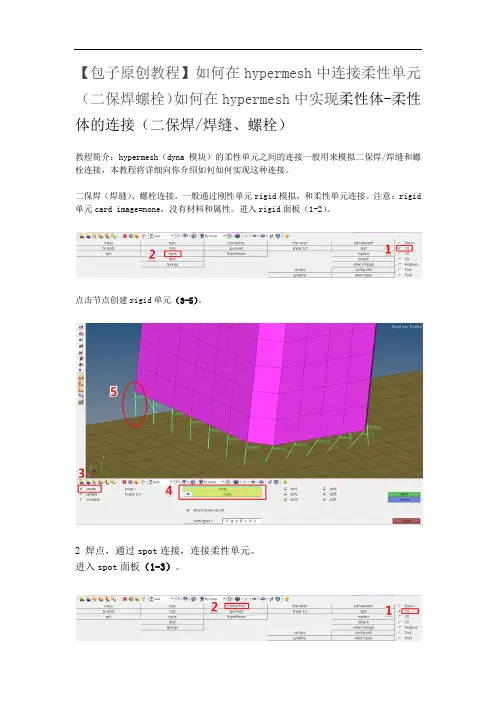
进入rigid面板(1-2)。
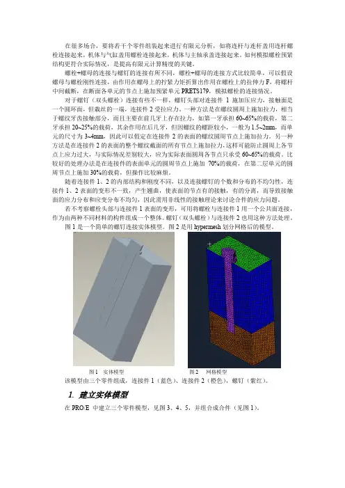
点击节点创建rigid单元(3-5)。
2 焊点,通过spot连接,连接柔性单元。
进入spot面板(1-3)。
单击nodes(5),选择焊点所在节点(6-7),一般模型中会给出焊点的位置数据,比如用小球表示。
选择焊点连接的部件(8-9),连接部件的类型(10)选择elems,根据实际情况选择层数,图中total 2表示二层焊(11)。
容差要大于部件之间的距离(12)。
材料类型选择mat100(hexa)(13),输入焊点直径(14)。
焊点单元绿色表示成功,黄色表示失效,红色表示创建失败。
创建焊点材料。
注意,一般不使用自动生成的材料、属性和接触,删除之后重新创建。
创建材料,选择100号材料(15-16),编辑材料参数(17)。
输入材料参数(18-19)。
创建材料属性,选择实体单元(因为焊点是实体)(20-23)。
给焊点单元赋予材料和属性。
创建焊点和部件之间的接触。
进入接触面板(24-25)。
创建接触(26-27),type选择ContactSportweld(28),进入编辑面板(29)。
输入参数,静摩擦因数(FS)和动摩擦因数(FD)(30-31)。
添加主部件,选择被焊点连接的部件(33-34)。
添加从部件,选择焊点单元(35-36)。
单击review检查接触是否正确(38),蓝色显示的是主部件,红色显示的是从部件(38)。
螺栓预紧结构用Hypermesh做接触实例
在很多场合,要将若干个零件组装起来进行有限元分析,如将连杆与连杆盖用连杆螺栓连接起来,机体与气缸盖用螺栓连接起来,机体与主轴承盖连接起来。
如何模拟螺栓预紧结构更符合实际情况,是提高有限元计算精度的关键。
螺栓+螺母的连接与螺钉的连接有所不同,螺栓+螺母的连接方式比较简单,可以假设螺母与螺栓刚性连接,由作用在螺母上的拧紧力矩折算出作用在螺栓上的拉伸力F ,将螺杆中间截断,在断面各单元的节点上施加预紧单元PRETS179,模拟螺栓的连接情况。
对于螺钉(双头螺栓)连接有些不一样,螺钉头部对连接件1施加压应力,接触面是一个圆环面,但栽丝的一端,连接件2受拉应力。
一种方法是在螺纹圆周上施加拉力,相当于螺纹牙齿接触部分,而且主要在前几牙上存在拉力,如第一牙承担60~65%的载荷,第二牙承担20~25%的载荷,其余作用在后几牙,但因螺纹的螺距较小,一般为1.5~2mm ,而单元的尺寸为3~4mm ,因此可以假定在连接件2的表面的螺纹圆周节点上施加拉力。
另一种方法是在连接件2的表面的整个螺纹截面的所有节点上施加拉力,这样可能防止圆周上各节点上应力过大,与实际情况差别较大,应为实际表面圆周各节点只承受60~65%的载荷。
比较好的处理办法是在连接件的表面单元的圆周节点上施加70%的载荷,在第二层单元的圆周节点上施加30%的载荷,但操作比较麻烦。
随着连接件1、2的内部结构和刚度不同,以及连接螺钉的个数和分布的不均匀性,连接件1、2表面的变形不一致,产生翘曲,使表面的节点有的接触,有的分离,而导致接触面的应力分布和应变分布不均匀,因此需用非线性的接触理论来讨论合件的应力问题。
若不考察螺栓头部与连接件1表面的变形,可用将螺栓与连接件1用一个公共面连接,作为由两种不同材料的构件组成一个整体。
螺钉(双头螺栓)与连接件2也用这种方法处理。
图1是一个简单的螺钉连接实体模型。
图2是用hypermesh 划分网格后的模型。
图1 实体模型 图2 网格模型该模型由三个零件组成,连接件1(蓝色)、连接件2(橙色),螺钉(紫红)。
螺栓螺纹三维接触有限元分析
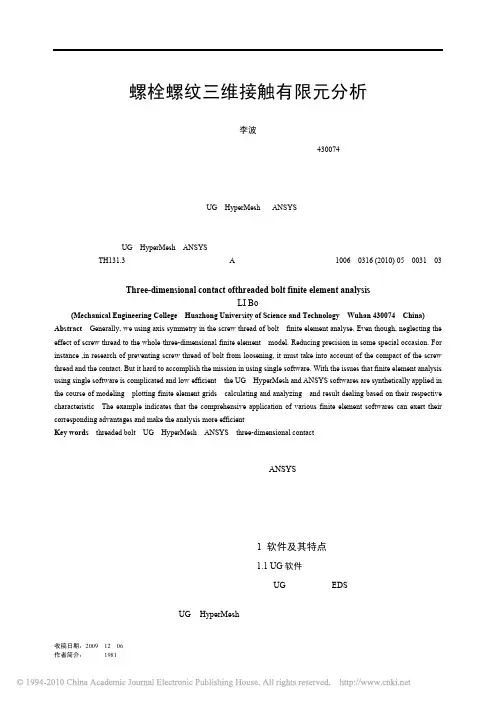
机械 2010年第5期 总第37卷 计算机应用技术 ・31・———————————————收稿日期:2009-12-06作者简介:李波(1981-),湖北武汉人,硕士研究生,主要研究方向为机械结构分析。
螺栓螺纹三维接触有限元分析李波(华中科技大学 机械科学与工程学院,湖北 武汉 430074)摘要:在对螺栓螺纹的分析中,一般采用的方法是将螺栓简化为轴对称,建立轴对称有限元模型进行分析,即使是建立三维模型也是忽略了螺纹部分对整个有限元模型分析的影响。
在一些特殊的分析情况下,这样会大大降低分析的精度。
比如,在对螺栓螺纹防松机理方面的研究中,就必须考虑螺纹部分及其接触对整个分析过程的影响,而采用单一的有限元软件又很难完成。
正是基于这一原因,根据UG 、HyperMesh 和ANSYS 软件的特点,综合运用其长处可以完成螺栓螺纹从几何建模、网格划分、分析计算到结果处理的整个过程.实例表明,综合运用各种软件,有利于发挥每种软件的优点,大大提高有限元分析的效率。
关键词:螺栓螺纹;UG ;HyperMesh ;ANSYS ;三维接触中图分类号:TH131.3 文献标识码:A 文章编号:1006-0316 (2010) 05-0031-03Three-dimensional contact ofthreaded bolt finite element analysisLI Bo(Mechanical Engineering College ,Huazhong University of Science and Technology ,Wuhan 430074,China) Abstract :Generally, we using axis symmetry in the screw thread of bolt finite element analyse. Even though, neglecting the effect of screw thread to the whole three-dimensional finite element model. Reducing precision in some special occasion. For instance ,in research of preventing screw thread of bolt from loosening, it must take into account of the compact of the screw thread and the contact. But it hard to accomplish the mission in using single software. With the issues that finite element analysis using single software is complicated and low efficient ,the UG ,HyperMesh and ANSYS softwares are synthetically applied in the course of modeling ,plotting finite element grids ,calculating and analyzing ,and result dealing based on their respective characteristic .The example indicates that the comprehensive application of various finite element softwares can exert their corresponding advantages and make the analysis more efficient .Key words :threaded bolt ;UG ;HyperMesh ;ANSYS ;three-dimensional contact有限元法是随着计算机的发展而迅速发展起来的一种现代计算方法。
Hypermesh 2017or2019_新建接触步骤
新建目标面单元类型,设置如图 6 所示。(根据实际实际情况设置关键字,图 中仅为示例)
图 7 新建接触面单元类型 新建接触面单元类型,设置如图 7 所示。(根据实际实际情况设置关键字,图 中仅为示例)
4. 新建接触面(Contact Surface)
新建并选中接触面,点击“Elements”,如图 8,按照图 9 第三步选择吊带(红 色组件)的单元,第四步选择法向面节点(选择的节点尽量多一点),如图 10。 新建的接触面即图 11 中的青色部分。
图 13
图 14
图 15
图 16
图 17 在标签区选中新建的接触组,进行如图 18、图 19、图 20、图 21 和图 22 的设 置,到这就完成了在 Hypermesh 2017/2019 中新建接触的所有步骤。
图 18 图 19
图 20 图 21
图 22
Hypermesh 2017/2019 新建接触步骤
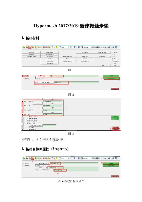
1. 新建材料
图1 图2
图3 根据图 1、图 2 和图 3 新建材料。
2. 新建目标面属性(Propertity)
图 4 新建目标面属性
图 5 设置实常数 按图 4 所示新建目标面属性,实常数保持)
图8 图8
图 9 选择接触面单元 图 10 选择法向面的节点
图 11 吊带的接触面 按照上述步骤新建安全座的接触面,如图 12 所示。
图 12 安全座的接触面
5. 新建接触组(Group)
按图 13 方式从主菜单中进入 interfaces 界面,并按照图 14 创建接触组,并根据 图 15、图 16 和图 17 进行操作,主面(master)对应的是接触面,从面(slave) 对应目标面。
hyperworks接触分析
好问题,学习了
报告 道具 TOP 8#
/viewthread.php?tid=932569&highlight=contactsurf 2011-5-7
hypermesh中定义接触contact的问题 - CA01:HyperMesh&HyperView--前后... 页码,6/8
Powered by Discuz! 7.0.0 Licensed
© 2001-2009 Comsenz Inc.
中国仿真互动 ( 沪ICP备07510919号) | 联系我们 | Archiver | WAP
GMT+8, 2011-5-7 18:36, Processed in 0.112385 second(s), 9 queries, Gzip enabled.
误
CONTACT interface
1 has Slave
node 900 that lies exactly on the
Master surface with OPENGAP option. Impossible to define pushout
direction.
请教下我少做了哪个步骤..谢
谢.
/viewthread.php?tid=932569&highlight=contactsurf 2011-5-7
hypermesh中定义接触contact的问题 - CA01:HyperMesh&HyperView--前后... 页码,2/8
hypermesh中定义接触contact的问题 - CA01:HyperMesh&HyperView--前后... 页码,4/8
hyperworks接触分析实例教程1
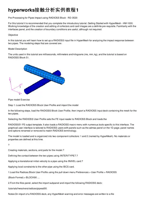
hyperworks接触分析实例教程1Pre-Processing for Pipes Impact using RADIOSS Block - RD-3520For this tutorial it is recommended that you complete the introductory tutorial, Getting Started with HyperMesh - HM-1000. Working knowledge of the creation and editing of collectors and card images are a definite pre-requisite. Familiarity with the interfaces panel, and the creation of boundary conditions are useful, although not required.ObjectiveIn this tutorial you will learn how to set up a RADIOSS input file in HyperMesh for analyzing the impact response between two pipes. The modeling steps that are covered are:Model DescriptionThe units used in this tutorial are milliseconds, millimeters and kilograms (ms, mm, kg), and the tutorial is based on RADIOSS Block 51.Pipe model ExerciseStep 1: Load the RADIOSS Block User Profile and import the modelIn the following steps, load the RADIOSS Block User Profile, then import a RADIOSS input deck containing the mesh for the two pipes.Selecting the RADIOSS User Profile sets the FE input reader to RADIOSS Block and loads theRADIOSS51 FE output template. It also loads a RADIOSS macro menu with numerous tools specific to this interface. The graphical user interface is tailored to RADIOSS users with panels such as the admas panel on the 1D page, panel names and options renamed or removed to match RADIOSS terminology.The model is loaded and is organized into two component collectors: 1 and 2 (named by HyperMesh). No materials or properties are defined at this time.Creating materials, sections, and parts for the model.?Defining the contact between the two pipes using /INTER/TYPE7.?Applying a translational initial velocity to a pipe using the /INIVEL card.?Applying local constraints to the other pipe using the /BCS card.1.Load the Radioss Block User Profile using the pull down menu Preferences > User Profile > RADIOSS(Block Format) > BLOCK90 ....2.From the files panel, select the import subpanel and import the following RADIOSS deck:/tutorials/hwsolvers/radioss/pipesd00.Notes:On import of a RADIOSS deck, any HyperMesh warning and error messages are written to a fileOn import, any RADIOSS cards not supported by HyperMesh are written to the control cardunsupp_cards . This card is accessed from the control cards panel on the BCs page and is apop-up text editor. The unsupported cards are exported with the rest of the model.Care should be taken if an unsupported card points to an entity in HyperMesh. An example of this is an unsupported material referenced by a /PART card. HyperMesh stores unsupported cards as text and does not consider pointers.On import, HyperMesh renumbers entities having the same ID as other entities. In HyperMesh, for example, all elements must have a unique ID. The message file radiossblk.msg provides a list of renumbered elements and their original and new IDs.Step 2: Understand the relationships between the /PART, /SHELL, /MAT and /PROP cards in HyperMeshA /PART shares attributes such as section properties (/PROP) and a material model (/MAT). A group of shells (/SHELL) sharing common attributes generally share a common part ID (PID).The figure below shows how these keywords are mapped to HyperMesh entities:Map to HyperMesh entities Component, property and material collectors are created and edited from the collectors panel.For the RADIOSS keyword interface, there is only one component card image and it is named Part . There are several property card images, such as P1_shell P2_truss , P14_solid . There are many material card images, such as M1_ELAST , M48_HONEYCOMB .The complete list of card images is available from the collectors panel, as you assign card images to the various types of collectors.A HyperMesh card image allows you to view the image of keywords and data lines for defined RADIOSS entities as interpreted by the loaded template. The keywords and data lines appear in the exported RADIOSS input file as you see them in the card images. Additionally, for some card images, you can define and edit various parameters and data items for the corresponding RADIOSS Block.Use the card (card editor) panel from the permanent menu to review and edit card images. Also, for many entities, their card image can be viewed and edited from the panels in which they are created.Step 3: Create a /MAT card In HyperMesh, a /MAT card is associated to a material collector. To relate it to a /PART card, the material collector needs to be assigned to a component collector.You can assign the material to the component collector as you create the component using the createsubpanel of the collectors panel. In situations where the material was not assigned to the component at the time of creation (and in this case, a dummy material is created with the same name as the componentnamed radiossblk.msg . This file is created in the folder from which HyperMesh is started. The content of the file is also displayed in a pop-up window./SHELL elem_ID part_ID> Organized into component collectors/PART part_ID prop_ID mat_ID > Component collector with a componentcard image/PROP prop_ID > Property collector with a property cardimage/MAT mat_ID>Material collector with a material cardimagecollector), update the component collector's definition by assigning the material in the update subpanel of the collectors panel.In this step, create a material collector with the M1_ELAST card image using the collectors panel. This material will be assigned to both pipes.1.Create/edit a material collector with the name elast1, and a M1_ELAST card image using the createsubpanel of the collectors panel.2.In the card previewer, click [Rho_I] to activate its field.For density, specify 7.8 E-6For Young's modulus [E], specify 208For Poisson's ratio [nu], specify 0.30Note:If you have difficulties completing any task with the creation, update or editing of collectors in this tutorial, refer to the on-line help for the collectors panel by clicking help from the permanent menu. Hint:Any collector that you mistakenly create instead of create/edit can be edited using the card image subpanel of the collectors panel.In this step, we created the material we will use for the analysis. We can now define the /PROP card that will be used to define the properties of the elements in the model.Step 4: Create a /PROP cardIn HyperMesh, the /PROP card is assigned to a property collector. To generate this card, create a property collector using either Property collector icon in the toolbar or from the pull down menu Properties > Create. The model consists of two pipes modeled with shell elements. Create a property collector witha /PROP/SHELL card that will be used for all the elements.1.Create a property collector with the name prop shell, set Type = to surface, set card image= toP1_SHELL, and Thickness = 2.5 card.2.In the card previewer for the /PROP/SHELL card, check 2.5for the shell thickness [Thick].Step 5: Assign the /PART, /MAT and /PROP cards to the elementsAssign the /PART card to the component for the coarse pipe and specify the /PROP/SHELL card ID in it.1.Load the Component Collector Update panel from either the toolbar Component collector or from thepull down menu, select Component > Create.2.Click update subpanel.3.Select the pipe 1 component.4.For card image, select PART.5.Assign the material elast1 and property prop shell.6.Click update.Repeat this procedure for pipe 2.Step 6: Create contact cardsRADIOSS contacts are created in the interfaces panel from the Analysis page or from the pull down menu, selectBCs>Create>Interfaces.A RADIOSS contact is a HyperMesh group. When you want to manipulate an /INTER card, such as delete it, renumber it, or turn it off, you need to work with HyperMesh group entities.In this step, create a contact between the two pipes using /INTER/TYPE7. The pipe with the coarser mesh (2) will be the master surface while the one with finer mesh (1) will be the slave surface. RADIOSS has multiple ways to define master andslave entity types from which to choose; in this example define the master and slave entities as components, doing this the master will be exported as /SURF/PART and the slave asa /GRNOD/PART.First create a group interface with the TYPE7card image using the create subpanel of the interfaces panel.Next, add the master and slave to the group using the add subpanel. Lastly, edit the group’s card image using the card image subpanel, and specify a friction coefficient.Automatically TYPE7 is selected for card image.In this step, we defined the contact between the two pipes as /INTER/TYPE7.Creating boundary conditions for a deck in RADIOSS Block can be efficiently carried out with the BC’s Manager available on the Utility Browser , which can be switched on the screen from the View pull down menu.Every load needs to be stored in a load collector with the corresponding card image. For example, store the velocity loads ina velocity load collector and boundary conditions in the respective collector.1.Create a group with the name contact and the TYPE7 card image using the create subpanel of the interfaces panel.2.From the BCs page, select the interfaces panel or from the pull down menu, select BCs > Create > Interfaces .3.Select the create subpanel.4.In the name= field, enter contact .5.For type=, select TYPE7.6.Optionally select a color.7.Click create .8.From the interfaces panel, select the add subpanel.9.Under master , set the entity type to comps :10.Click the yellow comps selector and select the coarser pipe component 2.11.Click update in the master: field, to the right of the yellow comps selector.12.For slave:, select comps .13.Click the yellow comps selector in the slave:line and select the finer mesh pipe component 1.14.In the slave: field, click update .15.Click review to graphically view the entities in the interface, the master entities of the interface are drawn in blue and the slave entities in red.16.Edit the definition of the group, using the card image subpanel to set the static coefficient to 0.10.17.From the interfaces panel, select the card image subpanel.18.Click edit to review the card image.19.Specify 0.10 for the static coefficient [FRIC].Step 7: Create an initial velocity (/INIVEL/TRA)In this step, we will apply a translational initial velocity to the coarse pipe using /INIVEL/TRA applied to a predefined set of nodes /GRNOD/PART.1.Click on BC’s Manager on the Utility browser.2.From the Boundary Conditions Manager, enter the name tran_vel and select the type as initialvelocity under the Create header.3.For creating a entity set of type GRNOD which is referred to in the INIVEL card, click on Parts button andselect the coarser pipe from the GUI (component ID 2). Click proceed.4.In the BC’s Manager, enter the initial velocity components as 0,0 and -30 for Vx, Vy and Vz fields.5.There is an option for creating/referring the initial velocity card to a local coordinate system. However ifnothing is specified, the global coordinate system is selected by default.6.There is an option to specify the size of the load display on the screen under Label Scale.7.Click the create button. Double check in the model browser for your reference that a load collector andan entity set is created.This completes the creation of an initial velocity for the pipe in the negative global Z direction.Step 8: Create a /BCS and constrain the finer mesh pipeIn this step, we will fully constrain the end nodes of the bottom pipe by using the Boundary Conditions Manager.1.In the BCs Manager under the Create subheading, enter the Name SPC and set Select type asBoundary Condition.2.Now specify the node set of type as GRNOD for the BCS card, switch the entity from parts to Nodesand select the end nodes of the bottom pipe, which are to be constrained.3.Under the Boundary condition components subheading (as illustrated below) activate all thetranslational and rotational check boxes. Click the create button. A load collector with a BCS card is Step 9: Create output definitions and control cardsA window pops up.created and applied the nodes as selected in the above steps. A corresponding node set is created.1.In the Utility menu of the solver browser, click the Engine button.2.Select the options, as shown below.Step 10: Export the modelThis concludes this tutorial. You may discard this HyperMesh model or save it for your own reference. In this tutorial we introduced some of the concepts that govern the HyperMesh interface to RADIOSS. We also use numerous panels that allowed us to do basic modeling in terms of RADIOSS such as defining contacts or boundary conditions.EXERCISE EXPECTED RESULTS3.Click Apply and Close to store the selected options for control and output.1.On Standard toolbar at the top of the HyperMesh window, click Export.2.For File:, click the foldericon and navigate to destination directory where you want to run.3.For Name , enter pipeimpact and click Save .4.Click the downward-pointing arrows next to Export options to expand the panel.5.Click Auto export engine file to export the engine file with the model file.6.Click Export to export both model and engine file.Final deformation and energy balance plotSee alsoSee HyperMesh Tutorials for a complete list of tutorials.。
关于hypermesh中做接触需要注意的一些问题
关于HYPERMESH中做接触需要注意的一些问题研究了两天,终于大概搞出个所以然来。
在Hypermesh中做接触分析,要区分两种状态:1接触体(GA)与目标体(GB)的距离如果小于1e-14,那就需要定义一个局部坐标系,坐标系的X轴是GA->GB的方向。
如果是圆周接触,那就需要定义一个柱坐标系,X轴是径向方向。
1.1在gap单元的property(PGAP)中,U0=AUTO,KA=auto,KB=blank,MU1=blank,MU2=blank。
1.2在control card的GAPPRM中,CKGPDIR=REV(因为距离非常近,有可能GA已经渗透入GB,此时X方向就不能代表GA->GB。
REV选项可以调整这种反向的状态),GAPGPRJ=NORM,ERRMSG=FULL(输入所有错误信息,可以看出哪里出了问题)。
2GA与GB距离大于1e-14,无需定义局部坐标系。
2.1在gap单元的property(PGAP)中,U0=AUTO,KA=auto,KB=10(一个小一些的值),MU1=blank,MU2=blank。
或U0=0,KA=auto,KB=blank。
2.2在control card的GAPPRM中,CKGPDIR=ERR,GAPGPRJ=NORM,ERRMSG=FULL对于PGAP一些参数的解释:如果要设置非滑移表面,则可以在control card中,设置PARAM,GAPOFFSET = NO。
下面是余秋雨经典励志语录,欢迎阅读。
不需要的朋友可以编辑删除!!关于年龄1.一个横贯终生的品德基本上都是在青年时代形成的,可惜在那个至关重要的时代,青年人受到的正面的鼓动永远是为成功而搏斗,而一般所谓的成功总是带有排他性、自私性的印记。
结果,脸颊上还没有皱纹的他们,却在品德上挖下了一个个看不见的黑洞。
2.我不赞成太多地歌颂青年,而坚持认为那是一个充满陷阱的年代。
陷阱一生都会遇到,但青年时代的陷阱最多、最大、最险。
Ansys workbench 螺栓接触实例操作
8例1 螺栓连接件分析如图所示为一螺栓连接的法兰连接件简图,法兰一端及内侧面固定约束。
载荷1为螺栓预应力1000N载荷2为螺栓预应力1500N载荷3为螺栓预应力2000N根据实际情况,自己设定接触类型,其中摩擦类型接触对时,摩擦系数为0.1 为方便设置,材料均取钢材,求其变形及应力。
边界条件螺栓连接件分析1 导入几何模型,进入DS模块2 材料设置选择默认的材料:Structural Steel3 设置接触螺栓与螺母的接触类型为Bonded螺栓杆与法兰的接触类型为Frictional,摩擦系数为0.1螺栓杆与垫片内壁的接触类型为Frictional,摩擦系数为0.1其余接触类型为No Separation4 网格划分5 选择分析类型·在“New Analysis”中选择结构静力学分析“Static Structural”;6 施加约束与载荷1)施加固定约束·点击“Static Structural”,在“Supports”中选择固定约束“Fixed Support”·选择法兰一端及内侧面固定约束;2)施加载荷·选择载荷1处螺栓杆表面,添加螺栓预应力“Bolt Pretension”大小为1000N ·选择载荷2处螺栓杆表面,添加螺栓预应力“Bolt Pretension”大小为1500N ·选择载荷3处螺栓杆表面,添加螺栓预应力“Bolt Pretension”大小为2000N5 设定求解类型1)求解变形·点击“solution”,点击“Deformation”选择“Total”,求解变形·点击“Stress”,选择“Equivalent (V on-Mises)”,求解等效应力6 单击“Solve”求解7 观察求解结果·点击“Total Deformation”查看变形·点击“Equivalent Stress”查看应力分布例2卡紧散热片的不锈钢扣件受力分析扣紧件是一个不锈钢的卡子,因为散热片同功率部件之间的接触力同最终的散热有很大关系,因此研究力的大小是很有意义的。
hypermesh螺栓连接类型
hypermesh螺栓连接类型
在有限元分析领域中,螺栓连接是一种经常用到的连接形式,它在模型的刚度分析中扮演着关键的角色。
在Hypermesh中,也提供了多种螺栓连接类型来满足用户的设计需求。
本文将对Hypermesh螺栓连接类型进行简单介绍,并分为以下几个方面:
1.孔配准型(Mesh to Node)
这种类型的连接方法可以将单元的网格和节点连接到另一个部件的节点上,通过这种方式实现两个部件的配合效果。
比如,在一些接触问题中,可以使用这种类型的连接方法来模拟金属部件与垫片的连接效果。
孔配准型连接还可以应用于连接螺栓或销钉等细长的零件。
2.面配准型(Mesh to Mesh)
面配准型连接相比孔配准型,更适用于连接面之间的部件。
它可以将两个或多个面之间的网格进行连接,实现高强度连接,广泛应用于连接机器、设备、结构等领域。
3.轴向连接型(Axial)
轴向连接型是一种基于螺栓轴向负载的连接类型。
它可以让用户在有限元分析中快速进行多个螺栓的连接布置和参数计算,从而确保连接的高强度、高刚度和高可靠性。
常见的轴向连接类型包括双头螺栓和单头螺栓。
4.点焊连接型(Weld)
点焊连接型是一种基于点焊的连接类型。
在这种连接类型中,用户可以模拟点焊的强度和刚度,并在有限元分析中应用于模拟车身等结构的焊接连接。
总体来说,Hypermesh螺栓连接类型非常灵活,可以根据用户的具体设计需求,选择不同的连接类型,并进行灵活布局和参数调整。
通过对螺栓连接类型的深入了解和应用,用户可以更好地完成模型建立与分析,提高设计效率,优化设计方案,从而实现高质量的产品设计与开发。
ansys技巧总结_螺栓连接的模拟实现问题
ansys技巧总结_螺栓连接的模拟实现问题
刚做完钢结构节点有限元分析。
效果不错。
我的做法螺栓用psmesh施加预应力,
两块端板间采用接触技术。
螺栓连接的模拟实现问题,还是要看你想研究目的是什么。
如果研究节点的性能可以实体建模用premesh和接触分析,但很耗资源,因为包含接触非线性与材料非线性,我做过一颗螺栓的问题,大概五小时的时间,1G的结果文件。
如做框架分析就约束方程较为简单。
这个问题,我看大家都比较关心,的确这也是一个比较实际的问题
我的看法如下:
一,如果分析螺栓本身,那么用接触分析比较好,国内是实际例子也比较多,就是归于节点分析一类
二。
如果螺栓没有相对构件的平面位移,那么用预紧单元+粘结即可
三,也可以考虑在螺栓位置加较大数量级的对称压力
四,耦合,说白了,就是强制让相关节点的某些自由度一致。
- 1、下载文档前请自行甄别文档内容的完整性,平台不提供额外的编辑、内容补充、找答案等附加服务。
- 2、"仅部分预览"的文档,不可在线预览部分如存在完整性等问题,可反馈申请退款(可完整预览的文档不适用该条件!)。
- 3、如文档侵犯您的权益,请联系客服反馈,我们会尽快为您处理(人工客服工作时间:9:00-18:30)。
螺栓预紧结构用Hypermesh 做接触实例
在很多场合,要将若干个零件组装起来进行有限元分析,如将连杆与连杆盖用连杆螺栓连接起来,机体与气缸盖用螺栓连接起来,机体与主轴承盖连接起来。
如何模拟螺栓预紧结构更符合实际情况,是提高有限元计算精度的关键。
螺栓+螺母的连接与螺钉的连接有所不同,螺栓+螺母的连接方式比较简单,可以假设螺母与螺栓刚性连接,由作用在螺母上的拧紧力矩折算出作用在螺栓上的拉伸力F ,将螺杆中间截断,在断面各单元的节点上施加预紧单元PRETS179,模拟螺栓的连接情况。
对于螺钉(双头螺栓)连接有些不一样,螺钉头部对连接件1施加压应力,接触面是一个圆环面,但栽丝的一端,连接件2受拉应力。
一种方法是在螺纹圆周上施加拉力,相当于螺纹牙齿接触部分,而且主要在前几牙上存在拉力,如第一牙承担60~65%的载荷,第二牙承担20~25%的载荷,其余作用在后几牙,但因螺纹的螺距较小,一般为1.5~2mm ,而单元的尺寸为3~4mm ,因此可以假定在连接件2的表面的螺纹圆周节点上施加拉力。
另一种方法是在连接件2的表面的整个螺纹截面的所有节点上施加拉力,这样可能防止圆周上各节点上应力过大,与实际情况差别较大,应为实际表面圆周各节点只承受60~65%的载荷。
比较好的处理办法是在连接件的表面单元的圆周节点上施加70%的载荷,在第二层单元的圆周节点上施加30%的载荷,但操作比较麻烦。
随着连接件1、2的内部结构和刚度不同,以及连接螺钉的个数和分布的不均匀性,连接件1、2表面的变形不一致,产生翘曲,使表面的节点有的接触,有的分离,而导致接触面的应力分布和应变分布不均匀,因此需用非线性的接触理论来讨论合件的应力问题。
若不考察螺栓头部与连接件1表面的变形,可用将螺栓与连接件1用一个公共面连接,作为由两种不同材料的构件组成一个整体。
螺钉(双头螺栓)与连接件2也用这种方法处理。
图1是一个简单的螺钉连接实体模型。
图2是用hypermesh 划分网格后的模型。
图1 实体模型 图2 网格模型
该模型由三个零件组成,连接件1(蓝色)、连接件2(橙色),螺钉(紫红)。
1. 建立实体模型
在PRO/E 中建立三个零件模型,见图3、4、5,并组合成合件(见图1)。
图3 连接件1 图4 连接件2 图5 螺钉
2.划分有限元网格
在Hypermesh中读入合件模型,见图6。
图6 合件实体图
(1) 点击永久菜单中的命令,出现模型浏览器(图7),
点选浏览器中的,关闭文件GG..prt(连接件1)和LS.prt
(螺钉);点选,此时在图形窗口中只剩下JiTi.prt(连接件
2),见图8。
首先对图8所示的模型进行修改,去掉沉孔中的突出部分:按
键盘上的快捷键F8,出现如图9所示的命令窗口。
图8 JiTi模型
图9 命令窗口
点选,在图形窗口中图
形上点击连接件沉孔突出体底部的
两个节点,使灰色的节点变成白点, 在点击
,白点变成黄点, 见图10。
点选
,进入几何模型 主菜单,点选命令, 图10
进入面编辑命令窗口,见图11,点选 图7 模型浏览器
图11 面编辑命令窗口
窗口中的命令,并点击,调整到
,点击图10中的两个黄色节
点,将两黄色节点用绿色线段连接。
见图12
按键盘上的快捷键F2,进入删除窗口,见图13,点击
图12中需要删除的突出部分的三个面,被选中的面呈白色,
见图14,点击命令,删除后的图形见图15。
图12
图13 删除窗口
图14 图15 图16 建立2D 模型,并命名为j2d ,网格尺寸,大半径半圆
周分布节点为10个,小半径半圆周分布节点为8个,端面直径分布5个节点,见图16。
建立螺钉与连接件2的公共面:进入2D主窗口,点击命令,见图17,建立文
件名Rm,点击,退出;进入几何模型窗口,见图18。
点选
命令,进入面编辑窗口,见图11,点选和
图17 collectors窗口
图18 几何模型主菜单
,并在方框四周出现淡蓝色边框,点
击公共面周边的节点,使其呈白色节
点,见图19,点击命令,
建立酱红色的公共面,见图20。
建立连接件2的2维网格模型,
取名为g2d,沿半圆周分布10个节
点。
见图21。
图19 图20
将螺栓模型LS的螺杆延长16mm,首
先去掉螺杆端面,即按F2,进入删除窗口,
见图13,点击
,再点击螺杆端面,使其变成白色,点击命令
,见图22
向下拉长螺杆16mm,补足长度,
进入2D窗口,点击,见图23,点
选,图21 图22
选择,点选图22的螺杆端面的直线,使之呈白色,点击
图23 drag 对话框
图24 图25
下面的命令,出现图24、
25,并分别点击和,并填写0、-16(向下
拉伸16mm)。
点击,返回到图23,点击,。