IFD吸气式感烟火灾探测器用户操作手册
火灾探测器使用说明书
•All installations should comply with local regulations•For detectors approved to UL268refer to NFPA72for installation guidance.In such installations,it is advised that the maximum distance of Detector and Reflector from the ceiling must be 10%of the distance between floor and ceiling•For installations covering less than 18m,the Short Range Mask must be used•Position beam as high as possible,but with a minimum distance of 0.5m from Detector and Reflector to ceiling.•Mount Detector and Reflector directly opposite each other•Do NOT position Detector where personnel or objects can enter the beam path •Do NOT position 2Detectors facing each other •Detector LED indicator must face downward•Do NOT install the Detector or Reflector in environments where condensation or icing are likely tooccur18—50m =150—100m =48—18m =1Use Short RangeMaskEnsure clear line ofsight from Detector to ReflectorMount on solid surfaces (structural wall or girder)1.General Information2.Fitting the ProductClip PCB intobaseInsert DetectorcableLED indicator must face downward3.Wiring DiagramsWiring two Detectors onto two Zones:To Detector 1To Detector 2EOL EOLDET 1DET 2N/OCOMN/CN/OCOMN/CN/OCOMN/CN/OCOMN/C14V -36V DC123123123Con C Zone 1-Zone 1+Zone 2+Zone 2-Supply +Ext Reset Supply -Con A Con B see note 1see note 1ExtReset123Con D •Note 1:This component is the fire resistor.Its value is specified by the Fire Control Panel manufacturer.For U.S.installations it is typically a short circuit •ALWAYS use a separate 2-core cable for each Detector head•CAUTION:For system monitoring -Do not use looped wire under any terminals.Break wire run to provide monitoring of connections •Components not supplied:•End Of Line ('EOL')component -supplied by Fire Control Panel manufacturer •Fire Resistor•After installation,check operation of Fire and Fault connection on Fire Panel•Apply a voltage of 5V to 40V to ‘Ext Reset’contact for at least 2seconds to clear a latched fire conditionFireFaultFire Fault3.Wiring Diagrams (continued)Relay connections for wiring the two Detectors of one Controller onto one Zone:For wiring to other types of Fire Control Panel,or to wire multiple Controllers onto one Zone,refer to additional installation instructions supplied with the productEOLN/O COM N/C N/O COM N/CN/OCOMN/CN/OCOMN/C123123123Con C Zone 1-Zone 1+Con A Con B see note 1123Con D Fire Fault FireFault5seconds5secondsNOTE:One System Controller can be used to control and monitor up to two Detector heads.The ‘#’symbol in this guide is used to represent the number of the Detector currently selected (1or 2).4.Apply power•Commissioned system:•Detectors have been found but the selected Detector is not aligned:•Detector is connected butnot ‘Found’(normal on uncommissionedsystem):•Communications fault,or no Detector connected:Pressfor Pass Codescreen:•Default PassCode:1234•Change digit •Move between digits •Accept•An incorrect Pass Code will return the display to the Pass Code entry screen•Three incorrect attempts will lock access for three minutes5.Enter Pass Code to Access Engineering Menu6.Find Detectors•Press to enable ‘Found’Detectors at any point during 60s countdown•Any unused Detector channels are switched off •Press to re-scan if number is incorrect•‘Find’is automatically displayed the first time this process is run.‘Find’can also be accessed in the System Controller settings menu.Find must be performed when adding or removing a detector to an already ‘Found’system.•In‘Hi A’mode(default),during normal operation the system will take5.5mA if one Detector is connected or8mA if two Detectors are connected. During Laser targeting,Auto, Hand and Home functions,the system will take36mA.•In‘Lo A’mode(selected via the System Controller settings menu),the system will take 5.5mA or8mA in ALL modes of operation.The Detector will move more slowly during Align, Laser targeting and Home,so it is recommended to leave the system set to‘Hi A’if the current isavailable.7.Select Power Mode8.Select Detector•Select Detector to be accessed•All Detectors need to be aligned separately•Steps9to129.Select Distance between Detector and Reflector •Select8-50m(default)or100m(Set for eachDetector)SER TargetingThe system will signal Fault while in this modeThe LASER is used to align the Detector with the Reflector.It is an approximate alignment tool only.After Auto-Align the LASERwill not necessarily be pointing on the Reflector •Use to move the LASER as close to the Reflector as possible •One press of an arrow key results in one movement of the Detector head •Press or to turn off the LASER and return to the Settings menu•Refer to Additional Detector Information for troubleshooting if LASER is not visible11.‘Auto’Alignment•Select ‘Auto’to automatically align the infrared beam •Signal Strength will be shown during Alignment•If the LASER is turned on it will not necessarily be pointing on the Reflector after ‘Auto’is run -this is normal•If ‘Auto’ends with an error code ‘E-’,refer to troubleshootingHiA:2minutes LoA:25minutes•When ‘Set’is displayed press whilst the Reflector is still uncovered•When ‘S-00’is displayed,cover the Reflector with a non-reflective material and leave covered,then press•When ‘S-01’is displayed,uncover the Reflector and leave uncovered,then press •Repeat Steps 8to 12for any other Detectors found during the ‘Find’process12.‘Set’0/100(Calibrate)13.System is Aligned•Green LED on Detector will flash every 10seconds,and Signal Strength should be between 99%and 101%•Default values:35%Fire Threshold,10second delay to Fire and Fault,Non-Latching mode14.Manual Fire and Fault TestsAfter installation or cleaning,it is recommended that a manual Fire and Fault test is performed:Fire Test:Cover the Reflector slowly so that it takes longer than 5seconds to cover.The System Controller will signal Fire to the Fire Control Panel after the delay to fire has expired (10s default)Fault Test:Cover the Reflector completely within 2seconds.The System Controller will signal Fault back to the Fire Control Panel after the delay to fault has expired (10s default)Detector Fire LED Test Detector will signal Fire,System Controller will stay Normal.Press to exitwithout performing the testRelay/Controller Wiring Test System Controller signals ‘Fire’to Fire Control Panel Press or to exitIt is possible to perform a Fire Test from the System Controller,to test the wiring to the Fire Control PanelNOTE:The Remote Fire Test is acceptable for Fire Authority Acceptance and Routine Maintenance per UL268-515.Remote Fire TestThis setting is the threshold at which the Detector will detect a fire Default factorysetting=35%(Set for each Detector)16.Fire ThresholdComplies with EN54-12for sensitivity levels between 25%and 35%with a maximum delay to fire of 20seconds•Sensitivity can be adjusted in 1%steps by pressing up or down keys •Press to accept setting EN Approved Sensitivity Ranges:to move between icons in theDetector Menu,shownDelay 1(Fire)These settings are the delays that the System Controller uses before signalling a FIRE or FAULT condition respectively to the Fire Control Panel.Default factory setting=10seconds Delay 2(Fault)In Latching Mode the system will stay in Fire condition after the fire clears.In Non-Latching Mode the system will automatically return to normal condition after the fire clears(Set for each Detector)17.Fire/Fault Delaytching/Non-Latching ModeTo clear a latched fire,apply 5-40V to the External Reset terminal,enter the passcode,or power cycle for 20s(Set for each Detector)19.Cleaning the SystemThe system will automatically compensate for dust build-up by changing the Compensation Level.However,it is recommended that the Detector lenses and the Reflector are cleaned periodically with a soft lint-free cloth.If the Compensation Level for a particular Detector remains above130for several days,this indicates that cleaning should take place on that Detector.The system should be isolated from the Fire Control Panel before cleaning takes place.After cleaning,verify that the system is operating normally:If the Signal Strength is between92%and108%-leave the system to compensate back to100%(this should take no more than12hours)If the Signal Strength is above108%-reduce Compensation Level until Signal Strength is92—108%,and wait for system to compensate back to100%If the Signal Strength is below92%-perform LASER Targeting,Auto-Align,and Set.How to change Compensation Level:20.Troubleshooting21.1.Multiple Zone WiringWhen using more than one System Controller on a single zone of a conventional Fire Control Panel (FCP),it is important to choose the correct method of wiring.Incorrect wiring may result in a Controller isolating subsequent devices on that zone if it enters a Fault condition,and may prevent these subsequent devices signalling a Fire condition back to the FCP .If the FCP monitors for point detector removal,it is possible to use the following wiring diagrams which use diodes to provide zone continuity in the event of a Fault state on any Controller.Two Detectors connected to Controller:Single Detector connected to Controller on “Det 1”:Note 1–This component is the Fire Resistor.Its value is specified by the FCP manufacturer,and is not supplied with the System Controller.For U.S.installations it is typically a short circuit.Note 2–Recommended diode type:Schottky,60Volt,1Amp;must be UL listed for installations meeting NFPA72.Con C Fire Con D FaultFire Con A Fault Con BCon C Fire Con D FaultFire Con A Fault Con B1.Multiple Zone Wiring(continued)If the FCP does not monitor for detector removal,it is recommended that the following wiring diagram be used.For installations conforming to UL268and NFPA72,the following diagram MUST be used when wiring multiple Controllers onto one zone.Note1–This component is the Fire Resistor.Its value is specified by the FCP manufacturer, and is not supplied with the System Controller.For U.S.installations it is typically a short circuit.EOL–End of Line component.This is supplied with the FCP,and not supplied with the System Controller.Do NOT wire to any unused relay pairs.Con A and Con B are the relay outputs for Detector1;Con C and Con D are the relay outputs for Detector2.2.Event LoggerThe System Controller contains a logging function which will store information for the most recent 50events on each Detector.For each Fire or Fault activation,the controller will store:If there have been power-cycle events on the controller,all timing information will be lost for those events that occurred prior to the most recent of the power-cycles.To erase and restart the event logger,press and hold ‘left’and ‘right’keys together when displaying any of the event log entries.Press ‘tick’when prompted by ‘SurE’.To access the event log,press tick on the Event Logger icon when the relevant detector is highlighted:Event Number01is the most recent event 02is the event before 0103is the event before 02,and so on•The event code –This is the same as the error code (E-__)that would be displayed during the Fault,or one of the following:•99-Log erased •98-Power cycle •97-Fire Detected•96-Remote Fire Test initiated •95-AUTO initiated •94-LASER activated •93-‘Home’initiated•The elapsed time since the event occurred •The duration of the event•The signal strength when the event occurred (if applicable)•The AGC value when the event occurred (if applicable)2.Event Logger(continued)Press left to access olderevents,and right to accessnewer events.When therelevant event is selected,press down to accessfurther information about theevent.Time elapsed since eventstarted.‘—‘will be displayedif the event occurred prior tothe most recent power cycle.Duration of event.‘—‘will bedisplayed if the event is stilloccurring,or if a power cycleoccurred while the eventwas in progress,or if thereis no duration associatedwith the event type(e.g.power-on)Signal strength when theevent occurred.If the signalstrength could not be readduring the event‘—‘will bedisplayed.AGC value when the eventoccurred.If the AGC valuecould not be read during theevent‘—‘will be displayed.3.Troubleshooting-LASER not visibleIf it is not possible to see the LASER because of the installation environment(for example,if you cannot see the Reflector from the System Controller or there is high ambient light)then use‘Hand’Alignment.This option displays the signal strength value returned by the Detector, and allows the user to move the beam1.Start‘Auto’Alignment and press after two seconds to exit.(this will maximise infrared power)2.Select‘Hand’alignmente to steer the beam until the signal strength is above800.There is no auto-repeat function on any key.To move the motor in any given direction more than once, press the key multiple times4.Cover the Reflector.If the Signal Strength does not drop by more than half,the beam is not aligned to the Reflector,so repeat Step35.Perform‘Auto’alignment,followed by‘Set’4.Troubleshooting-HOMEIf it is not known where the beam is pointing,use Home Position to automatically steer the infrared beam to approximately the centre of its range of movement.•Press or to exit this function•This will take up to3minutes to complete•When complete the display will return to the Engineering Menu5.Display and Indicators -LCD Icon LayoutD e g r e e s F i r e T r a n s m S i g n a l R e c e i v S i g n a l %/VS y s t e F i r e L A S E R S e t B a r G r a p hS y s t e m L o c k e d /U n l o c k e dW a r n i n gB u s yM e t r e s6.Display and Indicators -Detector and System ControllerStatus Indicators123•PressinthismenutoenterthePassCode•PresstoputthesystemintoSleep ControllerStatusSystemControllerSoftwareVersionDetectorSoftwareVersionDetectorStatus8—5mor5—1m8.Menu Layout -Engineering Menu•T h e P a s s C o d e m u s t b e e n t e r e d t o a c c e s s t h e E n g i n e e r i n g M e n u •T h e m e n u i s n a v i g a t e d b y u s i n g k e y s t o m o v e t h e c u r s o r .•I t e m s a r e s e l e c t e d b y u s i n g •P r e s s i n g e x i t s t h i s m e n u a n d r e t u r n s t h e s y s t e m t o a ‘l o c k e d ’s t a t eS e t t i n g s E v e n t L o g F i r e T e s t D e l a y9.**Gain**1% SetDetector10.System Controller SettingsCodePower Mode•Change Pass Code Use to access each digit Use to change the digit Press to save the new Pass Code and return to the settings menu Press to cancel the change and return to the Engineering menuDetectors。
吸气式感烟火灾探测器(云雾室技术)
吸气式感烟火灾探测器(云雾室技术)一、火灾探测设备面对的火灾挑战随著人类科技的进步,火灾探测器的性能也不断的提升,也解决了许多过去无法解决的问题。
但时至今日,仍然有许多的场合,依然挑战著火灾探测设备的能力。
在今日复杂的环境里,火灾探测设备被要求具有下列的能力:1.有极高的灵敏度,以争取更多的反应时间,才不致于酿成巨灾;2.在极高的灵敏度运行状态下,不会因灰尘而造成误报,产生运行上的困扰;3.在气流稀释烟雾的状况下,亦能保持高灵敏状态;4.在开关柜的阻隔下亦能进行火灾探测;5.在高大空间环境中,能降低烟雾分层现象的冲击。
传统的点式探测器、高灵敏度烟雾探测器、火焰探测器对于上述的问题无法解决是显而易见的。
传统的点式探测器不具备有高灵敏度探测能力是众所皆知的,而高灵敏度烟雾探测器因仍旧采用传统光电式的光遮蔽原理(光遮断或散射方式),若是要设定在高灵敏度状态下运行,势必频繁造成误报的困扰,最终也不得不降低灵敏度以求妥协,其结果就是回到传统的点式探测器一般的灵敏度,如此一来,不仅对火灾探测没有增加多少效益,而投资大量预算设置的空气采样式高灵敏烟雾探测器更形同浪费。
而气流稀释烟雾及烟雾分层现象更使得传统的点式探测器或高灵敏度烟雾探测器对火灾无能为力。
火焰探测器需要有火苗产生才能探测到火灾,较适合使用在易燃性气体或液体火灾,加上空间许多遮挡物,造成火焰探测器无法及时对火灾做出反应。
因此,探测器要成功的对抗火灾的基本要件是:1.具有在烟未产生前的过热(overheating)或打火状况下即能反应的极高灵敏度,而在此高灵敏度状态下运行, 亦不会因环境因素(如灰尘、温湿度的变化)影响而产生误报;2.探测器必须能承受因气流变化造成探测标的物被稀释的影响,而仍能维持在高灵敏反应的能力, 以达到及早报警的预防效果;3.能降低烟雾分层现象的冲击,火灾生成物必须能到达探测器,以快速反应火灾情况;4.能解决开关柜内探测的问题,不因机柜的阻隔而延误救灾;5.日后的维护工作需要简易,让火灾探测器得以稳定的正常运行。
火灾探测器用户手册说明书
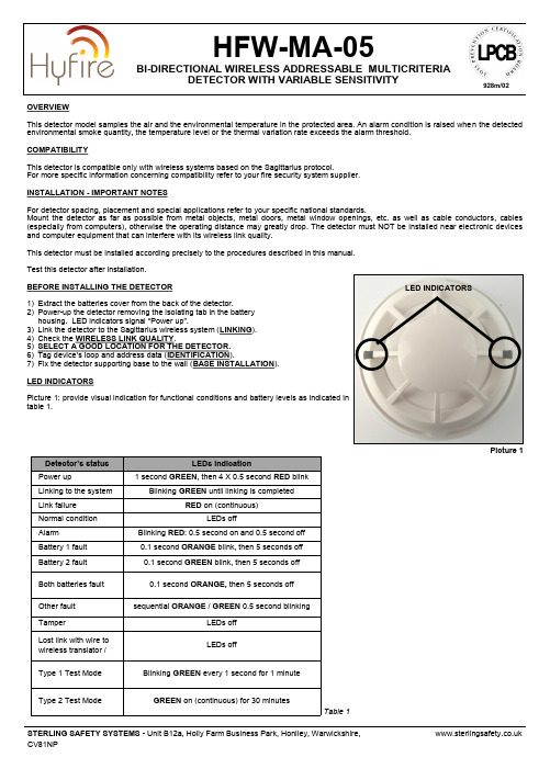
OVERVIEWThis detector model samples the air and the environmental temperature in the protected area. An alarm condition is raised when the detected environmental smoke quantity, the temperature level or the thermal variation rate exceeds the alarm threshold.COMPATIBILITYThis detector is compatible only with wireless systems based on the Sagittarius protocol.For more specific information concerning compatibility refer to your fire security system supplier.INSTALLATION - IMPORTANT NOTESFor detector spacing, placement and special applications refer to your specific national standards.Mount the detector as far as possiblefrom metal objects,metal doors, metal window openings, etc. as well as cable conductors, cables (especially from computers), otherwise the operating distance may greatly drop. The detector must NOT be installed near electronic devices and computer equipment that can interfere with its wireless link quality.This detector must be installed according precisely to the procedures described in this manual.Test this detector after installation.BEFORE INSTALLING THE DETECTOR1) Extract the batteries cover from the back of the detector.2) Power -up the detector removing the isolating tab in the battery housing. LED indicators signal “Power up ”.3) Link the detector to the Sagittarius wireless system (LINKING ). 4) Check the WIRELESS LINK QUALITY .5) SELECT A GOOD LOCATION FOR THE DETECTOR . 6) Tag device ’s loop and address data (IDENTIFICATION ).7) Fix the detector supporting base to the wall (BASE INSTALLATION ).LED INDICATORSPicture 1: provide visual indication for functional conditions and battery levels as indicated in table 1.HFW -MA -05BI -DIRECTIONAL WIRELESS ADDRESSABLE MULTICRITERIADETECTOR WITH VARIABLE SENSITIVITYLED INDICATORS Picture 1928m/02LINKINGrefer to the translator ’s or the Wirelex configuration software ’s literature):1) Move the link switch ’call it BLANK, since it carries no indication). LED indicators signal “system ” (picture 2).Linking is successful when: a) the translator indicates so (check translator ’s literature)ORb) the Wirelex software indicates so (check the Wirelex ’s literature).If linking is unsuccessful:2) Check if evident mistakes were made.3) Perform the LINKING RECOVERY .LINKING RECOVERY1) Take out both batteries from their holders2) Move alternatively the link switch to ON / BLANK five times (picture 2) 3) Move the link switch to ON4) Reinsert both batteries into their holders, oriented as per polarity marks5) Perform the LINKING procedure.DETECTOR SENSITIVITY SETTINGSDuring installation using the Wirelex software it ’s possible to set the smoke sensitivity and the heat class of the detector (see tables 4 and 5). Otherwise if the installation is performed manually through the translator keyboard, default setting will be applied.WIRELESS LINK QUALITYIt is possible to check wireless link quality between the detector and its linked -to translator or expander in this way:1) Move the link switch to the ON position.2) LED indicators will start blinking according to the following table:3) NOTE: Ensure the link switch is returned to the "BLANK" (operational) position on completion of testing.SELECT A GOOD LOCATION FOR THE DETECTORChoose for the detector a placement position that:- compliances with your specific standards- is reached by a strong wireless signal from its linked -to translator or expander module- is not interfered by environmental factors.IDENTIFICATIONFor identification purposes, analogue loop number and device ’address can be recorded on the plastic tag supplied with base (picture 3).base.**********************.ukL20-LMCXX -1400 (vA.2)Picture 3Assessment Device ’s indicationDuring the linking phase, the detector must be positionedclose to the aerial (within a few centimeters) of the translator or expander to which it is being linked. Picture 2 Link switchBASE INSTALLATIONFix the base to the wall with the provided screws (picture 4).DETECTOR PLACEMENT1)Install the batteries cover.2)Position the detector centrally on the baseensuring it is level.3)Rotate clockwise applying gentle pressure.The detector will drop into its keyed location.4)Continue to rotate clockwise a few degreesuntil the detector has fully engaged in thebase.5)When the detector is firmly engaged, checkthe alignment of the raised reference markson the detector and on the base (picture 5).DETECTOR LOCKINGTo lock the detector to the base, screw in the provided security screw; screw entry is locat-ed on the side of the detector’s base (picture 6).TAMPER DETECTIONWhen the detector is detached from the base a tamper message event is sent to the control panel.TESTINGTest this detector after installation.After each test reset the fire security system from the control panel, as per your control panel in-structions.TEST MODESTest modes make the HFW-MA-05 more reactive to aerosol stimulus; two test mode types are provided:Type 1 Test Mode -almost instantaneously alarm agent reactive.Type 2 Test Mode -makes the detector as reactive to smoke as an optical smoke detector, simulating it.TEST 1 - MAGNET TEST1) Hold a suitable magnet in correspondence of the indicated area (picture 7)2) LED indicator will signal “Type 1 Test Mode”3) Apply again the magnet in correspondence of the indicated area (picture 7)4) LED indicator will signal “Alarm”TEST 2 - AEROSOL TESTUse only suitable aerosol testers supplied by approved manufacturers.1) Hold a suitable magnet in correspondence of the indicated area (picture 7)2) LED indicator will signal “Type 1 Test Mode”3) By following its specific instructions, apply the aerosol test device to the detector4) Wait a few seconds5) LED indicator will signal “Alarm”TEST 3 - AEROSOL TESTUse only suitable aerosol testers supplied by approved manufacturers.1) Remotely activate the detector’s green LED from the Wirelex program2) LED indicator will signal “Type 2 Test Mode”3) By following its specific instructions, apply the aerosol test device to the detector4) Wait a few seconds5) LED indicator will signal “Alarm”TEST 4 - HEAT TESTUse only suitable heat test devices from approved manufacturers.1) By following its specific instructions, apply the heat test device to the detector.2) Wait a few seconds.3) LED indicator will signal “Alarm”.Picture 5Dust covers DO NOT providecomplete protection againstcontamination: detectorsshould be removed before construc-tion, major re-decoration or other dustproducing work is started.Dust covers MUST be removed beforethe system can be made operational.Picture 4Picture 6Picture 7MAINTENANCE - CLEANING1) Remove the detector from its base.2) Smoke entry areas and thermistor area: use asoft bristle brush to dislodge any obvious such as insects, spider webs, hairs, etc.3) Smoke entry areas and thermistor area: use a blow any remaining small particles away.4) damp, lint -free cloth to remove any surface film that later attract airborne contaminants.5) Install the detector onto its base again.6) Test the detector. MAINTENANCE - BATTERY REPLACEMENTWhen a low battery condition is indicated, both batteries must be changed altogether.During this procedure the linking switch must NOT be touched at all !1) Detach the detector from its base.2) Extract the batteries cover.3) Extract the batteries.4) Insert the new batteries into their holders, oriented as per polarity marks.5) Reinstall the batteries cover.6) Reinstall the detector onto its base.7) Test the detector.**********************.ukL20-LMCXX -1400 (vA.2)Table 3Table 4Table 5* When a low battery condition is indicated, both batteries must be changed for new cells. Lifespan of batteries indicated is subject to standard environmental conditions, default monitor settings and excellent link quality.** Check latest version of document TDS -LMCXX for further data, obtainable from your supplier.。
IFD云雾室型吸气式感烟火灾探测器地铁的应用

许多研究与文献已清楚指出,由于地铁厂站环境特殊,进出旅客数量庞大,疏散不易,加上厂站内高气流量变化、列车进出造成的震动、建筑装修的复杂化、使得传统的火灾探测器无法满足此特殊环境的需求,而空气采样式高灵敏度探测器是最适用于地铁厂站的火灾探测器,然而,接下来的问题是:•选用的设备能否运转于应有的高灵敏度?•运转于高灵敏度是否会带来误报的困扰?根据採用激光型探測器的用戶之运营相關單位指出,采用激光型空气采样式烟雾探测器于地铁的現場環境时,当灵敏度设定为0.08%obs/m时,会有误报的状况发生,经调降灵敏度至0.2%obs/m时,才减少误报情况。
然而,当设备的灵敏度设定为0.2%obs/m时,每个采样孔的灵敏度将降低至约3~5%(若设置15~20个采样孔时,如采用单区四管型,则灵敏度将更为迟钝),这样的灵敏度与传统点式探测器的灵敏度差不多,您能安心吗?而投入大笔预算采购高灵敏度探测器的意义还存在吗?因此,选择空气采样式高灵敏度探测器必须特别注意的是:1.设备能否真正运转在其应有的高灵敏度?2.运转在高灵敏度状态下会不会产生误报?上述两项要求对传统光电型探测器(如激光型)而言,是互相排斥的,所以其高灵敏度无法应用在实际环境。
除非决心在此传统单一光电技术之外,寻求突破的解答,…1968年,GE公司找到了答案-云雾室(Cloud Chamber)IFD云雾室型空气采样式极早期火灾探测器•具烟雾产生前即能发现火灾隐患的探测器•在高灵敏度状态也不因高灰尘而产生误报•不需汰换昂贵光电探测腔的低廉维护成本火灾的生命周期烟释放阶段火焰释放阶段热释放阶段火灾极早期阶段(热分解不可见粒子)火灾极早期阶段是指物质从被过度加热(Overheating)超过其材质可承受的临界点(即热分解点;Thermal Particulate Point),到氧化燃烧(Combustion)并开始产生碳烟的阶段。
在火灾发生的极早期阶段(此时尚无烟粒子产生)所出现的情况是热力的适度增加,进而产生大量的不可见次微米粒子(0.002μm;μ=10-6)。
FMST吸气式感烟火灾探测报警器操作说明1

FMST 吸气式感烟火灾探测报警器操作说明 FMSTDetector Power Sil/Iso Fire Time 显示模块Display ModuleAirflow Program 整机电源静音/隔离气流程序Silence Reset Test Isolate静音复位自检隔离火警2Fire2火警1Fire1行动PRE预警AUX.报警时间整机指示灯:绿灯亮起为正常运转 黄灯亮起为侦测机有故障 电源指示灯:绿灯亮起为正常运转黄灯亮起为电源有故障 静音/隔离指示灯:绿灯亮起为正常运行黄灯亮起为设备处于静音状态黄灯闪烁为设备处于隔离状态 气流指示灯: 绿灯亮起为正常运转,气流在正常范围内黄灯亮起为气流有故障,可能是气流过高管路可能断裂、气流量过低管路可能阻塞或是抽气泵失效程序指示灯: 绿灯亮起整机程序正常运行黄灯亮起为程序死机烟雾浓度指示灯: 首次开机有15分钟设备自学习时间,此时,16个红灯流动闪烁。
报警时间:LED 显示时间为最新报火警的时间。
预警级灯亮(AUX)当达到该报警级别,且超过一定的延时,该灯亮起,并伴有间断报警声。
行动级灯亮(PRE)当达到该报警级别,且超过一定的延时,该灯亮起,并伴有间断报警声。
火警Ⅰ级灯亮(Fire1)当达到该报警级别,且超过一定的延时,该灯亮起,并伴有不间断报警声。
火警Ⅱ级灯亮(Fire2)当达到该报警级别,且超过一定的延时,该灯亮起,并伴有不间断报警声。
静音键:按此键可以用来消除报警时蜂鸣器所发的声音。
当按下时指示灯长亮,整机处于消音状态。
复位键:连续按此键三次程序重新运行。
自检键:按此键设备进入自检状态,无须人工干预,自动诊断设备工作状态。
隔离键:按此键设备进入隔离状态。
被隔离后,设备不产生任何报警,且隔离指示灯亮。
现场处理办法当有作业人员在现场时发现有“预警”级和“行动”级报警时,应立刻查明报警原因并进行处理,消除烟源,待报警信号自动消除后,才能离开现场。
吸气式感烟火灾探测器系统操作手册

IFD Cirrus Pro极早期火警预警系统操作手册目录第一章一般操作 (1)第二章异常操作 (6)第三章查询 (9)第一節事件检视 (9)第二節历史曲线图 (11)第三節数据库查询 (12)第四節历史数据查询 (13)第五節图面打印 (14)第四章 CirrusPro控制器操作 (15)第一節组件选项 (15)第二節灵敏度设定 (16)第三節编辑文字 (16)第四節输入输出设定 (17)第五節管之进气流 (18)第六節保修信息 (18)第七節制造信息 (19)第八節清除事件线图 (20)第九節展示模式 (20)第五章数据设定 (21)第一節树状窗口操作 (21)第一項监控计算机 (22)第二項 F-NET (25)第三項区域 (30)第四項 CPD(CirrusPro控制器) (33)第二節图片窗口操作 (36)第一項新增 (36)第二項删除 (36)第三項更改属性 (37)第四項 CPD位置调整 (37)第六章登入 (39)第七章使用者管理 (40)第一節使用者权限 (40)第二節新增使用者 (41)第三節修改使用者 (41)第四節删除使用者 (42)第一章一般操作进入极早期火警预警系统, 屏幕显示如下:窗口说明:树状窗口极早期火警预警系统之数据为树状结构,以监控计算机图标 开始,第二层为区域侦测网络(F-NET) ,每一个区域侦测网络包含区域 (第三层),每一个区域包含极早期火警预警控制器(CPD) (最后一层)。
树状显示窗口如下:图示说明: 图控树状窗口 图片窗口讯息窗口 CPD 状态窗口监控计算机区域侦测网络(F-NET)区域极早期火警预警控制器(CPD)讯息窗口依CPD的状态显示该异常CPD之相关讯息。
图片窗口显示目前选定区域图片。
在树状窗口节点上按下鼠标左键, 即可快速切换至该区域或极早期火警预警控制器图片。
鼠标光标图标说明:鼠标游标在图面上移动时之图示。
当鼠标游标在图面时按下鼠标左键时之图标,此时移动鼠标可拖曳图面。
IFD火灾探测器安装及调试说明
真空泵引管 接口
云雾室
压强传感器 接口
云雾室
水位传感器 接口
水位传感器
云雾室
空气样品 过滤器
清洁空气 过滤器
云雾室
进水管
云雾室
LED光源 产生器 电源接口
LED光源 产生器
云雾室
内容
外观 内部结构 主板 云雾室 抽气泵 真空泵 水瓶 分解程序 一般故障发现与处理
机器数据储存
打开网络Байду номын сангаас项框,当选择‘发送 送设定讯息到单机上’ (Set detector network number)时
会出现一个 确认对话询 问你程序已 经重置,是 否确认要改 变设置,按 下【OK】即 可传送设置 信息到前端 设备。
在更改设置的后,数据需储存于机器中。
任何机器设定的更改必须下载至机器中,这必须从机器的选单中手动 完成,但如果关掉联机时,修改尚未储存会出现提醒讯息。 再有任何要关闭电脑程序动作时,如果有修改数据,显示屏幕会出现 提示(本设备设置已经改变,如果不把新设置发送到前端设备,修改 数据将会丢失,是否放弃修改):
主板
LED光电接收 器接口
主板
LED光源 發生器接口 水位传感器 接口
内容
外观 内部结构 主板 云雾室 抽气泵 真空泵 水瓶 分解程序 一般故障发现与处理
云雾室
固定螺丝
固定螺丝
云雾室
LED光电组件 接收器
注意:连接的时候一定要小心引脚
云雾室
电磁阀
云雾室
搜索连接于网络里的所有设备
2. 分配计算机端口位置
点击网 络 (Netw ork)
选择相 应的接 口 (CO M Port)
吸气式感烟火灾探测器系统操作手册
IFD Cirrus Pro极早期火警预警系统操作手册目录第一章一般操作 (1)第二章异常操作 (6)第三章查询 (9)第一節事件检视 (9)第二節历史曲线图 (11)第三節数据库查询 (12)第四節历史数据查询 (13)第五節图面打印 (14)第四章CirrusPro控制器操作 (15)第一節组件选项 (15)第二節灵敏度设定 (16)第三節编辑文字 (16)第四節输入输出设定 (17)第五節管之进气流 (18)第六節保修信息 (18)第七節制造信息 (19)第八節清除事件线图 (20)第九節展示模式 (20)第五章数据设定 (21)第一節树状窗口操作 (21)第一項监控计算机 (22)第二項F-NET (25)第三項区域 (30)第四項CPD(CirrusPro控制器) (33)第二節图片窗口操作 (36)第一項新增 (36)第二項删除 (36)第三項更改属性 (37)第四項CPD位置调整 (37)第六章登入 (39)第七章使用者管理 (40)第一節使用者权限 (40)第二節新增使用者 (41)第三節修改使用者 (41)第四節删除使用者 (42)第一章一般操作进入极早期火警预警系统, 屏幕显示如下:窗口说明:树状窗口极早期火警预警系统之数据为树状结构,以监控计算机图标开始,第二层为区域侦测网络(F-NET),每一个区域侦测网络包含区域(第三层),每一个区域包含极早期火警预警控制器(CPD)(最后一层)。
树状显示窗口如下:图示说明: 图控树状窗口 图片窗口讯息窗口 CPD 状态窗口监控计算机区域侦测网络(F-NET)区域极早期火警预警控制器(CPD)讯息窗口依CPD的状态显示该异常CPD之相关讯息。
图片窗口显示目前选定区域图片。
在树状窗口节点上按下鼠标左键, 即可快速切换至该区域或极早期火警预警控制器图片。
鼠标光标图标说明:鼠标游标在图面上移动时之图示。
当鼠标游标在图面时按下鼠标左键时之图标,此时移动鼠标可拖曳图面。
盛赛尔吸气式感烟火灾探测器设计使用手册
XI'AN SYSTEM SENSOR ELECTRONICS, LTD.
吸气式感烟火灾探测器设计使用手册
前言
本手册重点介绍了盛赛尔公司吸气式感烟火灾探测器的设计与使用方法,我们力求使 产品的信息做到最新、最准确,希望本手册能满足您对盛赛尔产品的了解。如有疑问或 需要了解进一步的产品信息,请与我们及时取得联系。
全新的西安盛赛尔电子有限公司新厂房位于西安高新技术产业开发区,占地面积 30 余亩,投资额 1000 万美元,新厂房完全按照现代化生产企业的布局而建,厂房内的布局更趋合理,完全满足了公司的 生产需求。公司将以“提供高质量的产品、合理的价格、及时交货及优质服务使用户满意”为服务宗旨, 愿与国内外火灾自动报警设备生产厂家和从事消防报警行业的单位以多种方式进行合作,共同开发国内 外市场。
现场需要进行适当调整,同时根据现场环境状况设置探测器的管路检测的控制阈值。需要注意同一种设置方式在不同的应用环 境及管路布置情况下其响应灵敏度及管路中气流速度会不同。一般而言在高大的空间里,由于高大空间对空气样本的稀释,设 备的响应灵敏度及响应时间会低于较小的空间。
一般的设计要求如下: • 最大单管长度不超过 100 米(一定要保证最末端采样孔到探测器的气流传输时间不了上表天花板高度限制,可以参考<10%一栏的数据。如果是“人”字坡顶,那么可以参 考快速反应栏的数据。
西安盛赛尔电子有限公司享有并保留一切著作权之专属权利,非经我公司同意,不 得对本手册部分或全部从事增删、改编、翻印或仿制之行为。
1
I56-1000-01C
公司简介
西安盛赛尔电子有限公司是世界 500 强之一的霍尼韦尔集团(HONEYWELL)的子公司美国盛赛尔公司 (SYSTEM SENSOR)在西安投资兴办的专业火灾探测器生产企业,是目前国内最大的火灾探测器专业生 产商,公司全套引进美国盛赛尔公司(SYSTEM SENSOR)的先进技术、工艺、管理系统、质量保证体系 和现代化的生产加工设备,生产各类火灾探测器及配套件产品,产品的质量、性能、技术指标均与美国 本部完全一致。公司产品已通过美国 UL 测试及中国国家消防电子产品质量监督检验中心的检验,主要 产品设计都获得了国家专利。公司已通过 ISO9000 国际认证(美国 UL 公司审核)及公安部消防产品合 格评定中心的 GBT19000 质量体系认证,获准使用 3C 认证标志。公司是 2000 年度中国消防电子产品质 量体系认证复查检验的首家唯一免检企业,2002 年再次获得唯一免检称号,并连续入选中国消防产业 30 强论坛单位。
吸气式感烟火灾探测器使用说明书(2)
吸气式感烟火灾探测器使用说明JTY-JXP01JTY-JXP02河南良大空间消防科技有限公司2020.3目录目录 (1)前言 (1)产品介绍 (2)产品简介 (2)功能特点 (3)技术参数 (3)功能 (4)指示灯 (4)应用场合 (4)操作说明 (7)操作面板 (7)指示灯说明 (8)按键功能 (8)LED显示 (9)操作方法 (11)接线端子功能说明 (11)前言感谢您购买本公司军巡铺牌系列吸气式感烟火灾探测器。
为使您从速了解本产品,本说明书中详细叙述了本产品的使用方法、日常维护保养等相关内容,请充分利用本说明书,谨记注意事项,避免因人为操作不当造成故障,以便更久地保持本产品的性能。
使用前,请务必阅读本说明书的有关内容。
本公司各类产品均经过严格的品管检验才出厂,您可放心使用,若发现任何困难或问题,请与本公司联系。
产品介绍产品简介军巡铺牌系列吸气式感烟火灾探测器是河南良大空间消防科技有限公司自主研发的新一代管路采样式、高灵敏度吸气式感烟火灾探测器。
主要用于高灵敏度烟雾探测的场所及高洁净、高大空间、高温、高湿或具有强电磁辐射等环境。
军巡铺牌系列吸气式感烟火灾探测器通过内部抽气设备把被监测区域的空气吸入激光采样检测室进行分析,判断是否发生火警,如有火警则给出声音提示,启动相应的继电器,记录相关信息。
功能特点●每管独立探测室、独立分区,灵敏度可调、风速上下限等参数,真正实现分区控制。
●可编程火警级别继电器输出,1个故障继电器输出。
●卡扣式外壳,安装方便快捷。
●单管最大采样长度100米,可根据现场情况灵活配置。
●可显示当前采集参数:烟雾值、风速流量等,4.5寸彩色液晶显示屏,清晰方便。
●高精度时钟能够准确记录报警时间、故障时间。
●预留上位机通信接口,方便远程控制。
技术参数●工作电压:DC24V,允许范围18V-36V●继电器输出:2A@30VDC;0.5A@125V AC●执行标准:GB15631-2008●联网方式:RS485接口●信息存储容量:火警记录999条,运行、操作记录999条●单管最大采样长度:100米●采样回路数目:JTY-JXP011个;JTY-JXP022个;●工作温度范围:-10︒C----55︒C●工作湿度范围:相对湿度10%----95%,无凝露●外形尺寸:JTY-JXP01330mm*220mm*110mm(长*宽*高)JTY-JXP02330mm*220mm*110mm(长*宽*高)●重量:3Kg 0.5Kg●外壳材质:铝合金●IP防护等级:IP30功能指示灯●火警指示灯:红色,有火警时点亮,正常熄灭。
- 1、下载文档前请自行甄别文档内容的完整性,平台不提供额外的编辑、内容补充、找答案等附加服务。
- 2、"仅部分预览"的文档,不可在线预览部分如存在完整性等问题,可反馈申请退款(可完整预览的文档不适用该条件!)。
- 3、如文档侵犯您的权益,请联系客服反馈,我们会尽快为您处理(人工客服工作时间:9:00-18:30)。
CIRRUS PRO火灾侦测器用户手册目录1.0简介 (2)1.1型号和设备 (3)2.0 定期检修 (4)2.1 定期检查 (4)2.1.1 每天检查 (4)2.1.2 三个月检查 (4)2.1.3 年度检查 (4)3.0 使用者指引 (5)3.1 面板指示和控制 (5)3.2 面板显示 (5)3.2.1 主功能选单 (7)3.2.2 实时图形表示 (7)3.2.3 单位/管显示 (8)3.2.4 事件讯息 (8)3.2.5 历史图形 (9)3.2.6 密码 (9)3.2.7 维修讯息 (10)4.0 侦错 (11)4.1 错误讯息列表 (11)4.2 侦测单元上的错误码 (11)5.0 侦测器规格 (12)1.0简介本手册详述了Cirrus Pro Series Aspirating Fire Detectors的安装、测试、服务以及使用方法。
背景众所皆知当材料过热时会产生比可见光波长还小的粒子,而且其数量远远超过在正常环境下存在的粒子数。
Cirrus Pro侦测器利用Wilson的云雾室理论来侦测火的早期及其它各阶段所产生的次微粒子。
经过过滤的空气样本经由离心风扇传送到侦测器,其中一部份被送入增湿器中。
在接近100%的相对湿度下,空气样本被吸入云雾室。
因为真空样本在迅速的膨胀和降温过程中,使水气凝结在小粒子表面而形成“云”。
因此,这些由温度变化产生的粒子而造成的“云”会被云雾室的测量系统侦测。
云的密度会以相称的粒子数量来表现。
侦测的结果是一个连续的讯号,其对应于粒子的浓度,且此讯号用来提供有4个顺序的警报。
Cirrus Pro侦测器有自我管理系统,会持续的监视其正常的操作。
任何问题会立即有面板灯号、蜂鸣器及失误继电器发出警告。
Cirrus Pro侦测器将失误数据、背景粒子浓度及事件数据储存在本机内存中,这些数据可以用选购的Cirrus窗口软件来存取及输出。
选购的面板显示器可以用来做结构的选项及显示全部的数据,面板显示器可以安装在侦测器上或装在远程,利用网络可监控到32个侦测器或面板显示器。
1.1涵盖的设备及机型Cirrus Pro 100 一个25mm外径采样管入口,采样管最多可到100mCirrus Pro 200 四个25mm外径采样管入口,四管总长最多可到200m,单一采样管最多可到100mCirrus Pro 200D 同Cirrus Pro 200,加内建编程显示器(参考RDP)Cirrus Pro 200SC,四个25mm外径采样管入口,有扫瞄功能,四管总长最多可到200m,单一采样管最多可到100mCirrus Pro 200DSC,同Cirrus Pro 200SC,,加内建编程显示器(参考RDP)RDP (Remote Display Panel) 远程编程显示器,多功能1/4VGA背板LCD显示及控制器2.0定期检查及维护Cirrus Pro侦测器能借助于回馈回路不断的调整自已的监控功能,以确保一个最低的程度的保养。
为确保持续正确的操作,本系统须依以下的频率检查。
●使用者每天检查●每三个月由Protec公司或其授权代表检查●当建物会影响系统操作的变更完成时●当设备的保护范围内有影响系统操作的变更完成时●在设备有故障的情况时●在任何警报发生后下列的叙述是依据一般的状况,由于各种应用的可能性的广泛范围,定期检查保养的频率须依情况调整。
2.1定期检查2.1.1每日检查以下各项必须由使用都每日执行●检查系统并明确其在良好的工作状态下●任何故障的指示应被纪录于系统日志中并调查●决定故障的程度及是否需要采取特殊行动(如火灾巡逻,检查任何的故障在报告之前都有被注意)2.1.2每季检查以下各项必须Protec公司或其授权代表每三个月(季)实行●检查事件日志并判断任何异常●用去离子的蒸馏水充填水壶●检查所有的管路都正确的连接且没有纠结●检查入口的完整●检查直流电源的电压●检查警报及取得水平是先前设定的●检查真空度(等级)●检查采样系统的气流读数●检查所有管路最远的取样点的运送时间●检查LCD的电流●检查云雾室的过滤器(滤网)必要时请更换●检查真空泵的风箱,必要时更换小心:不要轻视定期更换滤网,虽然用过的滤网显示可通过建议的气流量,但陷入的灰尘会造成次微米火灾粒子记忆值的增加而减低系统效能。
2.1.3每年检查以下各项必须由Protec公司其授权代表每12个月(年)实行●执行先前叙述约每季检查●检查流量(流体)电热调节器,必要时请清洁●检查真空泵风箱必要时更换●检查云雾室及其光学组件必要时请清洁3.用户指南3.1面板指示器及控制器所有的Cirrus Pro型号都有一个小控制盘,上面有6个LED的指示灯号及按钮。
指示灯号::分4个警报系统等级,先期警报及火灾1.2.3期,这些等级的设定点可以在PC上的委托选项中的灵敏性设定单元中测试。
电源指示灯亮表示电源正常,当远程电源故障时电源指示灯会闪烁,电源指示灯不亮表示设有电源提供此单元。
控制按钮:沉默—释放动作的警报继电器,且/或使内建蜂鸣器静音重设—实行沉默按钮的功能,且清除任何目前的火灾情况3.2面板显示器当启动时,显示器会显示网络上单元的数量。
显示器下方约文字相对应于显示器下方的按钮,持续按着按钮,其功能会自动的不断重复。
静音用来保持传统系统蜂鸣器静音。
按选单会列出网络上找到的单元上、下按钮移动选择的单元选择按钮接受目前反白的侦测器单元,要求状态并依型号不同显示以下窗口:显示目前采样管的粒子等级按选单会要求输入密码用+、一又Enter按钮来选择号码,低等级安全密码在生产时预先设定为123456 这是可以由显示器来更改的请见3,2,6当所有的数字都输入后按接受3.2.1主选单显示可接受的选项用”下”按钮移动至须要的选项按“选择”来移动选单上的选项,在此选单时按”离开”会回复到粒子等级显示须要重新输入密码以回到此主选单。
一般规则:上及下–在选单可接受的各选项中移动选择–改变反白选项的值移到下一个选单+及- --增加及减少高亮的值接受–储存改变于侦测器单元中有些改变在完全执行前须先重设离开–离开目前的选单,注意有些改变仍然保持在此显示器中,直到按了接受按钮后才会将改变送到侦测器单元中。
按钮持续的被按住–短时间后会自动重复其功能3.2.2实时图形显示约5分钟的目前粒子及警报等级的实时图形用+及-按钮来观查其它的采样管(如果有)3.2.3单元/管路、命名显示器接受各单元的命名,用上、下及编辑以选择要被编辑的命名。
用左、右及离开按录来选择单元,要改变一个字符,用+及-依下列次序来转动符号及字母。
编辑完成后,按离开回到单元/管路命名的显示屏当所有的命名都更正完成按接受将命名送到各单元中。
如果接受按钮没有被按过按离开以离开此选单且保持命名不变(编辑后)。
3.2.4事件日志事件日志储存单元中最后的128个事件最后的事件最先显示,按下一个以显示先前的事件按两者皆是改变只显示火灾事件按火改变显示器又显示故的事件。
按故障返回到显示所有的事件3.2.5历史曲线图历史曲线图显示10天的储存数据中3天的图形。
数据的储存量依记录期间发生的事件而有不同。
当火灾及早期警报发生时储存的数据量会增加。
3.2.6安全密码当开启此窗口时显示为0用+及-来增加或减少其值,并用选择(Sel) 加入另一个位数,最多可用9位数,第一位数不得为0。
当须要的数字显示时按下接受键立即更新此单元。
将此数记录起来是很重要的因为其不能从单元中取出。
按“离开”以离开此屏幕且不改变此密码3.2.7服务信息可接受的值泵压力 > 5.7psi电源电压 19到39VLED 电流 0.26到5.6T Ma空气流量 参照管路计算平均填充时间 一般为4到6天,依地方情况而定4.0故障发掘内部对故障的诊断监控可以正常的运作4.1故障列表以下列出可能的故障原因及其他码1.程序故障8水填充故障15单元失效2.内存损坏9.空气流动故障16扩张电路板故障3电源故障10内存过载17外部故障4没水11单元被隔离18电池故障5云雾室密封12供应电源太低19主要部份故障6真空故障13 Algotec故障20采样阻塞7 LED故障14Unit Cold故障21清洗阻塞22区域覆写功能可用故障代码可以用以下叙述取得4.2在侦测器单元上显示故障代码Cirrus Pro可以用故障LED的律动来表示目前的或最后一次故障的代码当此单元故障时,持续按住沉默键。
故障LED灯会亮5秒钟然后律动故障代码的次数。
当律代码完成时故障LED灯会再亮5秒钟,此代码会重复显示或显示其他的故障代码。
以上为LED显示的一个故障(故障代码4-缺水故障)以上为LED显示了两个故障代码(代码分别为3和4)多重故障时其故障代码会依其大小顺序显示。
此顺序会一直重复直到沉默按钮被释放了。
5.0侦测器规格依型号而不同的物理资料此处不列电源电压19-30V直流湿度10-95% Rrt无凝结温度0~38℃IP Rating IP30管路配件20mm接头管路末端末端阻塞螺丝管路内径19~25mm(外径25mm)警报指示灯早期警报,火灾1期,火灾2期,火灾3期其他指示灯电源:一般故障敏感度范围20k到3M个粒子敏感度范围10等级可程序所需的输入项目4个监控项目,隔离,静音及敏感度改变开路电压16V,最大应用电压30V最大开路电路电阻:1500Ω输出继电器:4个可程序的火灾继电器1个故障继电器4个扩充板上采权的4个增加/管路全部电源:交流电125V 0.3A直流电30V 1A,保持电流1A最大启动电压交流125V直流60V最大启动电流1A辅助(备用)电源:电压27.6V 电流300Ma电源故障输入:故障等级< 2.5V事件日志:128个事件以先入先出方式储存数据保留期:10天历史图形灵敏度设定:7天可程序设定,每天3个时区AlgoTec:环境学习,交互作用的判断使algorithm的软件连续监控环境背景的粒子等级并将侦测器的灵敏度及警报门坎作优化处理。
空气流量监控:监控空气流量故障的上下限。