宝马阀说明
API6D4”Z1A21C美标闸阀使用说明书

API6D4”Z1A21C美标闸阀使用说明书
DS/SYSM-Z-04-01 API6D4”Z1A21C美标闸阀其闸板在阀杆的带动下,沿阀座密封面作升降运动而达到启闭的目的。
1、压力级:150磅
2、使用温度:-29℃~425℃
3、适用介质:水、蒸汽、油品等非腐蚀性介质
4、流量系数Kv=817.8
5、最大关闭扭矩为32522 (N.㎜)
6、最大关闭力为295N
一、结构特点
1、阀体通道为全通径,流体阻力小。
2、介质可从闸阀二侧任意方向流过,不受介质流动方向的限制。
3、全开时密封面受冲蚀性较小,密封性能好。
二、维护保养
1、运输途中的维护
阀门在运输途中应注意要轻装轻卸,以防止法兰密封面磕碰损坏,应将密封面擦干净后再关闭。
要确保油漆、铭牌和法兰密封面的完好,现场要作好防雨、防尘工作。
2、保管中的维护
对入库的阀门,要认真擦拭、清洗阀门在运输过程中的积水和灰尘,对容易生锈的加工面、阀杆、密封面应涂上一层防锈剂或贴上一层防锈纸加以保护。
阀门进出口通道的封盖要封好,以免赃物进入。
对在运输中损坏、丢失的阀门零部件,应及时配齐。
3、运转中的维护
阀门在运转过程中要使阀门处于常年整洁、润滑良好、阀件齐全、正常运转的状态。
以达到开启灵活的目的,不允许在运行中对阀门进行敲打。
阀门关闭或开启不允许使用加长板手。
三、常见故障的防治。
BIFFI icon2000电动阀门操作手册
重要:
检查名牌上“环境温度范围”与外界环境温度一致。
2. 从执行机构上拆下联轴器
随机提供的轴套是装配在驱动轴套上,但可能没有加工。为了加工轴套,需把轴套从壳体上拆 下,同时拆下联轴器上的固定螺钉。
10
“ICON2000”电动执行机构
安装及维修手册
现在可以在衬套上加工出连接需要的轴孔。同样的步骤也用于维修。
重点:
重装轴套前,确认与阀杆配合公差正确。对螺纹连接轴套,须用螺纹规检 查,或将轴套旋入需驱动阀门的阀杆,检查其与阀杆没有过分磨擦。
2.1.2 重装内部零件:
建议用合适的溶剂清洗拆下零件,然后用压缩空气干燥,确认没有金属屑或异物,然后将所有 部件涂一层薄的润滑脂。(润滑脂牌号:见第 5 章)
11
用合适卡钳拆下卡环 拆下碳钢止推环; 取出衬套并按配合需要加工。
“ICON2000”电用合适的溶剂清洗拆下零件,然后用压缩空气干燥,确认没有金属屑,然后涂一层薄的润滑
脂。(润滑脂牌号:第一部分第四章) 按拆下时的相反顺序装配内部零件,然后安装到减速器上。如后描述。
Copyright by BIFFI Italia. All rights reserved. A tyco INTERNATIONAL LTD. COMPANY
12
“ICON2000”电动执行机构 安装及维修手册
注意:
除执行机构上安装的手轮和离合杆外,不要用其它工具(如铁棒、轮扳手、管 扳手等)操作手轮和离合杆,否则会对造成人身严重伤害和/或执行机构或阀门 的损坏。
火电厂汽轮机旁路阀说明及特点
德国BOMAFA旁路说明及结构型式、特点德国宝马阀介绍德国宝马阀公司是一家德国家族公司,创建于1919年,该公司在德国阀门领域有着非常好的业绩,公司以极高的产品质量和极优的售后服务而闻名遐迩。
BOMAFA的姊妹公司ASFA公司提供与阀门相配的气动或液压执行机构,BOMAFA 与ASFA一起,为用户提供整套的阀门系统。
BOMAFA公司总部设在西德,产品出口到世界各地,并为全球用户提供全方位的服务。
宝马阀公司设计、制造特种阀门,在电厂、石油、化工和其他工业领域中已积累了80多年经验,实践证明BOMAFA产品及其服务是真正值得信赖的,她为客户量体裁衣,提供充分考虑客户需求,基于客户的阀门解决方案。
宝马阀公司的产品范围包括蒸汽调节阀门,按客户要求设计的各种规格减温减压器、高低压汽机旁路系统、给水调节阀、汽机专用阀、安全阀、最小流量阀、锅炉启动阀、闸阀、孔板等,总之,宝马阀可提供以蒸汽、气体和水为介质的各种类型特种阀门。
宝马阀公司的宗旨是充分了解客户需求,确保产品设计完全满足客户。
因此,宝马阀不仅仅是一个阀门供货商,还是您理想的工程伴侣:与您共同考虑实际运行需要,这必然对运行人员的操作非常有益。
笼式阀芯系列高低压旁路阀体采用超宽的流线形设计:A.减少了介质的流通阻力,避免了介质发生相变时对阀体的侵蚀。
阀芯为套筒(笼式)结构,具有流阻小流通能力大,振动、噪声小的特点。
B、阀门按压差的大小采用不同的多级节流形式,这样,通过多级降压减轻了汽体对阀门的冲击和震动,降低了噪音。
同时也避免对阀口的冲蚀。
C、采用了镶装式分体阀座,杜绝了裂纹的产生。
阀门开启后温度急剧上升,但整个阀体的温升是不均匀的,阀座温升最快,阀体稍慢,温升后都要产生热变形,由于阀座与阀体的材质不同,热膨胀系数不同,导致变形不同步,传统阀门的阀座与阀体是焊接一体的,这时巨大的应力就产生了,加之震动的存在,裂纹就容易发生了。
鉴于此,德国宝马阀采用了镶装式分体阀座,杜绝了裂纹的产生。
AS-SERIES阀门说明书
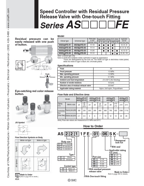
JIS SymbolFlow Direction Symbols on Body1ReleaseMade to Order(Refer to page 465 for details.)Refer to page 465 for details.Speed Controller with Residual Pressure Release Valve with One-touch FittingSeries AS FEResidual pressure can be easily released with one push of button.Eye-catching red color release button.How to OrderS y m b o lMeter-out typeMeter-in typeJ I S S y m b o lC o u r t e s y o f C M A /F l o d y n e /H y d r a d y n e ŀ M o t i o n C o n t r o l ŀ H y d r a u l i c ŀ P n e u m a t i c ŀ E l e c t r i c a l ŀ M e c h a n i c a l ŀ (800) 426-5480 ŀ w w w .c m a f h .c o mAS2201FE-01, AS2211FE-01AS2301FE-01, AS2311FE-01AS4201FE, AS4211FE AS4301FE, AS4311FEAS2201FE-02, AS2211FE-02AS2301FE-02, AS2311FE-02AS3201FE, AS3211FE AS3301FE, AS3311FELubricant: VaselineX12Ex.) AS2201FE-01-04SK-X12Throttle Valve (Without Check Valve)X214Ex.) AS2201FE-01-04SK-X214Ex.) AS2201FE-01-04SK-X21Note) Throttle valve is only compatible with the part no. of the meter-out type.F l o w r a t e (l /m i n (A N R ))E f f e c t i v e a r e a (m m 2)Inlet pressure: 0.5 MPaNumber of needle rotations F l o w r a t e (l /m i n (A N R ))E f f e c t i v e a r e a (m m 2)Inlet pressure: 0.5 MPaNumber of needle rotationsF l o w r a t e (l /m i n (A N R ))E f f e c t i v e a r e a (m m 2)Inlet pressure: 0.5 MPaNumber of needle rotationsF l o w r a t e (l /m i n (A N R ))E f f e c t i v e a r e a (m m 2)Inlet pressure: 0.5 MPaNumber of needle rotationsGrease-free (Seal: Fluorine Coating) +Throttle Valve (Without Check Valve)X21Needle Valve/Flow CharacteristicsBe sure to read before handling.Refer to front matters 58 and 59 for Safety Instructions and pages 412 to 414 for Flow Control Equipment Precautions.CautionMade to OrderNote 1)Not particle-freeNote 2)Throttle valve is only compatible with the part no. of the meter-out type.C o u r t e s y o f C M A /F l o d y n e /H y d r a d y n e ŀ M o t i o n C o n t r o l ŀ H y d r a u l i c ŀ P n e u m a t i c ŀ E l e c t r i c a l ŀ M e c h a n i c a l ŀ (800) 426-5480 ŀ w w w .cElbow type Meter-out typeUniversal type Meter-out typeMeter-in typeMeter-in typeNote 2) Meter-in type is black zinc chromate plated.Construction(2)C o u r t e s y o f C M A /F l o d y n e /H y d r a d y n e ŀ M o t i o n C o n t r o l ŀ H y d r a u l i c ŀ P n e u m a t i c ŀ E l e c t r i c a l ŀ M e c h a n i c a l ŀ (800) 426-5480 ŀ w w w .cElbow typeUniversal type(Hexagon widthacross flats)(Hexagon widthacross flats)Applicable tubing O.D. ødDimensionsNote 2)Reference dimensions of R thread after installation.Note 2)Reference dimensions of R thread after installation.DimensionsC o u r t e s y o f C M A /F l o d y n e /H y d r a d y n e ŀ M o t i o n C o n t r o l ŀ H y d r a u l i c ŀ P n e u m a t i c ŀ E l e c t r i c a l ŀ M e c h a n i c a l ŀ (800) 426-5480 ŀ w w w .c。
阀门说明书

驱动机构失效
1.连接键损坏脱落 2.锥销剪断
1.更换键 2.更换锥销
电动装置和气动装置故障
见“阀门电动装置说明书”和“阀门气动装置说明书”
7.保修
制造厂对阀门投入使用一年内负责保修,但不超过发货期 18 个月。在保修期内,因产品 质量原因均可免费修理或更换零件。
a.对夹蝶阀
2.3.1 普通碳钢阀门适用温度为-29℃~+425℃ 2.3.2 合金钢阀门适用温度-29℃~550℃ 2.3.3 不锈钢阀门适用温度为-196℃~+200℃
3.结构
3.1 蝶式止回阀基本结构见图 1
4.工作原理
蝶式止回阀靠介质顺流时的压力克服弹簧的扭力而开启,靠弹簧所产生的扭力矩而关闭, 再靠介质逆流时的压力产生的密封比压达到密封。
1.范围
本 说 明 书 包 括 了 公 称 通 径 DN15mm~500mm(1/2”~20”) 、 公 称 压 力 PN1.6MPa~10MPa(ANSI CLASS150~600)螺纹端、法兰端、对焊端和承插焊端连接的手动、 齿轮传动、电动和气动操作的二分体式(对分式)和三分体式(对夹式)的浮动球球阀和固定球球 阀。
6.可能发生的故障、原因及消除方法 见表 1
-1-
表 1 可能发生的故障、原因及消除方法
可能发生的故障
发生故障的原因
消除方法
阀瓣打不开或关不上
1.摇杆与销轴配合太紧或有 异物卡住
2.阀内有异物卡阻
1.检查配合情况 2.消除异物
阀门声响大、有振动
1.阀门安装位置离泵太近 1.重新安装合适位置 2.管道内介质流动压力不稳 2.消除压力波动
5.5 应安装在垂直管道上。
BOMAFA公司演示-闸阀
发电厂中控制阀门的操作控制模块
宝马阀的制造设备
宝马阀的制造设备
宝马阀的设计部门
ห้องสมุดไป่ตู้
设计人员在讨论设计方案
服务及维修
维修和保养各种类型的阀门 定期技术交流 现场服务 提供所有的备品备件
TüV质量认证证书
宝马阀基于客户的阀门解决方案
宝马阀质量体系控制
测试和检验 范围描述 操作试验 拉伸试验 冲击试验 硬度试验 着色渗透试验 磁粉探伤试验 X-射线检测 超声波测试 泄露试验 测试 标准 根据客户要求 EN 895 EN 875 EN 1043-1 EN 571-1 EN 1290 EN 1435 EN 1714 European Directive 97/23/EC European Directive 97/23/EC 测试 地点 内部 外部 外部 内部/外部 内部 内部 内部 内部 内部
石油行业
MEDOIL OMV Stora ENso Ruhr Oel Veba Oil Weller Pumpen …
化工行业
BASF AG Bayer AG Clariant Hindustan Fertilizer National Fertilise Paksaudi Fertilizer Prometal Thyssen Stahl Ticona …
蒸汽转换阀 安全控制阀 汽轮机专用阀 高/中压闸阀 减温器及蒸汽减温装置 气体阀门 特种阀门 高/中/低压文丘里喷嘴
宝马阀基于客户的阀门解决方案
宝马阀基于客户的阀门解决方案
典型发电厂的热力流程图
N L M C M L C C E D Boiler H Condensed Area G C M I
A. HP高压旁路系统
美标阀门型号说明
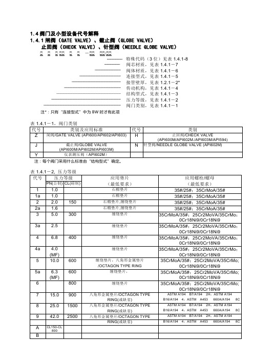
1.4阀门及小型设备代号解释1.4.1闸阀(GATE VALVE)、截止阀(GLOBE VALVE)止回阀(CHECK VALVE)、针型阀(NEEDLE GLOBE VALVE) - / 特殊代码(3位)见表1.4.1-8阀芯材质,见表1.4.1-7阀体材质,见表1.4.1-6连接型式,见表1.4.1-5接管壁厚,见表1.2.1-2*传动机构,见表1.4.1-4结构型式,见表1.4.1-3压力等级,见表1.4.1-2阀门类别,见表1.4.1-1 注*:只有“连接型式”中为BW时才有此项注:每个阀门采用什么标准由“结构型式”确定。
注: 每个阀门选用何种材料的垫片和螺栓、螺母由“阀体材料”确定。
对CL900.1500.2500三个等级的阀门,一般采用压力密封阀盖,此时“阀盖垫片”和“阀盖螺栓”项缺省。
等级1a、2a、3a、4a、5a适用于JB标准阀门。
注: 如果阀门的结构型式为“2”、“8”和“9”,即阀盖为压力密封阀盖,则该表中的“阀盖垫片材料”和“阀盖螺栓材料”栏缺省。
如果阀门的结构型式为“5”,则该表中的“阀杆填料”栏缺省。
表1.4.1-8,特殊代码1.4.2球阀(BALL VALVE)特殊代码(3位)见表1.4.1-8阀芯材质,见表1.4.2-2阀体材质,见表1.4.1-6连接型式,见表1.4.1-5接管壁厚,见表1.2.1-2*传动机构,见表1.4.1-4结构型式,见表1.4.2-1压力等级,见表1.4.1-2阀门类别:球阀/BALL VALVE,代号-Q1.4.3 旋塞阀(PLUG VALVE)阀芯材质,见表1.4.3-2阀体材质,见表1.4.1-6连接型式,见表1.4.1-5接管壁厚,见表1.2.1-2*传动机构,见表1.4.1-4结构型式,见表1.4.3-1压力等级,见表1.4.1-2阀门类别:旋塞阀/PLUG VALVE,代号-P1.4.4 蝶阀(BUTTERFLY VALVE)阀芯材质,见表1.4.4-2阀体材质,见表1.4.1-6连接型式,见表1.4.1-5接管壁厚,见表1.2.1-2*传动机构,见表1.4.1-4结构型式,见表1.4.4-1压力等级,见表1.4.1-2阀门类别:蝶阀/BUTTERFLY VALVE,代号-D1.4.5 疏水阀(STEAM TRAP VALVE)阀芯材质,见表1.4.5-2阀体材质,见表1.4.1-6连接型式,见表1.4.1-5结构型式,见表1.4.5-1压力等级,见表1.4.1-2阀门类别:疏水阀/STEAM TRAP VALVE,代号-S1.4.6 过滤器(STRAINER)阀体材质,见表1.2.1-3连接型式,见表1.4.1-5接管壁厚,见表1.2.1-2*结构型式,见表1.4.6-1压力等级,见表1.3.1-2阀门类别:过滤器(STRAINER),代号-T阀芯材质一般为304。
- 1、下载文档前请自行甄别文档内容的完整性,平台不提供额外的编辑、内容补充、找答案等附加服务。
- 2、"仅部分预览"的文档,不可在线预览部分如存在完整性等问题,可反馈申请退款(可完整预览的文档不适用该条件!)。
- 3、如文档侵犯您的权益,请联系客服反馈,我们会尽快为您处理(人工客服工作时间:9:00-18:30)。
以下是带快开功能的等量跟踪减温减压器阀门控制逻辑要求:一、阀门需要信号:1、阀门控制信号20-4mA.此信号用于控制阀门在没有跳车时,对阀门的调节。
2、透平抽气流量跟踪信号20-4mA(跳车指定位置信号):此信号来自抽气流量转换为阀门开启信号加上阀门当时开启的开度信号,具体说明如下:透平抽气跟踪流量信号=阀门目前开度+抽气流量信号抽气流量信号:透平抽气流量对应阀门的开度--由阀门特性曲线找到对应的点。
以2#阀门为例:由于阀门特性曲线为非线性结构,故而要以阀门当前的开度为基础作为相对零点,找到阀门相对应的开度信号,比如,当前阀门为30%,就要从特性曲线中找到相对应的流量百分比即:25%。
阀门数据表中显示阀门流量最大值可通过附件中的阀门数据表查找到,列如2#阀门为150T,。
然后找到这点之后,再把抽气流量,列如为30t,对应的流量百分比为20%最后透平抽气流量的流量百分比为,25%的基础上增加20%,也就是此时对应的流量百分比为45%,然后通过阀门特性曲线,寻找到阀门开度应为47%。
这是就需要把这个47%的阀位,转换成电信号20-4mA,作为“透平抽气流量跟踪信号”传递给阀门。
需要指出的是:抽气流量的数值具体从哪里得到,这是设计机组的时候应该就已经决定了的,需要咨询设计院。
我们的阀门只是被动接受信号,信号的来源跟阀门本身没有关系。
3、透平跳车信号(24V二进制开关量),阀门在汽机没有跳车时,这个信号为常闭信号;汽机跳车时,需要断开这个二进制信号。
具体信号来自汽机系统的什么地方,需要设计院确认。
4、阀门反馈信号(20-4mA),返回给DCS。
二、阀门常规调节控制逻辑要求:阀门在平常调节时,需要所有的信号在20-4mA的范围以内,阀门控制信号以及透平抽气流量跟踪信号均不能低于4mA,否则阀门速度控制器,将会出现报警信息。
阀门在平常调节时,要求透平跳车信号为常闭信号,需要DCS 给予阀门+24V的电压。
阀门在平常调节时,阀门控制信号以及透平抽气流量跟踪信号均需要输入到阀门内,此时阀门只受“阀门控制信号”控制。
三、阀门快开控制逻辑要求:阀门在快开前,阀门控制信号以及透平抽气流量跟踪信号均需正常给予阀门快开时,需要给阀门一个跳车信号,即:透平跳车信号(24V二进制开关量)为失电状态断开。
此时阀门受透平抽气流量跟踪信号控制,具体参见附件中的阀门速度控制器说明。
四、阀门快开结束逻辑要求:阀门在快开结束之后,需要把跳车信号恢复,此时阀门再次受到“阀门控制信号”控制。
阀门在从跳车状态恢复到调节状态的过程中,逻辑上要求在这个转换过程中实现阀门无扰动。
德国宝马阀电子式等量跟踪快开减温减压阀控制说明德国宝马阀电子式等量跟踪快开减温减压阀气动执行机构的“等量跟踪快开电子控制柜”集快速和精确调节功能为一体。
完成透平正常运行时,快开减温减压阀对透平抽气流量的等量跟踪;透平跳机时,快开减温减压阀对透平抽气流量的无扰动等量快开切换。
该“等量跟踪快开电子控制柜”主要部件为电子控制元件.它能够根据透平不同的抽气流量工况,在透平跳机时,通过控制柜内部的比例阀和3/2 通电磁阀之间自动控制切换,完成快开减温减压阀对透平抽气流量的无扰动等量快开切换。
一“等量跟踪快开电子控制柜”部件描述:具有调节功能及等量跟踪快开功能的减压阀PV 的气动控制系统详见No.3L11538/C 图减压阀PV 气动控制系统主要包括以下几个部分:1,一个容纳电子控制器件的柜子(柜子装于气动执行器附近的单独支架上)2,一个空气供应站(部件10)包括过滤器,减压阀和压力表3,一个电动-气动比例阀(部件20)用于控制减温减压阀PV 4,两个压力表(部件40)5,一个带有消音器(部件61)的3/2 通电磁阀(部件60)用作快开减压阀门PV 的先导操作6,消音器(部件75)的两个气动3/2 通阀(部件70,71)用于减压阀PV 的快开操作7,一个等量跟踪电子控制箱8,一个带有安全阀和止回阀的储气罐(部件80),储气罐是按照减压阀PV 两个完整冲程的要求设计的.9,一个双动作气动气缸PZ16C-400/56X55 D (部件90)用于调节及快开减压阀PV10,一个阀位变送器(部件91)用于反馈信号(4-20mA),阀位变送器安装于气动执行器上(部件90)二,“等量跟踪快开电子控制柜”控制描述压缩空气在空气站(件10)内经过滤并减压压至3.5bar(g)。
快开减温减压阀PV 正常调节控制:快开减温减压阀PV 在正常开关调节,是由DCS 输出20-4mA 信号给等量跟踪快来电子控制柜的电-气比例阀,及阀位开度反馈20-4mA 信号给电-气比例阀来完成。
与此同时,通过透平的蒸汽流量对应的阀门开度,转化为20-4mA 信号也是通过DCS送至等量跟踪快开电子控制柜,该信号在透平正常运行时,不会影响到减压阀的正常调节,此时,3/2 通电磁阀带电。
快开减温减压阀PV 正常调节是通过对比阀位设定值和阀位的实际值,得到一个控制偏差值.此偏差通过等量跟踪快开电子控制柜的电-气比例阀(部件20),使快开减温减压阀PV 将调整开度状态直至偏差为零,完成调节功能。
阀位实际值是通过将超声波位置检测系统(部件91)集成至气动执行机构(部件90)的方式把一个20-4mA 电流信号(对应于0-100%行程)反馈给等量跟踪快开电子控制柜(速度控制器).20mA=阀门关闭(0%);4mA=阀门开启(100%)最终设定值/实际值通过的对比可以使减压阀精确的开启在预设的位置上.蒸汽透平跳机(快开减温减压阀PV 快开):汽轮机跳机的二进制信号是由DCS 传送给等量跟踪快开电子控制柜的.根据程序的设定,当3/2 通电磁阀(部件60;快开用先导阀)处于失电且压缩空气通过气动3/2 通阀(部件70,71)放空.此时,气动3/2 通阀(部件70,71)为失气状态。
快开减温减压阀PV 借助压缩空气储罐(部件80)内的压缩空气打开,当快开减温减压阀PV 即将到达蒸汽透平流量设定值时,电控箱内的程序(使用前减压阀必须校准)将会使3/2 通电磁阀(部件60)重新带电及两个气动3/2 通阀(部件70,71)复位.同时,减压阀PV 将由电-气比例阀(部件20)控制并调整余下的蒸汽流量升至设定值,而不会超调.减压阀PV 在汽轮机紧急停机时快开时间约为0.5 秒.随后中控系统(DCS)将在通过汽轮机的蒸汽流量的设定值(20-4mA)和电-气比例阀(部件20)的协助下完成控制任务.当来自DCS的蒸汽透平跳机信号复位时,电控箱(速度控制器)内的程序将再次改变,快开减温减压阀PV 将像最初时一样能够被来自DCS 的阀位输入的20-4mA 信号,及阀位开度反馈给等量跟踪快开电子控制柜的电-气比例阀20-4mA 信号,通过等量跟踪快开电子控制柜的电-气比例阀完成正常的快开减温减压阀PV 调节控制. 27x0201,27x0202pieces 1Tag No.: CustomerDimen- C Englisch XNo. sion M1.011.02 DN C/M1.03 PN C/M1.04 mm C1.05 C1.06 C1.07 C/M1.08 barg / °C C1.09 bar M 220 931.101.11 °C C1.12 bar/a C/M2.012.02 C2.03 t/h C2.04 Pressure p1 bar/a C2.05 Temp. t1 °C C2.06 Speed w1 m/s C/M2.07 Outlet Pressure p2 bar/a C2.08 Temp. t2 °C C2.09 Speed w2 m/s C/M2.10 Wet steam ts °C M2.11 m³/h M2.12 C/M2.13 sec. C3.013.02 mm M3.03 M3.04 C X3.05 Mounting position C/M v o h3.06 B C/M3.07 C/M3.08 M3.09 C/M X3.10 Pieces. M 1 13.11 mm M 97 90 403.12 Pieces. M3.13 M X3.14 M X3.15 M X3.16 M X3.17 M X3.18 M X3.19 M X3.20 M X 23.21 Pieces M3.22 M3.23 M 13.24 M3.25 M3.26 M 1 1803.27 M3.28 M X3.29 C/M 1.7383 1.7383 1.73833.30 C/M3.31 M 1.7383 1.4923 1.49233.32 M 1.49233.33 M Grafit Grafit Grafit3.34 M3.35 M3.36 85 dB(A) C/M3.37 M kg kg3.38 X M 6.7 t/h 140 bar(a) 1583.39 M DN 25 PN 250 Number3.40 Connection M3.41 Acceptance acc. to PED 97/23/EC L Category others4.014.024.034.044.054.064.07 Revision4.08 04.094.104.11 M to be filled in by BOMAFA4.12 C to be filled in by customer4.13 License of Customer Signature: DatePhone:+49 / 2327 / 992-0 Fax:+49 / 2327 / 31443E-Mail: info@bomafa.deD - 44866 Bochum Hohensteinstr. 52BOMAFA Armaturen GmbHDate256 2011-03-11Modifications Row NameFirm PhoneBOMAFAShi/BaumgardtRemarksQuantity Waterpr. Watertemp.Design data: Press./Temp. bar/°C 155/172injection waterWater studDesignNoise emission (insulated) Wall thickness of the outlet piping must be total at least 15 mm weight of the Valve without Actuator with actuatorPacking material for: Stem Seat bush Cover lockCool. water Flange 1.5415 Warm up stud Draining con. Stud 1.7335 Insert Seat bush PlugPerforated bush Orifice Plug nutMaterialsInlet Body OutletActuatorMulti-turn actuator Flap actuator Thrust actuatorHydraulic actuator Pneumatic actuator HandwheelAdditionalBellow Preheater conn. stud Cooler body/Pro.PlateBonnet / Protective grating Dome for nozzle Nominal width DomeSwelling steam delivery over Seat bush to cooler body to center nozzleWater injection Center nozzle Seat bu./Ann. Cap/Lance Cooler body for nozzlesSteam filter single doubleSilencer at valve outlet Number of orifice Number of perf. Plate Throttle labyrinth Pressure relief inserts Seat bush as throttle bush Number of throttle bush Red.- steps total Plug type Flatplug Parabolic plug Perforated plugSealing of the stem relief space piston rings packing of pure graphiteValve plug fully relieved partly relieved with control spindleValve seat armoured nitride dynamic double seatSeat bush removable removable/self-sealing weldedValve insert cramped self-sealing with swelling steam con.Fixed point (Valve) Bracket at body Rubber-bounded BaseDrain-/ Warm up-/ Swelling steam - stud/pip. DN 25 DN 40 PipingDesign Seat diameter Stroke Plug stem diameterWelding stud at the body Inlet Outlet Dished boiler endBody construction Cast steel Forged steel WeldmentActuator design Body size 5Leakrate ANSI/FCI Class IV RangeabilityConstruction Angle design Straight-way design Z-designValve type Dim. Sheet R4629-MValve Data Control ValveNominal width of body connection Inlet 150 Outlet 250Floating time for full stroke Adjustment Quick-opening 0,5 Quick-closingKvs - ValueType of characteristic line equal % linear X Special designFluidic parameter Kv - Value444 444 44441 41 4166,68 60,66 69,20535 540inlet 99.1 89.3 99.1540110 70 1506Medium Steam Steam SteamCapacityclosedOperating Data Case No. 1 2 3 4Ambience condition5p actuator design openDesign data (assumed): Pressure / Temp. 104/545 49/510Material: Welding end / Piping 1.7380 1.7380Seal design for flangeWelding groove / Flange design BW BWx xNominal pressure 420 63PipingDesign Data Inlet Outlet Inlet OutletCustomer order n.: EntriesValveNominal width 150 250 12Cr1MoV 15CrMoGDimension of pipe connectionInstallation Series 27X0201 Meike chemical industry Type of Valves Reducing valve with quick-opening function Item 1.1 Data Sheet Valves Com. No.:Test pressure (T = RT )CoatingModuleBOMAFA standard: Feidozink - S zink dust paint grey mattSpindle vertical / horizontal (v/h)) actuator above / under (a/u)) Inl. horiz./above/under(h/a/u)Connecting coefficient V = 1 Evaluation group (in accordance with DIN EN ISO 5817 a.2517)Direction fo flowLeakage / Rangeability Leakage∆OD ODpieces 1Tag No.: CustomerDimen- C Englisch XNo. sion M1.011.02 DN C/M1.03 PN C/M1.04 mm C1.05 C1.06 C1.07 C/M1.08 barg / °C C1.09 bar M 220 931.101.11 °C C1.12 bar/a C/M2.012.02 C2.03 t/h C2.04 Pressure p1 bar/a C2.05 Temp. t1 °C C2.06 Speed w1 m/s C/M2.07 Outlet Pressure p2 bar/a C2.08 Temp. t2 °C C2.09 Speed w2 m/s C/M2.10 Wet steam ts °C M2.11 m³/h M2.12 C/M2.13 sec. C3.013.02 mm M3.03 M3.04 C X3.05 Mounting position C/M v o h3.06 B C/M3.07 C/M3.08 M3.09 C/M X3.10 Pieces. M 1 13.11 mm M 90 80 403.12 Pieces. M3.13 M X3.14 M X3.15 M X3.16 M X3.17 M X3.18 M X3.20 M X 23.21 Pieces M3.22 M3.23 M 13.24 M3.25 M3.26 M 1 1803.27 M3.28 M X3.29 C/M 1.7383 1.7383 1.73833.30 C/M3.31 M 1.7383 1.4923 1.49233.32 M 1.49233.33 M Grafit Grafit Grafit3.34 M3.35 M3.36 85 dB(A) C/M3.37 M kg kg3.38 X M 17.7 t/h 140 bar(a) 158 3.39 M DN 50 PN 250 Number3.40 Connection M3.41 Acceptance acc. to PED 97/23/EC L Category others4.014.024.034.044.054.064.07 Revision4.08 04.094.104.11 M to be filled in by BOMAFA4.12 C to be filled in by customer4.13 License of Customer Signature: DatePhone:+49 / 2327 / 992-0 Fax:+49 / 2327 / 31443E-Mail: info@bomafa.deD - 44866 Bochum Hohensteinstr. 52BOMAFA Armaturen GmbHDate256 2011-03-11Modifications Row NameBOMAFAShi/BaumgardtRemarksQuantity Waterpr. Watertemp.Design data: Press./Temp. bar/°C 155/172injection waterWater studDesignNoise emission (insulated) Wall thickness of the outlet piping must be total at least 15 mm weight of the Valve without Actuator with actuatorPacking material for: Stem Seat bush Cover lockCool. water Flange 1.5415 Warm up stud Draining con. Stud 1.7335 Insert Seat bush PlugPerforated bush Orifice Plug nutMaterialsInlet Body OutletActuatorMulti-turn actuator Flap actuator Thrust actuatorHydraulic actuator Pneumatic actuator HandwheelAdditionalBellow Preheater conn. stud Cooler body/Pro.PlateBonnet / Protective grating Dome for nozzle Nominal width DomeSwelling steam delivery over Seat bush to cooler body to center nozzleWater injection Center nozzle Seat bu./Ann. Cap/Lance Cooler body for nozzlesSteam filter single doubleSilencer at valve outlet Number of orifice Number of perf. Plate Throttle labyrinth Pressure relief inserts Seat bush as throttle bush Number of throttle bush Red.- steps total Plug type Flatplug Parabolic plug Perforated plugSealing of the stem relief space piston rings packing of pure graphiteValve plug fully relieved partly relieved with control spindleValve seat armoured nitride dynamic double seatSeat bush removable removable/self-sealing weldedValve insert cramped self-sealing with swelling steam con.Fixed point (Valve) Bracket at body Rubber-bounded BaseDrain-/ Warm up-/ Swelling steam - stud/pip. DN 25 DN 40 PipingDesign Seat diameter Stroke Plug stem diameterWelding stud at the body Inlet Outlet Dished boiler endBody construction Cast steel Forged steel WeldmentActuator design Body size 5Leakrate ANSI/FCI Class IV RangeabilityConstruction Angle design Straight-way design Z-designValve type Dim. Sheet R4629-MValve Data Control ValveNominal width of body connection Inlet 150 Outlet 350Floating time for full stroke Adjustment Quick-opening 0,5 Quick-closingKvs - ValueType of characteristic line equal % linear X Special designFluidic parameter Kv - Value310 310 31013 13 13535 540inlet 99.1 89.3 99.1540103 70 1506Medium Steam Steam SteamCapacityclosedOperating Data Case No. 1 2 3 4Ambience condition5p actuator design openDesign data (assumed): Pressure / Temp. 104/545 49/510Material: Welding end / Piping 1.7380 1.7380Seal design for flangeWelding groove / Flange design BW BWx xNominal pressure 420 63PipingDesign Data Inlet Outlet Inlet OutletCustomer order n.: EntriesValveNominal width 150 450 12Cr1MoV CSDimension of pipe connectionInstallation Series 27X0202 Meike chemical industry Type of Valves Reducing valve with quick-opening function Item 2.1 Data Sheet Valves Com. No.:Test pressure (T = RT )ModuleBOMAFA standard: Feidozink - S zink dust paint grey mattSpindle vertical / horizontal (v/h)) actuator above / under (a/u)) Inl. horiz./above/under(h/a/u)Connecting coefficient V = 1 Evaluation group (in accordance with DIN EN ISO 5817 a.2517)Direction fo flowLeakage / Rangeability Leakage∆OD ODasfa/Datenblatt/Pneumatic actuator (BOMAFA).doc Page 1 / 1Data Sheet ActuationSpecificationCom No.:27x0201,27x0202Type of Actuator: Pneumatic Item: 0101 Manufacturer: asfa Supplier: BOMAFA02 Type of Actuator: PZ16C-500/56 x 85 D Opening Power: 81000 N Closing Power: 81000 N Stroke: 85 mm03 Operating Characteristics Air Opens X Spring Closes Air closes X Spring Opens04 General Data Diaphragm Piston X Single-Acting Double-Acting X05 Eff. Area: 1963.50 cm²Spring Range: - bar Air Supply Pressure: 5 to 7 bar(g)06 Hand pump Top Side Without X07 Energy Failure Act. open Closed locked X08 Stroke Time: Normal: 15 to 20 sec. Quick-Opening: 0.5 sec. Quick-Closing: sec.Proportional valve (system of protection: IP 65; explosion protection: EEx nA II T4)09 Manufacturer: Norgren Type No.: VP601010 Case material Aluminium X Stainless steel Single-Acting Double-Acting X11 Signal Transmission: 4 to 20 mA bar Open direction 4 mA Close direction 20 mA12 Electr. connection size Connector13 Mounting unit14 Construction: With Pressure Gauges Without Pressure Gauge XPosition Transmitter (ultrasonic; system of protection: IP 67; explosion protection: II 1/2 G EEx d IIB + H2 T6)15 Manufacturer: Balluff Type No.: BTL5 (2 wire type; mounted in the actuator)16 Signal Transmission 4 to 20 mA Volt Valve open 4 mA Valve Closed 20 mALimit Switch17 Manufacturer: Type No.: Quantity:18 Type Pneum. Electr.-Mech. Inductive ContactOutput Valve Open Valve Closed19 Mechanical Position Indication Mechanical Valve Lift Stop from to mm20 Pipes: Ø12x1 and Ø38x2 (stainless steel)2122 other components (mounted in a cabinet which must be installed separately beside the pneumatic actuator)23 - 1 piece air filter regulator (adjusted at 5.0 bar (g)) with gauge (type 67CFR; manufacturer: Fisher-Rosemount;24 body material: aluminium; pneum. connection size: ¼‖ NPT)25 - 1 piece non return valve26 - 2 pieces 2/2 way valve (pneumatically; for locking in case of an air failure; type 8290; manufacturer: Asco)27 - 2 pieces pressure gauge28 - 1 piece 3/2 way solenoid valve (pilot valve for quick-opening; 24 V DC; IP 66; explosion protection EEx d II C T6; type: 327;29 manufacturer: Asco; body material: stainless steel; pneum. connection size: ¼‖ NPT; electrical connection size: ½‖ NPT)30 - 2 pieces 3/2 way valve (type 58D-56-RA and 58D-86-RA; manufacturer: MAC Valves)31 - 2 pieces silencer32 - 1 piece air tank (size: 90 liters) with non return valve and safety valve (for the quick-opening of the valve)33 - 2 pressure hoses (for the connection between the actuator and the cabinet)34 The electronic control box with the controlling of the valve (Speed Controlic; with explosion protection EEx d) is in35 our scope of supply.36 to line 05: valve action with 5.0 bar(g), max. pressure: 7.0 bar(g)ProcessingName: Phone DateH. Cordruwisch 992-280Modifications: No. Line Date Name:1 34, 35 H. Cordruwisch2Bomafa Armaturen GmbH 3D-44866 Bochum Hohensteinstr. 52 4Phone: +49 2327/992-0 Fax: +49 2327/31443 527x0201,27x0202Page 1 / 3 Functional description 2010-08-05Functional description and components of the pneumatic control system (Speed Controlic) Pneumatic control system for one Reducing Valve 27x0201,27x0202 (with Speed Controlic forcontrolled quick-opening and locking function)Drawing No. 3L 11975/AThe pneumatic control system for the Reducing Valve 27x0201,27x0202 consists mainly of thefollowing subassemblies:1.) 1 piece cabinet to house the pneumatic components (the cabinet is mounted beside thepneumatic actuator on a separate rack):- 1 piece air supply station (item 10) consisting of filter, pressure reducing valve and gauge.- 1 piece non return valve (item 11).- 1 piece electro-pneumatic proportional valve (item 20) with silencer (item 22) for the purpose of the controlling of the Reducing Valve 27x0201,27x0202.- 2 pieces pneumatically operating 2/2 way valves (item 30) for the purpose of lockingof the Reducing Valve 27x0201,27x0202.- 2 pieces pressure gauges (item 40).- 1 piece electrically operating 3/2 way solenoid valve (item 60) with silencer (item 61) as pilot operation for the purpose of quick-opening of the Reducing Valve 27x0201,27x0202.- 2 pieces pneumatically operating 3/2 way valve (item 70 and item 71) with silencer (item 75) for the purpose of quick-opening of the Reducing Valve 27x0201,27x0202. 2.) 1 piece air pressure tank NG 90 ltr. (item 80) with safety valve and non return valve (item 81). The air tank is designed for one to two complete strokes of the Reducing Valve 27x0201,27x0202.3.) 1 piece double-acting pneumatic cylinder PZ16C-500/56x85 D (item 90) for the purposeof controlling and quick-opening the Reducing Valve 27x0201,27x0202.4.) 1 piece position transmitter (item 91) for the feedback signal (4 to 20 mA). The position transmitter is mounted in the pneumatic actuator (item 90).5.) 1 piece electronic control box (Speed Controlic).The electronic control box is mounted beside the cabinet on the separate rack. Functional description of the control systemThe existing pressure air is filtered in the air supply station (item 10) and the pressure is reduced to 5.0 bar (g). This filtered pressure air is distributed to the electro-pneumatic proportional valve (item 20), to the pneumatically operating 2/2 way valves (item 30), to the electrically operating 3/2 way solenoid valve (item 60; pilot valve for quick-opening) and via non return valve (item 81) to the air tank (item 80). Page 2 / 3 Functional description 2010-08-05Controlling of the Reducing Valve 27x0201,27x0202:If there is to be any adjusting operation on the Reducing Valve 27x0201,27x0202 in the openingor closing direction, a set point value for the positioning of the Reducing Valve 27x0201,27x0202is fed in as a current signal of 20 to 4 mA (corresponds 0 to 100 % stroke), coming from theDistributed Control System (DCS), to the electronic control box (Speed Controlic) on thebeside the pneumatic actuator.Also the set point value for the steam flow over the turbine as a 20 to 4 mA current signal is fedin from the DCS into the electronic control box (Speed Controlic) without having influence onthe normal controlling of the Reducing Valve.The 3/2 way solenoid valve (item 60) is simultaneously energized with a continuous voltage.Comparison of the set point value for the positioning and the actual value of the Reducing Valve 27x0201,27x0202 can produce a control deviation. In response to this deviation, a controlsignal (4 to 20 mA) is admitted by the electronic control box (Speed Controlic) to the electropneumatic proportional valve (item 20). This causes re-adjustment of the Reducing Valve 27x0201,27x0202 until the deviation becomes zero.The actual value is fed back as a current signal of 20 to 4 mA (corresponds 0 to 100 % stroke)to the electronic control box (Speed Controlic) by means of the ultrasonic position measuringsystem (item 91) integrated in the pneumatic actuator (item 90).20 mA = valve close (0%)4 mA = valve open (100%)Permanent set point/actual value comparison by way of the electronic control box (Speed Controlic) now causes the Reducing Valve to exactly stay in their predetermined position. Steam Turbine Trip (controlled quick-opening of the Reducing Valve 27x0201,27x0202): The binary signal of the turbine trip comes from the Distributed Control System (DCS) to theelectronic control box (Speed Controlic) on the rack beside the pneumatic actuator. By the program in the electronic control box (Speed Controlic) now the electrically operating 3/2 waysolenoid valve (item 60; pilot valve for quick-opening) is de-energized and air pressure is vented out from the pneumatically operating 3/2 way valves (item 70 and item 71). As a result,the pneumatically operating 3/2 way valves (item 70 and item 71) get de-energized and theReducing Valve 27x0201,27x0202 opens with the help of the pressurized air in the pressure airtank (item 80). But without the electronic control box (Speed Controlic) the Reducing Valve now would overshoot over the set point value of the steam turbine flow and opens to 100%.So, shortly before the Reducing Valve 27x0201,27x0202 reaches the set point value of thesteam turbine flow, the program in the electronic control box (Speed Controlic) - which hadbe calibrate for the first operation of the Reducing Valve - energized the 3/2 way solenoid valve(item 60) again. Therefore also the both pneumatically operating 3/2 way valves (item 70 anditem 71) are energized gain. Additional the controlling of the Reducing Valve 27x0201,27x0202is taken over again by the proportional valve (item 20) that now readjusts the rest up to the endof the set point value of the steam flow, without overshooting. The Reducing Valve 27x0201,quick-opens in case of a steam turbine trip in a time of (for example) approx. 0.5 seconds (see the diagram at the end of the description).27x0202,Page 3 / 3 Functional description 2010-08-05The Controlling can be done now by the Distributed Control System (DCS) with the help of theset point value for the steam flow over the turbine (20 to 4 mA) and the electro-pneumatic proportional valve (item 20).After the signal of the steam turbine trip from the Distributed Control System (DCS) is no longer present, the program in the electronic control box (Speed Controlic) is changed again.Now the Reducing Valve 27x0201,27x0202 can be driven, as in the beginning, with the set pointvalue for the positioning (20 to 4 mA) the Distributed Control System (DCS).Locking of the Reducing Valve 27x0201,27x0202 (air supply failure):If the air pressure in the pneumatic system falls below approx. 4 bar(g), the 2/2 way pneumatically operating valves (item 30) are no further activated. As a result the Reducing Valve 27x0201,27x0202 is blocked in his last position.General referencesThe current pressure values can be read from the pressure gauges at the filter/reducer or atthe pressure gauges (item 40).Reference regarding maintenance and commissioning is made to the attached operation &maintenance instructions.Exemplary diagram of the controlled quick-opening with the Speed Controlic204060801000 0,2 0,4 0,6 0,8 1 1,2 1,4 1,6 1,8 2Time [sec.]Stroke [%]Quick-opening set value in % Speed Controlic in %pieces 1 Tag No.: CustomerDimen- C Englisch XNo. sion M1.011.02 DN C/M1.03 PN C/M1.04 mm C1.05 C1.06 C1.07 C/M1.08 bar/°C C1.09 bar M1.101.11 °C C1.12 bar/a C/M2.012.02 C2.03 t/h C2.04 Pressure p1 bar/a C2.05 Temp. t1 °C C2.06 Speed w1 m/s C/M2.07 Outlet Pressure p2 bar/a C2.08 Temp. t2 °C C2.09 Speed w2 m/s C/M2.10 Wet steam ts °C M2.11 m³/h M2.12 C/M2.13 sec. C3.013.02 mm M3.03 M3.04 C √3.05 Mounting position C/M V3.06 A C/M3.07 C/M3.08 M3.09 C/M X3.10 Pieces. M3.11 mm M 20 20 163.12 Pieces. M3.13 M3.14 M3.15 M X3.16 M X3.17 M X3.18 M X3.19 M3.20 M X 13.21 Pieces M3.22 M3.23 M3.24 M3.25 M3.26 M3.27 M X3.28 M X X3.29 C/M 20G 20 20G3.30 C/M3.31 M X35CrMo17 X35CrMo17 X35CrMo173.32 M3.33 M Grafit Grafit Grafit3.34 M3.35 M3.36 85 dB(A) C/M3.37 M kg kg3.38 M t/h bar °C3.39 M DN PN Number3.40 Connection M3.41 Acceptance acc. to PED 97/23/EC L Category others4.014.024.034.044.054.064.07 Revision4.08 04.094.104.11 M to be filled in by BOMAFA4.12 C to be filled in by customer4.13 License of Customer Signature: DateData Sheet Valves Com. No.:29,020Type of Valves Injection Valve Item 1.2Installation Series 27X0201 Meike chemical industryCustomer order n.: EntriesValveNominal width 25 25Dimension of pipe connectionPipingDesign Data Inlet Outlet Inlet OutletNominal pressure 250 250OD x OD xSeal design for flangeWelding groove / Flange designMaterial: Welding end / PipingDesign data (assumed): Pressure / Temp. 155/173 155/173p actuator design openAs to the calculation of strength, a temperature increase of 5°C has been taken into considerationAmbience conditionTest pressure (T = RT )Water Water2 3 4WaterOperating Data Case No. 1 5closedMedium156 160Capacity 9.11586.7 4.26inlet 140 138 14250 50 50158 150 150Kvs - ValueType of characteristic line equal % √linearFluidic parameterQuick-closingKv - ValueSpecial designFloating time for full stroke Adjustment Quick-openingValve Data Control ValveNominal width of body connection Inlet OutletValve type Dim. SheetInl. horiz./above/under(h/a/u)Direction fo flowConstruction Angle design Straight-way design Z-designLeakrateSpindle vertical / horizontal (v/h)) actuator above / under (a/u))RangeabilityActuator design Body sizeBody construction Leakage vBody construction Cast steel Forged steel WeldmentWelding stud at the body Inlet Outlet Dished boiler endDesign Seat diameter Stroke Plug stem diameterDrain-/ Warm up-/ Swelling steam - stud/pip. PipingFixed point (Valve) Bracket at body Rubber-bounded BaseValve insert cramped self-sealing with swelling steam con.Seat bush removable removable/self-sealing weldedValve seat armoured nitride dynamic double seatValve plug fully relieved partly relieved with control spindleSealing of the stem relief space piston rings packing of pure graphitePlug type Flatplug Parabolic plug Perforated plugPressure relief inserts Seat bush as throttle bush Number of throttle bush Red.- steps total Silencer at valve outlet Number of orifice Number of perf. Plate Throttle labyrinthSteam filter single doubleWater injection Center nozzle Seat bu./Ann. Cap/Lance Cooler body for nozzlesSwelling steam delivery over Seat bush to cooler body to center nozzleAdditionalBellow Preheater conn. stud Cooler body/Pro.PlateBonnet / Protective grating Dome for nozzle Nominal width DomeActuatorMulti-turn actuator Flap actuator Thrust actuatorHydraulic actuator Pneumatic actuator HandwheelCool. water stud Warm up stud Draining con. StudInsert Seat bush PlugPerforated bush Orifice Plug nutPacking material for: Stem Seat bush Cover lockMaterialsInlet Body OutletCoating BOMAFA standard: Feidozink - S zink dust paint grey mattConnecting coefficient V = 1 Evaluation group (in accordance with DIN EN ISO 5817 a.2517)Noise emission (insulated) Wall thickness of the outlet piping must be total at least 15 mm weight of the Valve without Actuator with actuatorinjection water Quantity Waterpr. Watertemp.Water stud Design data: Press./Temp. bar/°CDesignModule。