基于8051单片机的数字钟[附图+源码+中英文文献]
80C51单片机数字钟

(二)使用DS1302实现时钟一、实验原理:二、详细程序:/***********时钟,显示:时、分、秒;年,月,日。
可调时,使用1302**************/ /*********************2011,4,17***********************//********************* *****************************/#include<reg51.h>#include<intrins.h>#define uchar unsigned char#define uint unsigned intsbit sclk=P2^1;sbit rst=P2^2;sbit io=P2^3;sbit ACC0=ACC^0;sbit ACC7=ACC^7;sbit CLKPIN = P1^6;sbit DIPIN = P1^3;sbit k1=P1^1;sbit k2=P1^2;sbit k3=P1^0;uchar miao,fen,year,month,day,shi,shi_shi,shi_ge,fen_shi,fen_ge,miao_shi,miao_ge,year_shi,year_ge,month_shi,month_ge,day_shi,day_ge;uchar s_shi,s_fen,s_miao; //转换进制时用uchar sfen,sshi,smiao; //调整分\时\秒uint num1,num2,num3,num4;uchar code riqi[]={0x11,0x04,0x17};//ss_year=0x10,ss_month=0x04,ss_day=0x17;void delay(){uchar x,y;for(x=110;x>0;x--)for(y=60;y>0;y--);}void delay1(uint z){uint x,y;for(x=z;x>0;x--)for(y=110;y>0;y--);}void transbit(bit d){ DIPIN = d;_nop_();_nop_();CLKPIN = 1;_nop_();_nop_();CLKPIN = 0;_nop_();_nop_();CLKPIN = 1;}void transbyte(unsigned char d){ unsigned char i;for(i=0;i<8;i++){ if((d&0x1) == 0x1)transbit(1);elsetransbit(0);d>>=1;}}unsigned char code NUMCODETAB[]={0xFC,0x60,0xDA,0xF2, //数字0,1,2,30x66,0xB6,0xBE,0xE0, //数字4,5,6,70xFE,0xF6,0x00,0x02, //数字8,9,字符空格,字符-0x9C,0xCE,0x9E,0x8E}; //字符C,字符P,字符E,字符F void transram(n1,n2,n3,n4,n5,n6,n7,n8) //显示程序{unsigned char buf;buf=0x00;buf=NUMCODETAB[n1];transbyte(buf);buf=NUMCODETAB[n2];transbyte(buf);buf=NUMCODETAB[n3];transbyte(buf);buf=NUMCODETAB[n4];transbyte(buf);buf=NUMCODETAB[n5];transbyte(buf);buf=NUMCODETAB[n6];transbyte(buf);buf=NUMCODETAB[n7];transbyte(buf);buf=NUMCODETAB[n8];transbyte(buf);delay();}void DS1302_Write(uchar D){ //DS1302写入函数uchar i;for(i=0;i<8;i++){io=D&0x01;sclk=1;sclk=0;D=D>>1;}}uchar DS1302_Read(){ //DS1302读出函数uchar TempDat=0,i;for(i=0;i<8;i++){TempDat>>=1;if(io) TempDat=TempDat|0x80;sclk=1;sclk=0;}return TempDat;}void wt_sb(uchar addr, uchar date) //DS1302单字节写入函数{rst = 0;sclk = 0;rst = 1;DS1302_Write(addr); // 写地址DS1302_Write(date); // 写1Byte数据sclk = 1;}uchar rd_sb(uchar addr) //DS1302单字节读出函数{uchar date;rst = 0;sclk = 0;rst = 1;DS1302_Write(addr);date=DS1302_Read();sclk = 1;rst = 0;return date;}void SetTime(uchar ss_miao,uchar ss_fen,uchar ss_shi) //时间设置函数{wt_sb(0x80,ss_miao&0x7f);wt_sb(0x82,ss_fen&0x7f);wt_sb(0x84,ss_shi&0xbf);}void set_riqi(){wt_sb(0x8c,riqi[0]);wt_sb(0x88,riqi[1]&0x1f);wt_sb(0x86,riqi[2]&0x3f);}void charge_mode(){wt_sb(0x90, 0xa6); //一个电阻,一个二极管充电}void DecToBCD() //二-十进制转换函数{s_shi=(((sshi)/10)<<4)+((sshi)%10);s_fen=(((sfen)/10)<<4)+((sfen)%10);s_miao=((smiao/10)<<4)+((smiao)%10);}void key_set(){if((k1==0)|(k2==0)) //判断是否有调整时间键按下{if (k1==0) //调分delay1(2); //消抖if(k1==0){while(!k1); //等待松手sfen++;if(sfen==60)sfen=0;}}if (k2==0) //调时{delay1(2);if(k2==0){while(!k2);sshi++;if(sshi==24)sshi=0;s_shi=((sshi/10)<<4)+(sshi%10);}}DecToBCD(); //十进制转换为BCD码SetTime(s_miao,s_fen,s_shi);//修改时间}if(k3==0){delay1(2);if(k3==0){while(!k3);transram(year_shi,year_ge,11,month_shi,month_ge,11,day_shi,day_ge);delay1(2000);}}}void rd_ntime() //读取当前时间{uchar temp;temp=rd_sb(0x81); //secondmiao=((temp&0x7f)>>4)*10+(temp&0x0f);miao_shi=miao/10;miao_ge=miao%10;temp=rd_sb(0x83); //minutefen=((temp&0x7f)>>4)*10+(temp&0x0f);fen_shi=fen/10;fen_ge=fen%10;temp=rd_sb(0x85);shi=((temp&0x3f)>>4)*10+(temp&0x0f); //hourshi_shi=shi/10;shi_ge=shi%10;}void read_ndate(){uchar temp;temp=rd_sb(0x87);day=((temp&0x3f)>>4)*10+(temp&0x0f); //dayday_shi=day/10;day_ge=day%10;temp=rd_sb(0x89);month=((temp&0x1f)>>4)*10+(temp&0x0f); //monthmonth_shi=month/10;month_ge=month%10;temp=rd_sb(0x8d);year=((temp&0xff)>>4)*10+(temp&0x0f); //yearyear_shi=year/10;year_ge=year%10;}void main(){charge_mode();set_riqi();while(1){rd_ntime();read_ndate();transram(shi_shi,shi_ge,11,fen_shi,fen_ge,11,miao_shi,miao_ge);key_set();}}三、硬件电路:。
单片机制作数字钟(含万年历、秒表功能)
数字钟、万年历制作(基于单片机)电路原理图:程序://********************20131206****数字钟程序#pragma SMALL#include <reg51.h>#include <absacc.h>#include <intrins.h>//********************************************************* *********编译预处理void display(unsigned char *p); //显示函数,P为显示数据首地址unsigned char keytest(); //按键检测函数unsigned char search(); //按键识别函数void alarm(); //闹钟判断启动函数void ftion0(); //始终修改函数void ftion1(); //闹钟修改函数void ftion3(); //日期修改函数void cum(); //加1修改函数void minus(); //减1修改函数void jinzhi(); //进制修改函数void riqi(); //日期void stopwatch(); //秒表函数//********************************************************* *******函数声明sbit P2_7=P2^7;//********************************************************* *******端口定义unsigned char clockbuf[3]={0,0,0};unsigned char bellbuf[3]={0,0,0};unsigned char date[3]={1,1,1}; //日期存放数组unsigned char stop[3]={0,0,0};unsigned char msec1,msec2;unsigned char timdata,rtimdata,dtimdata;unsigned char count;unsigned char *dis_p;unsigned char or; //12进制控制标志unsigned char ri; //日期显示控制标志位unsigned char mb; //秒表控制标志位bit arm,rtim,rhour,rmin,hour,min,sec,day,mon,year; //定义位变量//********************************************************* *****全局变量定义void main(){unsigned char a;or=0; //12进制修改标志清零ri=0;mb=0;P2_7=0;arm=0;msec1=0;msec2=0;timdata=0;rtimdata=0;count=0;TMOD=0x12;TL0=0x06;TH0=0x06;TH1=(65536-10000)/256;TL1=(65536-10000)%256;EA=1;ET0=1;ET1=1;TR0=1;TR1=0;dis_p=clockbuf;while(1){a=keytest();if(a==0x78) //判断是否有键按下{display(dis_p);if(arm==1) alarm();}else{display(dis_p);a=keytest();if(a!=0x78){a=search();switch(a){case 0x00:ftion0();break;case 0x01:ftion1();break;case 0x02:cum();break;case 0x06:jinzhi();break;case 0x03:riqi();break;case 0x04:ftion3();break;case 0x05:minus();break;case 0x07:stopwatch();break;case 0x09:TR1=1;break;case 0x0a:TR1=0;break;case 0x0b:stop[0]=0;stop[1]=0;stop[2]=0;break;default:break;}}}}}//********************************************主函数【完】void display(unsigned char *p){unsigned char buffer[]={0,0,0,0,0,0};unsigned char k,i,j,m,temp;unsigned char led[]={0x3f,0x06,0x5b,0x4f,0x66,0x6d,0x7d,0x07,0x7f,0x6f};buffer[0]=p[0]/10;buffer[1]=p[0]%10;buffer[2]=p[1]/10;buffer[3]=p[1]%10;buffer[4]=p[2]/10;buffer[5]=p[2]%10;if((sec==0)&&(min==0)&&(hour==0)&&(rmin==0)&&(rhour==0)&&( day==0)&&(mon==0)&&(year==0)) //没有修改标志,正常显示{for(k=0;k<3;k++){temp=0x01;for(i=0;i<6;i++){P0=0x00; //段选端口j=buffer[i];P0=led[j];P1=~temp; //位选端口temp<<=1;for(m=0;m<200;m++);}}}else //若有修改标志,则按以下标志分别显示{if(sec==1||day==1){P1=0x1f;i=buffer[5];P0=led[i];for(m=0;m<200;m++);P1=0x2f;j=buffer[4];P0=led[j];for(m=0;m<200;m++);}if(min==1||rmin==1||mon==1){P1=0x3b;i=buffer[2];P0=led[i];for(m=0;m<200;m++);P1=0x37;j=buffer[3];P0=led[j];for(m=0;m<200;m++);}if(hour==1||rhour==1||year==1) {P1=0x3e;i=buffer[0];P0=led[i];for(m=0;m<200;m++);P1=0x3d;j=buffer[1];P0=led[j];for(m=0;m<200;m++);}}}//**********************************LED显示函数【完】unsigned char keytest(){unsigned char c;P2=0x78; //检测是否有键按下c=P2;c=c&0x78;return(c);}//******************************************键盘检测函数【完】unsigned char search(){unsigned char a,b,c,d,e;c=0x3f;a=0; //行号while(1){P2=c;d=P2;d=d&0x07;if(d==0x03){b=0;break;} //列号else if(d==0x05){b=1;break;}else if(d==0x06){b=2;break;}a++;c>>=1;if(a==5){a=0;c=0x3f;}}e=a*3+b;do{display(dis_p);}while((d=keytest())!=0x78);return(e);}//***********************************************查键值函数【完】void alarm(){if((clockbuf[0]==bellbuf[0])&&(clockbuf[1]==bellbuf[1])){P2_7=1;rtim=1;if(count==10){count=0;P2_7=0;arm=0;rtim=0;}}}//****************************************闹钟判断启动函数【完】void ftion0(){TR0=0;rhour=0;rmin=0;dis_p=clockbuf;rtimdata=0;timdata++;switch(timdata){case 0x01:sec=1;break;case 0x02:sec=0;min=1;break;case 0x03:min=0;hour=1;break;case 0x04:timdata=0;hour=0;TR0=1;break;default:break;}}//*********************************************时钟设置函数【完】void ftion1(){if(TR0==0) TR0=1;sec=0;min=0;hour=0;dis_p=bellbuf;timdata=0;rtimdata++;switch(rtimdata){case 0x01:rmin=1;break;case 0x02:rmin=0;rhour=1;break;case 0x03:rtimdata=0;rhour=0;arm=1;dis_p=clockbuf;break;default:break;}}//*********************************************闹钟设置函数【完】void ftion3(){if(TR0==0) TR0=1;day=0;mon=0;year=0;dis_p=date;timdata=0;rtimdata=0;dtimdata++;switch(dtimdata){case 0x01:day=1;break;case 0x02:day=0;mon=1;break;case 0x03:mon=0;year=1;break;case 0x04:dtimdata=0;year=0;dis_p=clockbuf;break;default:break;}}//*************************************************日期修改函数【完】void minus(){if(sec==1){if(0==clockbuf[2]) clockbuf[2]=59;else clockbuf[2]--;}else if(min==1){if(0==clockbuf[1]) clockbuf[1]=59;else clockbuf[1]--;}else if(hour==1){if(or==0) //判断进制{if(0==clockbuf[0]) clockbuf[0]=23;else clockbuf[0]--;}if(or==1){if(1==clockbuf[0]) clockbuf[0]=12;else clockbuf[0]--;}}else if(rmin==1){if(bellbuf[1]==0) bellbuf[1]=59;else bellbuf[1]--;}else if(rhour==1){if(or==0){if(bellbuf[0]==0) bellbuf[0]=23;else bellbuf[0]--;}if(or==1){if(bellbuf[0]==1) bellbuf[0]=12;else bellbuf[0]--;}}else if(day==1){if(date[2]==1) date[2]=31;else date[2]--;}else if(mon==1){if(date[1]==1) date[1]=12;else date[1]--;}else if(year==1){if(date[0]==1) date[0]=99;else date[0]--;}}//*************************************减1修改功能函数【完】void cum(){if(sec==1){if(59==clockbuf[2]) clockbuf[2]=0;else clockbuf[2]++;}else if(min==1){if(59==clockbuf[1]) clockbuf[1]=0;else clockbuf[1]++;}else if(hour==1){if(or==0) //判断进制{if(23==clockbuf[0]) clockbuf[0]=0;else clockbuf[0]++;}if(or==1){if(12==clockbuf[0]) clockbuf[0]=1;else clockbuf[0]++;}}else if(rmin==1){if(bellbuf[1]==59) bellbuf[1]=0;else bellbuf[1]++;}else if(rhour==1){if(or==0){if(bellbuf[0]==23) bellbuf[0]=0;else bellbuf[0]++;}if(or==1){if(bellbuf[0]==12) bellbuf[0]=1;else bellbuf[0]++;}}else if(day==1){if(date[2]==31) date[2]=1;else date[2]++;}else if(mon==1){if(date[1]==12) date[1]=1;else date[1]++;}else if(year==1){if(date[0]==99) date[0]=0;else date[0]++;}}//*************************************加1修改功能函数【完】void jinzhi(){if(or==0) or=1;else or=0;}//***********************************进制修改控制函数【完】void riqi(){if(ri==0){dis_p=date;}if(ri==1){dis_p=clockbuf;}ri++;if(ri==2) ri=0;}//********************************日期控显示函数【完】void stopwatch(){if(mb==0){dis_p=stop;mb=1;}else{mb=0;dis_p=clockbuf;}}//************秒表**********秒表**********秒表函数【完】void clock() interrupt 1{EA=0;if(msec1!=0x14) msec1++; //6MHz晶振定时10mselse{msec1=0;if(msec2!=100) msec2++; //定时1selse{if(rtim==1) count++; //闹钟启动标志计时10smsec2=0;if(clockbuf[2]!=59) clockbuf[2]++;else{clockbuf[2]=0;if(clockbuf[1]!=59) clockbuf[1]++;else{clockbuf[1]=0;if(or==0){if(clockbuf[0]!=23) clockbuf[0]++;else{clockbuf[0]=0;if((date[1]==1)||(date[1]==1)||(date[1]==1)||(date[1]==3)||(date[ 1]==5)||(date[1]==7)||(date[1]==8)||(date[1]==10)||(date[1]==12)){if(date[2]!=30) date[2]++;else{date[2]=1;if(date[1]!=11) date[1]++;else{date[1]=1;date[0]++;}}}if((date[1]==4)||(date[1]==6)||(date[1]==9)||(date[1]==11)){if(date[2]!=29) date[2]++;else{date[2]=1;if(date[1]!=11) date[1]++;else{date[1]=1;date[0]++;}}}if(date[1]==2){if((((date[0]%4==0)&&(date[0]%100!=0))||(date[0]%400==0))){if(date[2]!=28) date[2]++;else{date[2]=1;if(date[1]!=11) date[1]++;else{date[1]=1;date[0]++;}}}else{if(date[2]!=27) date[2]++;else{date[2]=1;if(date[1]!=11) date[1]++;else{date[1]=1;date[0]++;}}}}}}if(or==1){if(clockbuf[0]!=12) clockbuf[0]++;else{clockbuf[0]=0;if((date[1]==1)||(date[1]==1)||(date[1]==1)||(date[1]==3)||(date[ 1]==5)||(date[1]==7)||(date[1]==8)||(date[1]==10)||(date[1]==12)){if(date[2]!=30) date[2]++;else{date[2]=1;if(date[1]!=11) date[1]++;else{date[1]=1;date[0]++;}}}if((date[1]==4)||(date[1]==6)||(date[1]==9)||(date[1]==11)){if(date[2]!=29) date[2]++;else{date[2]=1;if(date[1]!=11) date[1]++;else{date[1]=1;date[0]++;}}}if(date[1]==2){if((((date[0]%4==0)&&(date[0]%100!=0))||(date[0]%400==0))){if(date[2]!=28) date[2]++;else{date[2]=1;if(date[1]!=11) date[1]++;else{date[1]=1;date[0]++;}}}else{if(date[2]!=27) date[2]++;else{date[2]=1;if(date[1]!=11) date[1]++;else{date[1]=1;date[0]++;}}}}}}}}}}EA=1;}//*******************************定时器0中断函数【完】void miaobiao() interrupt 3{TH1=(65536-10000)/256;TL1=(65536-10000)%256;if(stop[2]!=99) stop[2]++;else{stop[2]=0;if(stop[1]!=59) stop[1]++;else{stop[1]=0;if(stop[0]!=59) stop[0]++;else stop[0]=0;}}}//***********************************定时器1中断函数【完】。
基于8051的数码管时钟设计

单片机课程设计论文——基于8051的数码管时钟设计学生:侯国义201105310147祝清德201105310146指导教师:2012年7月2日摘要本设计是基于8051单片机,以keil和proteus作为相应的开发软件进行的设计开发,实现了8051控制下的数码管显示时钟。
本文从系统功能、设计原理等方面进行介绍。
关键词:8051,可调时钟,动态扫描,数码管。
一、系统组成及功能介绍1.基本原理此次设计主要是应用单片机来设计电子时钟,硬件部分主要分以下电路模块:显示电路用8个共阴数码管分别显示,通过动态扫描进行显示,从而避免了译码器的使用,同时节约了I/0端口,使电路更加简单。
单片机采用8051系列,这种单片机应用简单,适合电子钟设计。
利用单片机定时器完成计时功能,定时器0计时中断程序每隔50ms 中断一次并作一次计数,定时1s 到时,秒变量加1,同理再判断是否1min 钟到了,再判断是否1h 到了。
为了将时间在LED 数码管上显示,可采用静态显示法和动态显示法,由于静态显示法需要译码器,数据锁存器等较多硬件,可采用动态显示法实现LED 显示,通过对每位数码管的依次扫描,使对应数码管亮,同时向该数码管送对应的字码,使其显示数字。
由于数码管扫描周期很短,由于人眼的视觉暂留效应,使数码管看起来总是亮的,从而实现了各种显示。
2.系统功能1.在8位数码管上显示时间(日期、星期),显示格式“时时-分分-秒秒(年-月-日)”。
2.按键可选择显示时间或日期以及进行对应调整。
3.整点报时:每当整点时通过扬声器发出声音进行报时。
4.日历功能:能对年,月,日,星期进行显示,分辨平年,闰年以及各月天数,并自动调整。
3.系统框图系统组成框图8051单片机按键输入部分晶振和复位数码管显示部分二、硬件设计1.原理图(1)8051最小系统模块采用上电按钮复位电路:首先经过上电复位,当按下按键时,R1与R2分压,RST为高电平形成复位,同时电解电容被电路放电;按键松开时,VCC对电容充电,充电电流在电阻上,RST依然为高电平,仍然是复位,充电完成后,电容相当于开路,RST为低电平,单片机芯片正常工作。
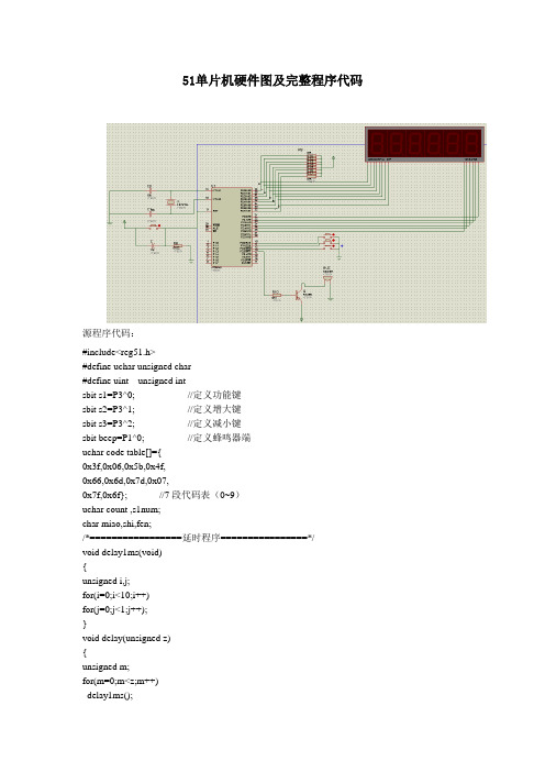
51单片机电子时钟硬件图及完整程序代码
delay(10);
P2=0xdf; //片选秒十位
P0=table[s/10];//显示小时十位
delay(10);
P2=0xff; //关闭所有片选位
}
/*=================初始化函数================*/
void init()
delay(10);
P2=0xf7; //片选分十位
P0=table[f/10]; //显示分十位
delay(10);
P2=0xff; //关闭所有片选位
}
/*=================时显示程序================*/
void displayshi(uchar s)
{
P2=0xef; //片选小时个位
sbit beep=P1^0; //定义蜂鸣器端
uchar code table[]={
0x3f,0x06,0x5b,0x4f,
0x66,0x6d,0x7d,0x07,
0x7f,0x6f};//7段代码表(0~9)
uchar count ,s1num;
char miao,shi,fen;
/*=================延时程序================*/
void delay1ms(void)
{
unsigned i,j;
for(i=0;i<10;i++)
for(j=0;j<1;j++);
}
void delay(unsigned z)
{
unsigned m;
for(m=0;m<z;m++)
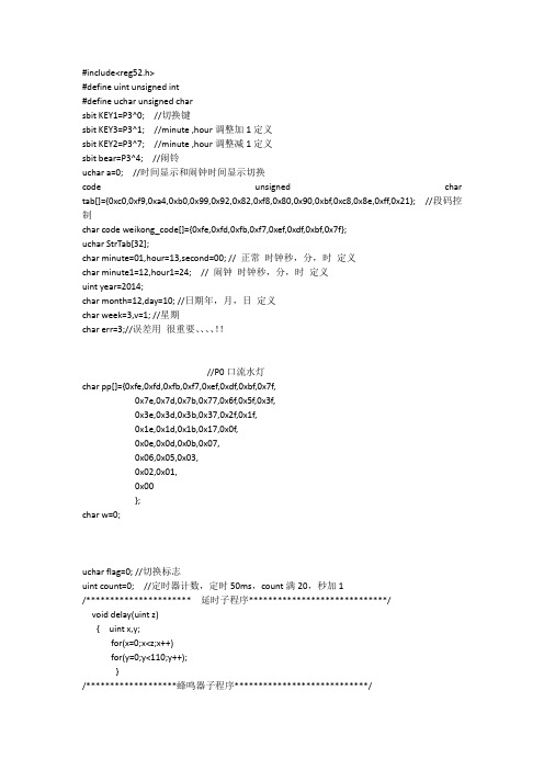
基于51单片机,电子显示时钟带闹钟、整点报时、日期、星期
{ StrTab[1]=second/10; //秒十位
StrTab[0]=second%10; //秒个位
StrTab[2]=10; //间隔符-
StrTab[4]=minute/10; //分十位
StrTab[3]=minute%10; //分个位
StrTab[5]=10; //间隔符-
void display(uchar w[32])
{ unsigned int i,j,c=0;
if(a==0)//正常时间显示
{ for(i=0;i<8;i++) //依次将数组w中八个数取出,并显示
{ P2=weikong_code[i]; //位选
j=w[i]; //取出要显示的数码
P0=tab[j]; //取出段选编码
if(month==13)
{month=1; year++;
if(year==10000)
year=0;}}
week++;//星期走
if(week==8)
week=1;
data1();
week1();
while(second==err);
}
}
/**********************键盘扫描子程序*************************/
{if(dБайду номын сангаасy==30); //闰年29天
{day=1; month++;
if(month==13)
{month=1; year++;
if(year==10000)
year=0;}}}
基于8051和Proteus的数字时钟 程序的编写和仿真
//显 示 函 数
weilock=1; P0=~(1<<2); weilock=0; dualock=1;
P0=(bb==2)?duacode[mint%10]|0x80:duacode[mint%10]; dualock=0; delay(); weilock=1; P0=~(1<<3); weilock=0; dualock=1; P0=(bb==2)?duacode[mint/10]|0x80:duacode[mint/10]; dualock=0; delay();
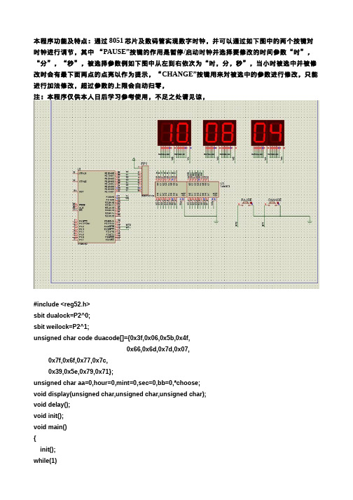
本程序功能及特点:通过 8051 芯片及数码管实现数字时钟,并可以通过如下图中的两个按键对 时钟进行调节,其中 “PAUSE”按键的作用是暂停/启动时钟并选择要修改的时间参数“时”,
“分”,“秒”,被选择参数例如下图中从左到右依次为“时,分,秒”,当小时被选中并被修
改 时 会 有 最 下 面 两 点 的 点 亮 以 作 为 提 示 , “ CHANGE”按 键 用 来 对 被 选 中 的 参 数 进 行 修 改 , 只 能
进行加法修改,超过参数的上限会自动归零, 注:本程序仅供本人日后学习参考使用,不足之处请见谅,
#include <reg52.h> sbit dualock=P2^0; sbit weilock=P2^1; unsigned char code duacode[]={0x3f,0x06,0x5b,0x4f,
0x66,0x6d,0x7d,0x07, 0x7f,0x6f,0x77,0x7c, 0x39,0x5e,0x79,0x71}; unsigned char aa=0,hour=0,mint=0,sec=0,bb=0,*choose; void display(unsigned char,unsigned char,unsigned char); void delay(); void init(); void main() { init(); while(1)
单片机课程设计实验报告 基于单片机的数字时钟 含完整实验代码..
单片机课程设计报告基于单片机的数字时钟姓名:班级:学号:一、前言利用实验板上的4个LED数码管,设计带有闹铃、秒表功能的数字时钟。
功能要求:a)计时并显示(LED)。
由于实验板上只有4位数码管,可设计成显示“时分”和显示“分秒”并可切换。
b)时间调整功能。
利用4个独立按钮,实现时钟调整功能。
这4个按钮的功能为工作模式切换按钮(MODE),数字加(INC),数字减(DEC)和数字移位(SHITF)。
c)定闹功能。
利用4个独立按钮设定闹钟时间,时间到以蜂鸣器响、继电器动作作为闹铃。
d)秒表功能。
最小时间单位0.01秒。
二、硬件原理分析1.电源部分电源部份采用两种输入接口(如上图)。
a)外电源供电,采用2.1电源座,可接入电源DC5V,经单向保护D1接入开关S1。
b)USB供电,USB供电口输入电源也经D1单向保护,送到开关S1。
注:两路电源输入是并连的,因此只选择一路就可以了,以免出问题。
S1为板子工作电源开关,按下后接通电源,提供VCC给板子各功能电路。
电路采用两个滤波电容,给板子一个更加稳定的工作电源。
LED为电源的指示灯,通电后LED灯亮。
2.蜂鸣器蜂鸣器分为有源和无源两种,有源即两引脚有一个直流电源就可以长鸣,无源则需要一个1K左右的脉冲才可以蜂鸣,因此对于按键的提示音及报警蜂鸣使用有源来得方便。
有源也可以当无源使用,而无源则不能当有源使用,当然用有源蜂鸣器作音乐发声会失真厉害。
如上图:单片机P15输出高低电平经R21连接三极管B极,控制三极管的导通与截止,从而控制蜂鸣器的工作。
低电平时三极管导通,蜂鸣器得电蜂鸣,高电平时三极管截止,蜂鸣器失电关闭蜂鸣。
电路使用一个四位共阳型数码管,四个公共阳级由三极管放大电流来驱动,三极管由P10-P13控制开与关。
数码管的阴级由P0口经过电阻限流连接。
例如,要十位的数码管工作,P12输出0,使三极管Q12导通,8脚得电,当P0口相应位有输出0时,点亮相应的LED灯组合各种字符数字。
c8051f020单片机数字时钟
/*本程序只是为了应付课程设计而用据我所知其中至少含有3处bug使用环境c8051f020使用通过*/#include <c8051f020.h>#include <intrins.h>//*****软件仿真I2C总线与HD7279A连接的两根并行口线*****//sbit HD7279_DAT=P1^7;sbit HD7279_CLK=P1^6;//*****宏定义,HD7279A片选信号、数据信号和时钟信号定义*****//#define NOSELECT7279 P5 |= 0x80 //P5^7接片选信号,选种#define SELECT7279 P5 &= ~(0x80) //未选种#define Set7279DAT HD7279_DA T=1 //数据线置1#define Clr7279DAT HD7279_DA T=0 //数据线置0#define Set7279CLK HD7279_CLK=1 //时钟高电平#define Clr7279CLK HD7279_CLK=0 //时钟底电平unsigned char Count1ms;unsigned char xdata NowTime[3]; //当前时间,用于当前时间的设置unsigned char xdata HourH,HourL,MinuteH,MinuteL,SecondH,SecondL;unsigned char xdata mHourH,mHourL,mMinuteH,mMinuteL,mSecondH,mSecondL; unsigned char xdata setHourH,setHourL,setMinuteH,setMinuteL,setSecondH,setSecondL; //*****对所调用其它文件中函数的声明*****//void Delay1ms(unsigned char T); //延时T毫秒void Delay1s(unsigned char T); //延时T秒void Delay1us(unsigned char T); //延时T微秒//*****仿真I2C总线时序发送一字节*****//void SYSCLK_Init (void){int i;OSCXCN = 0x67; //外部晶振22.1184MHzfor (i=0; i < 256; i++) ;while (!(OSCXCN & 0x80)) ; //等待外部晶振稳定OSCICN = 0x88; //选择外部晶振作系统时钟源,允许时钟丢失检测}//*****端口初始化*****//void PORT_Init (void){XBR0 = 0x07; //允许SMBus、SPI0和UART0XBR1 = 0x00;XBR2 = 0x44; //使能交叉开关和弱上拉}//*****定时器T0初始化*****//void Timer0_Init (void){CKCON|=0x8; //T0按系统时钟频率计数TMOD|=0x1; //T0方式1Count1ms=10;TR0 = 0; //停止T0TH0 = (-SYSCLK/1000) >> 8; //定时1ms的时间常数TL0 = -SYSCLK/1000;TR0 = 1; //启动T0IE|= 0x2; //开T0中断}//*****定时器T0中断服务程序(每隔1ms中断1次)*****// void Timer0_ISR (void) interrupt 1{TH0 = (-SYSCLK/1000) >> 8; //重新装入初值TL0 = -SYSCLK/1000;if (Count1ms) Count1ms--; //定时时间减1}//******延时Tμs(软件实现)******//void Delay1us(unsigned char T){while (T){_nop_(); _nop_(); _nop_(); _nop_(); _nop_();--T;}}//******延时Tms(定时器T0实现)******//void Delay1ms(unsigned char T){Count1ms=T;while (Count1ms); //在T0中断服务程序中减1}//*****延时Ts(定时器T0实现)******//void Delay1s(unsigned char T){while (T){Delay1ms(200);Delay1ms(200);Delay1ms(200);Delay1ms(200);Delay1ms(200);T--;}}void Send7279Byte(unsigned char ch){char i;SELECT7279; //置CS低电平Delay1us(50); //延时50μfor (i=0;i<8;i++){if (ch&0x80) //输出1位到HD7279A的DAT A端Set7279DAT;elseClr7279DAT;Set7279CLK;ch=ch<<1; //待发数据左移Delay1us(8);Clr7279CLK;Delay1us(8);}Clr7279DAT; //发送完毕,DATA端置低,返回}//*****仿真I2C总线时序接收一字节*****//unsigned char Receive7279Byte(void){unsigned char i,ch=0;Set7279DAT; //DATA端置为高电平(输入状态)Delay1us(50);for (i=0;i<8;i++){Set7279CLK;Delay1us(8);ch=ch<<1; //接收数据左移1位if (HD7279_DAT) ch+=1; //接收1位数据Clr7279CLK;Delay1us(8);}Clr7279DAT; //接收完毕,DATA端重新置成低电平(输出状态) return ch;}//*****让第No(0到5)位LED闪烁*****//void FlashLED(unsigned char No){unsigned char i;i=0x01;while (No) //将1移到第No位{i=i<<1;No--;}Send7279Byte(~i); //0闪烁、1不闪烁NOSELECT7279;}//******HD7279A左移命令*****//void MoveLeft(void){Send7279Byte(0xA1); //发左移指令NOSELECT7279;}//******采用不译码方式显示时数字0到F的段码******//unsigned char code BdSeg[]={0x7e,0x30,0x6d,0x79, // 0 1 2 30x33,0x5b,0x5f,0x70, // 4 5 6 70x7f,0x7b,0x77,0x1f, // 8 9 a b0x4e,0x3d,0x4f,0x47, // c d e f0x00,0x01};//*显示指针DispBuf所指6个单元数据,点亮第ShowDot(1到6)个LED的小数点*// void DispLED(unsigned char *DispBuf,unsigned char ShowDot){char i,ch;ShowDot--;for (i=0;i<6;i++){ch=DispBuf[i]; //取一字符if ((ch>='a') && (ch<='f')) //转换成数字{ch-='a';ch+=0xa;}if ((ch>='A') && (ch<='F')){ch-='A';ch+=0xa;}Send7279Byte(0x90+5-i); //用不译码方式显示在第i位if (ch==' ') //发送不译码方式显示命令的第2字节Send7279Byte(0x00);elseif (ch=='-')else{if (ShowDot==i) //查表显示,同时点亮小数点Send7279Byte(0x80|BdSeg[ch&0x0f]);elseSend7279Byte(BdSeg[ch&0x0f]);}}NOSELECT7279; //置CS高电平}//*****读取按键值*****//unsigned char GetKeyValue(void){unsigned char KeyValue;if(CPT1CN&0x40) return -1;//if (P17==1) return -1; //无键按下Send7279Byte(0x15); //发读键盘命令KeyValue=Receive7279Byte();NOSELECT7279;return KeyValue;}//***等待按键释放,用C8051F020的比较器硬件检测,也可以用软件延时实现***//void WaitKeyOff(void){while (!(CPT1CN&0x40));}//*****显示任意长整型数据*****//void DispValue(unsigned long xx){unsigned char buf[6];buf[0]=(xx%1000000)/100000; //最高位buf[1]=(xx%100000)/10000;buf[2]=(xx%10000)/1000;buf[3]=(xx%1000)/100;buf[4]=(xx%100)/10;buf[5]=(xx%10); //最低位DispLED(buf,0); //调用显示函数,所有小数点都不点亮}//**从键盘读取6位数据,用于存储时间,格式是HHMMSS,所读数据转换成长整型**// unsigned long InputNum(void){unsigned long Num=0;unsigned char i=0, KeyValue;DispLED(" -",0);//输入提示FlashLED(0); //第一位闪烁Delay1s(1);while(1){KeyValue=GetKeyValue();if (i==6) //6位数据输入完,返回{FlashLED(8);//关闪烁return Num;}if((KeyValue>=0) && (KeyValue<=9)) //只接收十进制的0到9{i++;Send7279Byte(0xC8); //发送键码值,按方式1译码下载显示Send7279Byte(KeyValue);MoveLeft(); //显示并左移一位,仍使低位显示并闪烁。
基于51单片机的电子数字钟设计的外文翻译
基于51单片机的电子数字钟设计的外文翻译AT89C51 Family Users Guide1 FeaturesCompatible with MCS-51 Products4K Bytes of In-System Reprogrammable Flash Memory– Endurance 1000 WriteErase CyclesFully Static Operation 0 Hz to 24 MHzThree-level Program Memory Lock128 x 8-bit Internal RAM32 Programmable IO LinesTwo 16-bit TimerCountersSix Interrupt SourcesProgrammable Serial ChannelLow-power Idle and Power-down Modes2 DescriptionThe AT89C51 is a low-power high-performance CMOS 8-bit microcomputer with 4K bytes of Flash programmable and erasable read only memory PEROM The device is manufactured using Atmels high-density nonvolatile memory technology and is compatible with the industry-standard MCS-51instruction set and pin-out The on-chip Flash allows the program memoryto be reprogrammed in-system or by a conventional nonvolatile memory programmer By combining a versatile 8-bit CPU with Flash on a monolithic chip the Atmel AT89C51 is a powerful microcomputer which provides ahighly-flexible and cost-effective solution to many embedded control applications3 Pin Configurations4 Lock DiagramThe AT89C51 provides the following standard features 4K bytes of Flash 128 bytes of RAM 32 IO lines two 16-bit timercounters a five vectortwo-level interrupt architecture a full duplex serial port on-chip oscillator and clock circuitry In addition the AT89C51 is designed withstatic logic for operation down to zero frequency and supports two software selectable power saving modes The Idle Mode s tops the CPU while allowing the RAM timercounters serial port and interrupt system to continue functioning The Power-down Mode saves the RAM contents butfreezes the oscillator disabling all other chip functions until the next hardware reset5 Pin DescriptionVCC Supply voltageGND GroundPort 0Port 0 is an 8-bit open-drain bi-directional IO port As an output port each pin can sink eight TTL inputs When 1s are written to port 0 pins the pins can be used as high-impedance inputsPort 0 may also be configured to be the multiplexed low-order addressdata bus during accesses to external program and data memory Inthis mode P0 has internal pull-upsPort 0 also receives the code bytes during Flash programming andoutputs the code bytes during program verification External pull-ups are required during program verificationPort 1Port 1 is an 8-bit bi-directional IO port with internal pull-ups The Port 1 output buffers can sinksource four TTL inputs When 1s are writtento Port 1 pins they are pulled high by the internal pull-ups and can beused as inputs As inputs Port 1 pins that are externally being pulled low will source current IIL because of the internal pull-ups Port 1 alsoreceives the low-order address bytes during Flash programming and verificationPort 2Port 2 is an 8-bit bi-directional IO port with internal pull-ups The Port 2 output buffers can sinksource four TTL inputs When 1s are writtento Port 2 pins they are pulled high by the internal pull-ups and can beused as inputs As inputs Port 2 pins that are externally being pulled low will source current IIL because of the internal pull-ups Port 2 emitsthe high-order address byte during fetches from external program memoryand during accesses to external data memory that uses 16-bit addressesMOVX DPTR In this application it uses strong internal pull-ups whenemitting 1s During accesses to external data memory that uses 8-bitaddresses MOVX RI Port 2 emits the contents of the P2 Special Function Register Port 2 also receives the high-order address bits and some c ontrolsignals during Flash programming and verificationPort 3Port 3 is an 8-bit bi-directional IO port with internal pull-ups The Port 3 output buffers can sinksource four TTL inputs When 1s are writtento Port 3 pins they are pulled high by the internal pull-ups and can beused as inputs As inputs Port 3 pins that are externally being pulled low will source current IIL because of the pull-ups Port 3 also serves the functions of various special features of the AT89C51 as listed belowPort Pin Alternate Functions P30 RXD serial input portP31 TXD serial output port P32 INT0 external interrupt 0P33 INT1 external interrupt 1 P34 T0 timer 0 external inputP35 T1 timer 1 external input P36 WR external data memory write strobe P37 R D external data memory read strobe Port 3 also receives some c ontrol signals for Flash programming and verification RSTReset input A high on this pin for two machine cycles while theoscillator is running resets the deviceALEAddress Latch Enable output pulse for latching the low byte of theaddress during accesses to external memory This pin is also the programpulse input PROG during Flash programming In normal operation ALE isemitted at a constant rate of 16 the oscillator frequency and may be usedfor external timing or clocking purposes Note however that one ALE pulse is skipped during each access to external Data Memory If desired ALEoperation can be disabled by setting bit 0 of SFR location 8EH With thebit set ALE is active only during a MOVX or MOVC instruction Otherwisethe pin is weakly pulled high Setting the ALE-disable bit has no effectif the microcontroller is in external execution modeProgram Store Enable is the read strobe to external program memoryWhen the AT89C51 is executing code from external program memory isactivated twice each machine cycle except that two activations areskipped during each access to external data memoryVPPExternal Access Enable must be strapped to GND in order to enablethe device to fetch code from external program memory l ocations startingat 0000H up to FFFFH Note however that if lock bit 1 is programmed willbe internally latched on reset should be strapped to VC C for internalprogram executions This pin also receives the 12-volt programming enable voltage VPP during Flash programming for parts that require 12-volt VPP XTAL1Input to the inverting oscillator amplifier and input to the internal clock operating circuitXTAL2Output from the inverting oscillator amplifier6 Oscillator CharacteristicsXTAL1 a nd XTAL2 a re the input and output respectively of an inverting amplifier which can be configured for use as an on-chip oscillator as shown in Figure 1 Either a quartz crystal or ceramic resonator may be used Todrive the device from an external clock source XTAL2 should be leftunconnected while XTAL1 is driven as shown in Figure 2 There are no requirements on the duty cycle of the external clock signal since the input to the internal clocking circuitry is through a divide-by-two flip-flopbut minimum and imum voltage high and low time specifications must beobservedOscillator ConnectionsNote C1 C2 30 pF±10 pF for Crystals40 pF±10 pF for Ceramic ResonatorsExternal Clock Drive Configuration7 Idle ModeIn idle mode the CPU puts itself to sleep while all the on-chipperipherals remain active The mode i s invoked by software The content of the on-chip RAM and all the special functions registers remain unchanged during this mode T he idle mode c an be terminated by any enabled interruptor by a hardware reset It should be noted that when idle is terminatedby a hard ware reset the device normally resumes program execution fromwhere it left off up to two machine cycles before the internal resetalgorithm takes control On-chip hardware inhibits access to internal RAM in this event but access to the port pins is not inhibited To eliminatethe possibility of an unexpected write to a port pin when Idle is terminated by reset the instruction following the one that invokes Idleshould not be one that writes to a port pin or to external memory8 Power-down ModeIn the power-down mode t he oscillator is stopped and the instruction that invokes power-down is the last instruction executed The on-chip RAM and Special Function Registers retain their values until the power-downmode i s terminated The only exit from power-down is a hardware reset Reset redefines the SFRs but does not change the on-chip RAM The reset shouldnot be activated before VCC is restored to its normal operating level and must be held active long enough to allow the oscillator to restart andstabilize9 Programming the FlashThe AT89C51 is normally shipped with the on-chip Flash memory arrayin the erased state that is contents FFH and ready to be programmedThe programming interface accepts either a high-voltage 12-volt or alow-voltage VCC program enable signal The low-voltage programming mode provides a convenient way to program the AT89C51 inside the users system while the high-voltage programming mode is compatible with conventionalthird party Flash or EPROM programmers The AT89C51 is shipped with either the high-voltage or low-voltage programming mode enabled The respectivetop-side marking and device signature codes are listed in the followingtableThe AT89C51 code memory array is programmed byte-by-byte in either programming mode T o program any nonblank byte in the on-chip Flash Memory the entire memory must be erased using the Chip Erase Mode10 Flash Programming and Verification CharacteristicsTA 0°C to 70°C VCC 50±10Note 1 Only used in 12-volt programming mode11 DC CharacteristicsTA -40°C to 85°C VCC 50V±20 unless otherwise notedNotes1 under steady state non-transient conditions IOL must be externally limited as followsimum IOL per port pin 10 mAimum IOL per 8-bit port Port 0 26 mAPorts 1 2 3 15 mAimum total IOL for all output pins 71 mAIf IOL exceeds the test condition VOL may exceed the related specification Pins are not guaranteed to sink current greater than thelisted test conditions。
基于8051单片机的数字钟[附图+源码+中英文文献]
用单片机做一个数字钟是单片机应用中的一个典型例子.本设计充分利用8051单片机的4个I/O口,外加两片74LS07作数码管驱动电路,12位数码管的片选信号由74LS138译码器提供,采用动态显示。为增加驱动能力,又在数码管的阴极端加9013驱动管。
我们设计出的电子钟采用24小时制计时,其中添加了整点报时,半点报时和闹铃提示功能。另外为了需要,我们还添加了秒表功能。
/PSEN:外部程序存储器的选通信号。在由外部程序存储器取指期间,每个机器周期两次/PSEN有效。但在访问外部数据存储器时,这两次有效的/PSEN信号将不出现。
/EA/VPP:当/EA保持低电平时,则在此期间外部程序存储器(0000H-FFFFH),不管是否有内部程序存储器。注意加密方式1时,/EA将内部锁定为RESET;当/EA端保持高电平时,此间内部程序存储器。在FLASH编程期间,此引脚也用于施加12V编程电源(VPP)。
ALE/PROG:当访问外部存储器时,地址锁存允许的输出电平用于锁存地址的地位字节。在FLASH编程期间,此引脚用于输入编程脉冲。在平时,ALE端以不变的频率周期输出正脉冲信号,此频率为振荡器频率的1/6。因此它可用作对外部输出的脉冲或用于定时目的。然而要注意的是:每当用作外部数据存储器时,将跳过一个ALE脉冲。如想禁止ALE的输出可在SFR8EH地址上置0。此时, ALE只有在执行MOVX,MOVC指令是ALE才起作用。另外,该引脚被略微拉高。如果微处理器在外部执行状态ALE禁止,置位无效。
⑵ 对于74LS系列,CD4000系列以及一些大规模集成电路芯片(如8155,8253,8259等),都可以和MCS-51系列单片机直接接口。具体使用时,可以查阅有关器件手册或参考典型电路
⑶ 对一些线性组件,特别是应用键盘、码盘、LED显示器等输入/输出设备时,应当尽量增加驱动部分的容量,否则,单片机将提供不出足够的驱动电流供给负载使用
- 1、下载文档前请自行甄别文档内容的完整性,平台不提供额外的编辑、内容补充、找答案等附加服务。
- 2、"仅部分预览"的文档,不可在线预览部分如存在完整性等问题,可反馈申请退款(可完整预览的文档不适用该条件!)。
- 3、如文档侵犯您的权益,请联系客服反馈,我们会尽快为您处理(人工客服工作时间:9:00-18:30)。
/EA/VPP:当/EA保持低电平时,则在此期间外部程序存储器(0000H-FFFFH),不管是否有内部程序存储器。注意加密方式1时,/EA将内部锁定为RESET;当/EA端保持高电平时,此间内部程序存储器。在FLASH编程期间,此引脚也用于施加12V编程电源(VPP)。
关键词:单片机最小系统 动态显示 译码器电子钟
ABSTRACT
It is a typical example to make a digital clock with the MCU. This design makes a good use of the I/Oredirections,And we use two pieces of 74ls07 as the drivers for the LED, two pieces of 74ls138 as theencoders. We desplay the time indynamicmathod. For thepurposeof improving the ability of driving ,we add the 9013 as the driver for the LED.
出于实验室条件和经济条件的影响,作者没有在数字钟上加上过多的功能,不过也实现了数字时钟的基本功能,如计时功能、整点报时功能,闹铃功能,调时功能和秒表功能等
第一章单片机制作数字钟的原理
以8051为主芯片制作多功能数字钟的方案中,时钟信号主要由8051单片机的定时器/计数器来提供,对时间进行设置和进行闹铃设置主要用到单片机的外部中断。外部控制电路及显示电路都用到了他的I/O口,在本章我们主要介绍一下关于8051单片机定时器/计数器、中断源及中断系统以及8051的I/O口的特性及应用
1.1 主芯片8051的硬件资源
1.1.1单片机的概念
单片机(microcontroller,又称微控制器)是在一块硅片上集成了各种部件的微型计算机。这些部件包括中央处理器CPU、数据存储器RAM、程序存储器ROM、定时器/计数器和多种I/O接口电路。图1-1是8051单片机的基本结构图
8051单片机的结构特点有以下几点:
P3口:P3口管脚是8个带内部上拉电阻的双向I/O口,可接收输出4个TTL门电流。当P3口写入“1”后,它们被内部上拉为高电平,并用作输入。作为输入,由于外部下拉为低电平,P3口将输出电流(ILL)这是由于上拉的缘故。
P3口也可作为AT89C51的一些特殊功能口,如下表所示:
P3.0 RXD(串行输入口)
1.1.2 8051的芯片引脚
如图1-2所示
VCC:供电电压。
GND:接地。
P0口:P0口为一个8位漏极开路双向I/O口,每脚可吸收8TTL门电流。当P1口的管脚第一次写1时,被定义为高阻输入。P0能够用于外部程序数据存储器,它可以被定义为数据/地址的第八位。在FIASH编程时,P0 口作为原码输入口,当FIASH进行校验时,P0输出原码,此时P0外部必须被拉高。
单片微型计算机简称单片机,又成为控制器。他是在一块半导体上,集成了CPU、ROM、RAM、I/O接口、定时器/计数器、中断系统等功能部件,构成了一台完整的数字计算机。单片机在生产生活中的许多方面得到广泛的应用,例如,生活中五彩变幻的霓虹灯,手机通信,温度检测,流量控制等都涉及到单片机。
单片机的应用结束了计算机专业人员“垄断”计算机系统开发与应用的时代,他既给各种专业人员、特别是许多工程技术人员带来了学习和掌握计算机技术的紧迫性,同时也带来了可能性,因为组成计算机应用系统变得容易、“平凡”,增强了人们进入这一领域的信心
The work we design use 24 hour format, we add a alarm, so the clock can remind us at the time we set ahead. Moreover for the sake of demand, we still add the stop-watch function.
XTAL1:反向振荡放大器的输入及内部时钟工作电路的输入。
XTAL2:来自反向振荡器的输出。
1.1.3 使用I/O口的注意事项
⑴ P1,P2,P3口的输出缓冲器可驱动4个LSTTL电路。对于HCMOS芯片单片机的I/O口,在正常情况下,可任意由TTL或NMOS电路驱动。HMOS及CMOS性的单片机I/O口有集电极开路或漏极开路的输出来驱动时,不必外加上拉电阻
二、单片机的特点
单片机的集成度很高,他将微型计算机的主要部件都集成在一块芯片上,具有下列特点:
1.体积小、重量轻、价格便宜、耗电少;
2.根据工程环境要求设计,且许多功能部件集成在芯片内部,其信号通道受外界影响小,故可靠性高,抗干扰性能优于采用一般的CPU
3.控制功能强,运行速度快。其结构组成与指令系统都着重满足工控要求,又极丰富的条件分支指令,有很强的位处理功能和I/O口逻辑操作功能。
摘要
用单片机做一个数字钟是单片机应用中的一个典型例子.本设计充分利用8051单片机的4个I/O口,外加两片74LS07作数码管驱动电路,12位数码管的片选信号由74LS138译码器提供,采用动态显示。为增加驱动能力,又在数码管的阴极端加9013驱动管。
我们设计出的电子钟采用24小时制计时,其中添加了整点报时,半点报时和闹铃提示功能。另外为了需要,我们还添加了秒表功能。
8051的中断系统允许接受五个独立的中断源,即两个外部中断申请,两个定时器/计数器中断以及一个串行口中断。
外部中断申请通过INTO和INT1(即P3.2和P3.3)输入,输入方式可以使电平触发(低电平有效),也可以使边沿触发(下降沿有效)。两个定时器中断请求是当定时器溢出时向CPU提出的,即当定时器由状态1转为全零时提出的。第五个中断请求是由串行口发出的请求
P1口:P1口是一个内部提供上拉电阻的8位双向I/O口,P1口缓冲器能接收输出4TTL门电流。P1口管脚写入1后,被内部上拉为高,可用作输入,P1口被外部下拉为低电平时,将输出电流,这是由于内部上拉的缘故。在FLASH编程和校验时,P1口作为第八位地址接收。
P2口:P2口为一个内部上拉电阻的8位双向I/O口,P2口缓冲器可接收,输出4个TTL门电流,当P2口被写“1”时,其管脚被内部上拉电阻拉高,且作为输入。并因此作为输入时,P2口的管脚被外部拉低,将输出电流。这是由于内部上拉的缘故。P2口当用于外部程序存储器或16位地址外部数据存储器进行存取时,P2口输出地址的高八位。在给出地址“1”时,它利用内部上拉优势,当对外部八位地址数据存储器进行读写时,P2口输出其特殊功能寄存器的内容。P2口在FLASH编程和校验时接收高八位地址信号和控制信号。
第三阶段 1982~1983年,高级8位机阶段,发展了高性能的8位单片机,例如MCS-51系列单片机,它带有串行I/O接口和多个16位定时器/计数器,具有多级中断功能。这一阶段进一步拓宽了单片机的应用范围,使之能用于智能终端、局部网络接口,并挤入了个人计算机领域。
第四阶段 1983年以后,16位单片机阶段。发展了MCS-96系列等16位单片机。功能很强,价格却迅速下降。片内有A/D转换器;可快速输入、输出;可用于电机控制;网络通信能力有显著提高。
单片机的历史非常短暂,然而发展十分迅猛。自1971年美国Intel公司首先研制出4位单片机4004以来,他的发展可粗略划分为四个阶段:
第一阶段1971~1976年,属萌芽阶段。发展了各种4位单片机,多用于家用电器、计算器、高级玩具。
第二阶段 1976~1980年,为初级8位机阶段,发展了各种中、低档8位单片机,典型的如MCS-48系列单片机,片内含多个8位并行I/O接口、一个8位定时器/计数器,不带串行接口,其功能可以满足一般工业控制和智能化仪器仪表等的需要。
●8位CPU;
●片内振荡器及时钟电路;
●32根I/O线;
●外部存储器ROM和RAM,寻址范围各64KB;
●两个16位的定时器/计数器;
●5个中断源,2个中断优先级
●全双工串行口
●布尔处理器
2.定时器/计数器
8051内部有两个16位可编程定时器/计数器,记为T0和T1。16位是指他们都是由16个触发器构成,故最大计数模值为2 -1。可编程是指他们的工作方式由指令来设定,或者当计数器来用,或者当定时起来用,并且计数(定时)的范围也可以由指令来设置。这种控制功能是通过定时器方式控制寄存器TMOD来完成的
Key words:theMinimum systemdrivedynamicdisplay encoder
引言
当今,计算机技术带来了科研和生产的许多重大飞跃,微型计算机的应用已渗透到生产、生活的各个方面。其中单片微型计算机虽然问世不久,然而体积小、价廉、功能强,其销售额以每年近80%的速率增长。他的性能不断提高,适用范围愈来愈宽,在计算机应用领域已占有日益重要的地位。
如果需要,定时器在计到规定的定时值是可以向CPU发出中断申请,从而完成某种定式的控制功能。在计数状态下同样也可以申请中断。定时器控制寄存器TCON用来负责定时器的启动、停止以及中断管理
在定时工作时,时钟由单片机内部提供,即系统时钟经过12分频后作为定时器的时钟。技术工作时,时钟脉冲由TO和T1输入
3.中断系统
⑵ 对于74LS系列,CD4000系列以及一些大规模集成电路芯片(如8155,8253,8259等),都可以和MCS-51系列单片机直接接口。具体使用时,可以查阅有关器件手册或参考典型电路
⑶ 对一些线性组件,特别是应用键盘、码盘、LED显示器等输入/输出设备时,应当尽量增加驱动部分的容量,否则,单片机将提供不出足够的驱动电流供给负载使用
4.片内存储器的容量不可能很大;引脚也嫌少,I/O引脚常不够用,且兼第二功能,第三功能但存储器和I/O口都易于扩展