Windows 7 官方用户手册(英文版)第五部分
win7使用入门培训操作手册
1、问题步骤记录器您只要单击开始菜单、键入PSR,按住Enter键,再点击开始记录按钮即可。
启用这项功能后,当您的朋友进行问题操作时,该记录器将会逐一记录您的操作步骤,并将它们压缩在一个MHTML 文件中。
这将有助于缩短您的故障排除时间。
2、系统还原在以前的Windows版本中使用系统还原具有很大的不确定性,你根本无法告知系统去还原哪些应用程序。
而Windows 7就不同了,右击电脑,选择属性,系统保护,系统还原,然后选择您想要的还原点,点击“扫描受影响的应用程序”,Windows就会告知您哪些应用程序受到影响,通过选择还原点进行删除或者是修复。
3、桌面幻灯片Windows 7中有许多吸引人的新的墙纸,因此您很难决定是使用哪一张,那么为什么不使用桌面幻灯片功能呢?右击桌面的空白位置,选择个性化,桌面背景,然后在选择喜欢的图片的时候按住Ctrl键,接着再选择您想要的图片的变换周期,选择Shuffle使得图片随机显示,自此,桌面幻灯片的功能就设置完成了。
4、自动排列您的桌面如果您的Windows 7桌面上的图标分散得到处都是,那么您只需右击桌面,选择“查看”——自动排列即可。
还有另外一种简便的方法就是按F5键刷新即可。
快捷键的使用Windows 7比Vista要好用而且有很多新功能。
不过,由于系统较新,其中的一些功能并不是很容易被人们所发现,所以我们把其中的一些最重要的技巧和窍门创建成一个列表并且一步一步的向大家进行介绍。
把当前窗口停靠在屏幕左侧这个新功能看起挺有用,因为有些时候,我们会被屏幕中浮着的近乎疯狂的窗口们所困扰,并且很难把他们都弄到一边。
现在我们使用键盘的快捷键就可以很轻松的做到了。
按WIN+左键把它靠到屏幕的左边去吧。
把当前窗口停靠在屏幕右侧按WIN+右键可以把窗口靠到右侧显示或隐藏浏览预览面板按 ALT+P 隐藏或者显示浏览的预览窗口锁定屏幕Windows 7的开始菜单里不再有锁定按钮,所以现在用户要按WIN+L去锁定它。
Windows 7 官方用户手册(英文版)第二部分
Windows PowerShell 2.0™
Automate repetitive tasks with this graphical scripting editor that helps you write scripts that access underlying technologies.
20
21
Top Features for IT Professionals
From networking to security and search to user management, Windows 7 offers IT professionals a wide range of new and improved features. These include the following:
What;’s New in Windows 7
Application and Device Compatibility
We recognize that your PC experience involves programs and devices from many different providers, so we’ve made a significant effort to ensure that the applications and devices you use and love are compatible with Windows 7 and work the way you’d expect them to. Windows 7 helps address application compatibility in several ways. Perhaps most importantly, we worked to minimize changes in the way applications and devices interact with Windows. As a result, the work done by third-party software and hardware developers to make their products work on Windows Vista generally carries forward for Windows 7. In most cases, the same software and hardware that works with Windows Vista will also work with Windows 7. In addition, we created a comprehensive list of the most widely used consumer and business applications, which were tested throughout the development cycle. We also created new and improved tools such as the Windows Upgrade Advisor, Application Compatibility Toolkit (ACT), Windows Compatibility Center, Quality Cookbook, Application Verifier, and ISV Developer Portal to help customers and software developers assess application compatibility. For untested programs or applications developed in-house, Windows 7 offers a number of in-the-box compatibility aids. For example, if a program fails to install because of a hard-coded version check, the Program Compatibility Troubleshooter can automatically fix the problem (with the user’s consent) and rerun the installer. Windows 7 also includes an expanded application shim infrastructure and a Problem Steps Recorder that people can use to capture application compatibility issues for evaluation by technical experts. Furthermore, we continually monitor application compatibility issues throughout the Windows ecosystem. We designed Windows 7 to monitor application health and, with the user’s permission, provide feedback to Microsoft so that we can work quickly with application developers to resolve compatibility problems and issue a fix if necessary. Microsoft has also invested in partner outreach efforts so that software developers have the resources required to ensure application compatibility. As with applications, we are also working to ensure that devices compatible with Windows Vista will work just as well with Windows 7. As a part of this effort, we have greatly expanded the list of devices and peripherals being tracked for compatibility with Windows 7. We have identified thousands of devices through data collected via the Customer Experience Improvement Program and through outreach efforts to device and PC manufacturers, and we have tested those devices for compatibility with Windows 7. When updated device drivers are required, we are working to ensure that you can get them directly from Windows Update or through links to driver downloads on device manufacturer Web sites.
Fadal用户手册-第五部分:子程序与子例程说明书

Section 5: Subroutines & Subprograms Subroutines Subroutines are used for contours, hole patterns, or any actions that repeat orare used in many locations. Typically subroutines will contain only positionalmoves. Feed rates, tool changes, spindle speeds, rotation, and other codes arereserved for the main program. However, most codes can be in a subroutine.All user defined subroutines must be at the beginning of the program beforethe main section of the program. Only the O word and comments may be usedprior to the first subroutine. Subroutines cannot be defined in asubprogram. However, if the START macro command is used, subroutines canbe defined in subprograms (see Section Eighteen, Macros).The format of the L word for a subroutine definition is LNNKK.Beginning aSubroutineNN is the subroutine number (01-89).KK will always be 00 (zero, zero).EXAMPLE:L0100 (or L100) This would define the beginning of subroutine number 1L2300 This would define the beginning of subroutine number 23The maximum number allowed for NN is 89. Subprograms 90 - 99 are used bythe control for Fixed subroutines (see Section Six, Fixed Subroutines). The linewith the L word that defines the subroutine can only have a parenthesis or anasterisk for a comment. No other codes are permitted.Calling a Subroutine The format for the subroutine call is LNNKK. NN is the subroutine number (01-99). KK is the number of repetitions (01-99).EXAMPLE:L101 This would call, or use, subroutine number 1, one timeL2315 This would call, or use, subroutine number 23, fifteen timesThe LNNKK word must be the only word in the block in which it appears withthe exception of R parameter definitions, G66, and a parenthesis or an asteriskfor a comment. After a subroutine has been executed, it will return to the linewhere it was called and the program will continue from that line.Ending a Subroutine A subroutine ends with the L word that starts the next subroutine or with anM17. The M17 must be the only word in the block in which it appears.The last subroutine in the program MUST have an M17 coded at the end. Main Program An M30 marks the end of the subroutine section and the start of the mainprogram. An M17 marks the end of the last subprogram, which must be on aline before an M30. The M30 must be the only word in the block in which itappears.When the operator presses the auto button the control will process theprogram. The control will recognize the existence of subroutines by the L #00 atthe beginning of the program. The control will then recognize the beginning ofthe main program by the M30 code. When the control is ready to run, the linejust after the M30 will be the first line to appear on the screen of the pendent.When the M30 is used to end the subroutine section, an M2 is used to end theprogram. At the end of the program, the M2 will cause the program to beginagain at the line after the M30 code.EXAMPLE:N10 M17 This marks the end a subN11 M30N12 G0 G90 S2000 M3 E1 X0 Y0 End of subroutine sectionN13 H1 M7 Z.1 Beginning of the Main programN14 L201 Sub #2 one time. When sub #2 is complete it will return hereN15 M5 M9 G80Nesting A subroutine may be called for execution from another subroutine. This iscalled subroutine “nesting.”Subroutines may be nested as many as seven deep. This means that at somepoint in a subroutine another subroutine can be called, and then from thatsubroutine another can be called and so forth up to seven times.Subroutines cannot be defined in a subprogram. However if the STARTmarco command is used, subroutines can be defined in subprograms (seeSection Eighteen, Macros).EXAMPLE:N1 O1234 (SUBROUTINE EXAMPLE PROGRAMN2 L100 This marks the beginning of sub #1N3 X.5 Y.5N4 X-.5N5 G80N6 M17 This marks the end a subN7 L200 This marks the beginning of sub #2N8 G81 G99 R0+.1 Z-.1 F35.N9 L101 Sub#1 is being called from sub #2. Sub #1 is nested inside sub#2N10 M17 This marks the end a subroutineN11 M30 End of subroutine sectionN12 G0 G90 S2000 M3 E1 X0 Y0 Beginning of the Main programN13 H1 M7 Z.1N14 L201 Sub #2 one time. When sub #2 is complete it will return hereN15 M5 M9 G80N16 G0 G49 G90 Z0N17 M2 End of the Main program. In the auto mode the program will rerunfrom line N12EXAMPLE:Drill and Tap 2 holes using subroutine to define positions.N1 O1 (SAMPLE PROGRAMN2 L100 Define Subroutine 1N3 X.5 Y.5N4 X-.5N5 G80N6 M17 End SubroutineN7 M30 End of Subroutine definitionN8 M6 T1N9 Tool #1 drillN10 G0 G90 S3500 M3 E1 X0 Y0N11 H1 M7 Z.25 Start main programDrill cycleN12 G81 G99 R0+.1 Z-.475 F20.N13 L101 Call Subroutine 1N14 N15 M6 T2 Tool #2 tapN16 G0 G90 S600 M3 E1 X0 Y0N17 H2 M7 Z.25N18 G84 G98 R0+.1 Z-.5 F600. Q.05 Tap CycleN19 L101 Call SubroutineN20 M5 M9N21 G0 G49 G90 Z0N22 E0 X0 Y0N23 M6 T1N24 M2•Block N2 uses the L word to identify the beginning of the subroutine.•Block N3 through N4 identify the X and Y locations.•Block N6 uses M17 to define the end of the subroutine.•Block N7 uses M30 to define the end of subroutine definition and the beginning of the main program.Upon execution of the program, the CNC always begins processing from the first block. When the first block contains the L word, the CNC examines each following block, until the M17, M30 codes are encountered. The execution begins with the block following the M30.The example program begins execution from block N8. Block N13 causes program execution from block N2 until the M17 is encountered at block N6. After completing the subroutine call, the program execution is returned to the next block following the subroutine call (N14).Parametric Programming Generalized subroutines can be written with the use of subroutine parameters. In a generalized subroutine, the numerical value of the A, B, E, F, G, H, I, J, K, L, M, P, Q, R, S, T, X, Y, Z words need not be specified directly. Values that are to be determined at the time of the subroutine call are specified indirectly by the use of the parametric reference "R". There are ten parameters, R0 through R9.X+R1 directs the CNC to take the current value of parameter R1 as the value for the X word. X-R1 directs the CNC to take the negative of the current value of parameter R1 as the value for the X word.The values of the parameters are modal. They are modified by programming an R word in a line of code. For example:R0+.137 defines the value of parameter R0 to +.137. This value is used by any R0 in the program until it is redefined.In the example below, subroutine L100 is a generalized subroutine to create a “D” pattern. Block N7 of the example calls the subroutine with the parameters R0 and R1 set to 2.0 and 1.0 respectively.EXAMPLE:N1 L100 (DEFINE SUBROUTINE 1N2 G1 Y+R0 (FIRST LEG OF “D” PATTERNN3 G2 X+R1 Y-R1 J-R1N4 G2 X-R1 Y-R1 I-R1 (BACK TO BEGINNINGN5 M17N6 M30 (END OF SUBROUTINE DEFINITIONN7 L101 R0+2. R1+1. (CALL SUBROUTINE 1, (EXECUTE 1 TIMEAll R values are modal, and are not cleared at the beginning of a program. Thevalues are cleared at power on and are zero until they are defined.Indefinite Subroutine Repetitions In some cases a subroutine needs to be repeated an indefinite number of times. This is accomplished by using a .1 extension at the end of a subroutine call.N1 L100N2 E1 X.45 Y-1.05N3 G81 G99 R0+.1 Z-.75 F80. X.5 Y-1.N4 X2.5N5 G80N6 Z1.N7 E0 X0 Y0N8 G4 P66000 The machine is in the Waiting state, spindle & coolant onN9 M17N10 M30N11 G90 G0 S10000 E1 X.45 Y-1.05N12 H1 Z1. M7N13 L101.1 The .1 extension repeats sub #1 an indefinite number of timesN14 M2Subprograms Subprograms function for the same purpose as a subroutine. They can beused instead of subroutines. For program editing purposes a program thatuses subroutines is easier to edit. The operator can edit both the main andsubroutine section of the program without switching to another program.Editing a subprogram requires that the operator first switch to the subprogram,edit, then switch back to the main program. The main program must becurrently active to execute the program.Subprograms are generally used in Format 2 style programs. A main programis identified by the use of the M30 code at the end, which functions like the M2would in a Format 1 style program. The subprogram is identified by using theM99 code at the end. The M99 functions as the point to either return to thebeginning of the subprogram for a repeat, or to return to the line where thesubprogram was called.Subprograms cannot contain subroutines. However a subprogram can becalled from a subroutine. If START macro command is used, subroutines canbe defined in subprograms (see Section Eighteen, Macros).EXAMPLE:O1 (MAIN PROGRAMG90 G0 G17 G80 G40 G49 Z0M6 T1 (TOOL #1S2000 M3 G54 X0 Y0H1 D1 Z1. M8G82 G99 R0+.1 Z-.25 F45.M98 P2 L1 Call subprogram #2 one time. This is where the sub returns after executionM5 M9G80G90 G0 G49 Z0M6 T2 (TOOL #2G90 G0 S2000 M3 G54 X0 Y0H2 D2 Z1. M8G83 G99 R0+.1 Z-2.1 F37. Q.3143M98 P2 L1 Call subprogram #2 one time. This is where the sub returns to after executionM5 M9G80G0 G90 G49 Z0G59 X0 Y0M30O2 (SUBPROGRAM FOR HOLE LOCATIONSX2. Y1.X3. Y1.M99 End of subprogram and return to main programThis page intentionally left blank.。
WES7 定制手册
Windows Embedded Standard 2011 CTP2 Lab ManualWindows Embedded Standard 2011 – CTP2 Lab ManualTable of Contents1 Preparing to Use Windows Embedded Standard 2011 ...................................................................... 5 1.1 1.2 1.3 1.4 1.5 1.6 Introduction .............................................................................................................................. 5 Related Windows 7 Documentation .......................................................................................... 5 Minimum Device Hardware Requirements ................................................................................ 5 Release Notes ........................................................................................................................... 5 Install Windows Embedded Standard 2011 Toolkit .................................................................... 6 1.5.1 1.6.1 1.6.2 1.7 1.7.1 1.7.2 2 2.1 Open Windows Embedded Standard 2011 Toolkit Help .................................................. 6 Make Your Utility Disk Bootable ..................................................................................... 7 Add Image Builder Wizard to Your Utility Disk ................................................................ 7 Create a Windows PE Utility Disk with Image Configuration Editor ................................. 8 Create a Custom Windows PE Image .............................................................................. 8 Create a Utility Drive ................................................................................................................. 7Create a Windows Preinstallation Environment Utility Drive (Optional) ..................................... 8Build Windows Embedded Standard 2011 Images ............................................................................ 9 Build a Windows Embedded Standard 2011 Image with Image Builder Wizard .......................... 9 2.1.1 2.1.2 2.2 2.2.1 2.2.2 2.2.3 2.2.4 2.2.5 2.2.6 2.2.7 Build a Thin Client Image with Embedded Enabling Features .......................................... 9 Build an Image with Embedded Core Only .................................................................... 11 Build a Thin Client Image with Custom Settings ............................................................ 11 Add Update Packages to a Distribution Share (Optional) .............................................. 14 Add Third-Party Software (Optional) ............................................................................ 15 Run a Custom Script (Optional) .................................................................................... 16 Add Third-Party Drivers (Optional) ............................................................................... 17 Make Your Install Fully Unattended (Optional) ............................................................. 17 Create Image Builder Wizard Disk from Answer File (optional) ..................................... 24Build a Windows Embedded Standard 2011 Image Using Image Configuration Editor ............. 113Deploy an Image ............................................................................................................................ 25 3.1 Prepare and Capture an Image for Deployment ...................................................................... 25 3.1.1 3.1.2 3.2 3.2.1 3.2.2 Sysprep the Image........................................................................................................ 25 Capture the Image Into a Windows Image (.wim) File................................................... 25 Prepare your Destination Device .................................................................................. 26 Apply an Image to Your Device’s Hard Drive ................................................................. 27Page 2Deploy an Image Using ImageX ............................................................................................... 26©2009 Microsoft. All Rights Reserved.Windows Embedded Standard 2011 – CTP2 Lab Manual3.2.3 3.3 3.3.1 3.3.2 4 4.1Shut Down the Destination Device ............................................................................... 27 Start Image Builder Wizard with your Image ................................................................ 28 Customize a Captured Image ........................................................................................ 29Deploy an Image Using Image Builder Wizard.......................................................................... 27Service an Image ............................................................................................................................ 31 Service an Image with Image Configuration Editor and DISM................................................... 31 4.1.1 4.1.2 4.1.3 4.2 4.2.1 4.2.2 4.2.3 4.2.4 4.2.5 4.2.6 4.3 4.4 Create a Configuration Set using Image Configuration Editor........................................ 31 Install using your Configuration Set .............................................................................. 32 Test your image ........................................................................................................... 34 Mount your image ....................................................................................................... 34 Add sample packages ................................................................................................... 34 Adding a Package Using DISM ...................................................................................... 35 Unmount and Commit Changes .................................................................................... 35 Redeploy and Verify ..................................................................................................... 35 Add a Language Pack (optional).................................................................................... 35Service an Image with DISM .................................................................................................... 34Install Updates with WUSA...................................................................................................... 36 Service an Image with Package Scanner .................................................................................. 36 4.4.1 4.4.2 4.4.3 Package Enumeration................................................................................................... 37 Find Applicable Updates ............................................................................................... 37 Scavenging ................................................................................................................... 375Additional Windows Embedded Standard 2011 Labs ...................................................................... 39 5.1 Suppress OOBE ....................................................................................................................... 39 5.1.1 5.1.2 5.2 5.2.1 5.2.2 5.2.3 5.2.4 5.2.5 5.3 5.3.1 5.3.2 5.4 Create an Answer File .................................................................................................. 39 Using your answer file with Image Builder Wizard ........................................................ 39 Hide boot screens ........................................................................................................ 40 Use Shell Launcher ....................................................................................................... 40 Remove Windows branding ......................................................................................... 41 Replace the startup screen background image ............................................................. 41 Add Message Blockers.................................................................................................. 42 Install from Image Builder Wizard directly to UFD : ...................................................... 44 Install from Image Builder Wizard to Hard Drive, ImageX to UFD: ................................. 44Using a Custom Shell and Custom Branding............................................................................. 40Build a USB bootable Windows Embedded 2011 image ........................................................... 44Create Custom Templates for IBW .......................................................................................... 46©2009 Microsoft. All Rights Reserved. Page 3Windows Embedded Standard 2011 – CTP2 Lab Manual5.4.1 5.4.2Creating Templates ...................................................................................................... 46 Using Custom Templates in IBW ................................................................................... 46©2009 Microsoft. All Rights Reserved.Page 4Windows Embedded Standard 2011 – CTP2 Lab Manual1 Preparing to Use Windows Embedded Standard 20111.1 IntroductionWelcome to Windows Embedded Standard 2011. This lab manual is a guide to help you use and evaluate Windows Embedded Standard 2011. In addition to preparation steps, such as toolkit installation, this manual includes labs for key scenarios such as building an image, deploying an image and servicing an image. The labs are most easily followed in the order presented. You can also chose labs individually based on your interests and previous experience with Windows Embedded, but please note that several lab scenarios assume you have the output of an earlier lab scenario.1.2 Related Windows 7 DocumentationWindows Embedded Standard 2011 is based on Windows 7; therefore much of the Windows 7 documentation can be used as reference material. • Windows 7 Automated Installation Kit (Windows AIK) online documentation /downloads/details.aspx?FamilyID=f1bae135-4190-4d7c-b19319123141edaa&displaylang=en Windows 7 Technical Library on Microsoft TechNet /enus/library/dd349342.aspx Windows Developer Center for Windows 7 /enus/windows/dd433113.aspx• •1.3 Minimum Device Hardware RequirementsYou must have the following minimum hardware to be able to build a Windows Embedded Standard 2011 image on your device: • • • • • 1 GHz x86 or amd64 processor 1 GB of flash or hard drive space (4 GB recommended) 512 MB of RAM (1 GB recommended for amd64 devices) 900 MHz CPU or equivalent At least one of the following bootable media types: • • • • Bootable DVD-ROM drive Bootable USB 2.0 port and a USB Flash Drive (UFD) with 4 GB free space, or access to a local networkBIOS supporting Windows Preinstallation Environment (Windows PE) 3.0 Minimum hardware requirements, particularly RAM requirements, may be greater depending on the size and type of feature packages selected.1.4 Release NotesAlthough every attempt has been made to provide workarounds and additional usage notes for scenarios that are affected by known issues in the pre-release versions of Windows Embedded Standard 2011, we strongly recommend that you refer to the release notes provided with this release before beginning any of the labs described in this manual. ©2009 Microsoft. All Rights Reserved. Page 5Windows Embedded Standard 2011 – CTP2 Lab Manual1.5 Install Windows Embedded Standard 2011 ToolkitYou can install Windows Embedded Standard 2011 Toolkit on your development computer from a DVD or from setup files downloaded from Microsoft Connect. 1. Run Setup.exe • If you have the Windows Embedded Standard 2011 Toolkit DVD, installation should begin when you insert the DVD into the DVD drive. If it doesn’t start automatically, the Setup.exe file can be found at: <DVD Drive>:\WindowsEmbeddedStudio.msi. 2. On the Setup Type page, do one of the following: • To install the tools and distribution share to the default location, select Complete. The default locations are: • • • 3. 32-bit operating system: [System Drive]:\Program Files\Windows Embedded Standard 2011 64-bit operating system: [System Drive]:\Program Files(x86)\Windows Embedded Standard 2011To install the tools and distribution share to a different location, select Custom.Follow the instructions in the installation wizard to complete the installation process.1.5.1 Open Windows Embedded Standard 2011 Toolkit HelpThe Windows Embedded Standard 2011 Toolkit Help contains more detailed information on many of the topics and steps contained in this manual. To access the Windows Embedded Standard 2011 Toolkit Help: 1. Start Image Configuration Editor on your development computer • 2. From the Start menu, click Programs, click Windows Embedded Standard 2011, and then click Image Configuration Editor.On the toolbar, click the Help icon to launch Help.©2009 Microsoft. All Rights Reserved.Page 6Windows Embedded Standard 2011 – CTP2 Lab Manual1.6 Create a Utility DriveIf your device is able to boot from a DVD, you can use the Windows Embedded Standard 2011 DVD appropriate to your device’s architecture to install the OS image directly to your device. Otherwise you can create a bootable USB drive by using the DiskPart tool and then loading the USB Drive with Image Builder Wizard (IBW) or WindowsPreinstallation Environment (WinPE). Diskpart supports the partitioning and formatting of a USB Flash Device (UFD) as a bootable device. A USB drive with a minimum of 4 GB is recommended for a utility drive loaded with Image Builder Wizard.1.6.1 Make Your Utility Disk Bootable1. 2. Attach your USB drive to your development computer. From a Windows Vista, Windows 7 or Windows Preinstallation (Windows PE) 3.0 environment, run the DiskPart tool by typing the following at a command prompt: diskpart Note: The version of the DiskPart tool provided by Windows Vista, Windows 7 and Windows PE 2.0, 2.1 and 3.0 supports the partitioning and formatting of a UFD as a bootable device. Previous versions of the DiskPart tool, including the version provided by Windows XP, do not fully support partitioning and formatting a UFD to be bootable and should not be used. 3. Use the DiskPart tool to determine the disk number and device size to be used for the next step by typing the following at the DiskPart prompt: list disk 4. Use the DiskPart tool to partition and format the drive and make it bootable. At the DiskPart prompt, type the following, replacing <disk_number> with the disk number of the USB drive: select clean create select active format assign exit disk <disk_number> part pri part 1 fs=ntfs quickYour USB drive is now bootable.1.6.2 Add Image Builder Wizard to Your Utility DiskThe Image Builder Wizard disks provide the ability to quickly generate a new IBW disk in the event IBW has been serviced or new packages have been added to the distribution share. To generate an Image Builder Wizard Disk:©2009 Microsoft. All Rights Reserved.Page 7Windows Embedded Standard 2011 – CTP2 Lab Manual 1. Start Image Configuration Editor on your development computer • 2. 3. 4. 5. 6. From the Start menu, selectPrograms, selectWindows Embedded Standard 2011, then selectImage Configuration Editor.On the Tools menu, select Media Creation, then select Create IBW Disk Enter the desired distribution share to be copied. Select your USB drive as the target folder. Select the desired disk architecture. Click OK.1.7 Create a Windows Preinstallation Environment Utility Drive (Optional)In some instances, you may want to create a utility disk that includes the Windows Preinstallation Environment (Windows PE). Windows PE is a lightweight version of Windows used mainly for deployment. You may prefer to use Windows PE instead of Image Builder Wizard if your USB drive is smaller than 2 GB, if you have space limitations on your device or if your device requires custom drivers that you will install on a custom version of Windows PE.1.7.1 Create a Windows PE Utility Disk with Image Configuration EditorThe Windows PE Utility Disk feature of the Media Creation tool in Image Configuration Editor provides the ability to quickly generate a Windows PE disk for gathering information about your target device or for deploying an image using Image Builder Wizard. The generated disk includes TAP.exe, ImageX and Package Scanner. To generate a Windows PE utility disk: 1. 2. Create a bootable utility disk (section 1.6.1 above). Start Image Configuration Editor on your development computer • 3. 4. 5. 6. 7. From the Start menu, selectPrograms, selectWindows Embedded Standard 2011, then selectImage Configuration Editor.On the Toolsmenu, selectMedia Creation, then selectCreate PE Image. Enter a target folder on your development computer to which the binaries will be copied. Select the desired disk architecture. Click OK. Copy the contents of the ISO sub-folder from the target folder on your development computer to the root directory of your bootable utility disk.1.7.2 Create a Custom Windows PE ImageSee the topic “Create a Custom Windows PE Image” in the Windows Embedded Standard 2011 Toolkit Help for more information about creating a custom Windows PE Image and gathering other files to add to the bootable USB drive you created in section 1.6.1.©2009 Microsoft. All Rights Reserved.Page 8Windows Embedded Standard 2011 – CTP2 Lab Manual2 Build Windows Embedded Standard 2011 Images2.1 Build a Windows Embedded Standard 2011 Image with Image Builder WizardImage Builder Wizard (IBW) is a tool you can use to create, configure and install Windows Embedded Standard 2011 on your device. The wizard runs directly on your device and guides you through a set of configuration choices. After you make your selections, the wizard creates and installs Windows Embedded Standard 2011 onto the device. You can further customize the installation or you can capture it to an image file and deploy it to other devices. In this lab, you will use IBW on your device to create different Windows Embedded Standard 2011 images. You can follow the steps provided in this lab to create the following variations: • • An image that can be used for a thin client device. A “minboot” image that contains only the base packages (referred to as Embedded Core).2.1.1 Build a Thin Client Image with Embedded Enabling FeaturesTo build a thin client image using IBW: 1. Start Image Builder Wizard on your device by either: • • Start the wizard from your Windows Embedded Standard 2011 DVD, your ISO image, or the USB drive prepared in section 1.6 Boot your device into Windows PE and run setup.exe from another location (USB drive, network share, etc.). Note: Image Builder Wizard will setup and install Windows Embedded Standard 2011. It’s important to make sure you are running the wizard on your device itself and not on your development computer. 2. On the first page, select Build an Image This option starts IBW and allows you to choose packages, drivers and languages to include in your image. You can optionally start from a template. 3. 4. Accept the End User License Agreement (EULA). The Choose the way you want to build your image page allows you to start from a template or from a blank configuration. In this exercise, select the Thin Client template and click Next. Select a language, time and currency format and keyboard or input method to install on the final image. These selections are for the primary language of your image. You can add additional languages later. Click Next to continue. The Summary of Drivers and Features page shows a summary of the drivers to be installed, detected devices and feature packages in your template. Check the Modify Drivers and Modify Features checkboxes and click Next.5.6.©2009 Microsoft. All Rights Reserved.Page 9Windows Embedded Standard 2011 – CTP2 Lab Manual 7. On the Find and Select Drivers page, choose one of the following options and click Next to continue: • • The Automatically detect devices option detects the drivers on your device and attempts to find drivers for them. The Choose a PMQ option makes it possible for you to import a device list from a previously generated PMQ file. As with Windows Embedded XP, TAP.exe is used to generate this PMQ file. The Do not select additional drivers option includes only the drivers in Embedded Core. Your image will still be bootable but drivers for non-boot-critical devices may not be installed.•8.The Confirm drivers to be installed page shows drivers that will be installed as well as the devices that were detected on your computer for which we do not have drivers. Click Browse if you want to add custom drivers. Click Next to continue. On the Please select Feature Packagesto include in your image page you can add additional features to your configuration. Because you started from the Thin Client template, several packages have been preselected for you. Choose any additional packages you wish to include.9.10. Determine which type of write filters you want to use for your thin client and select the appropriate feature packages. To use File Based Write Filter (FBWF) and Registry Filter, select: • • OR To use Enhanced Write Filter (EWF), Hibernate Once Resume Many (HORM) and Registry Filter, select: • • • Embedded Enabling Features\Enhanced Write Filter with HORM Embedded Enabling Features\Registry Filter Boot Environments\Enhanced Write Filter Boot Environment Note: Although EWF can be used without HORM, using HORM requires EWF. Adding EWF in IBW (without an answer file) will configure all existing volumes to be protected in RAM-REG mode; however EWF will be disabled for all of them. 11. Click the Resolve Dependencies button. If a pop-up window asks you to choose between multiple packages, make the following selections: a. If you are installing HORM, select Embedded Windows 7 Boot Environment, otherwise select the Windows 7 Boot Environment. • • • Select Windows Embedded Standard Startup Screens. Select Windows Explorer. Select Standard Windows USB Stack. Embedded Enabling Features\File Based Write Filter (FBWF) Embedded Enabling Features\Registry Filter©2009 Microsoft. All Rights Reserved.Page 10Windows Embedded Standard 2011 – CTP2 Lab Manual b. Resolve all other dependencies, then click Done. Click Next to continue.12. The Summary of Drivers and Features page gives you a final overview of packages and drivers to be installed. If you are satisfied with your selections, click Next. 13. Select the disk or partition where you would like to install the image, then click Next to begin installation and set up of the customized Windows Embedded Standard 2011 image on your device. 14. To enable Embedded Enabling Features after installation is complete, open a command prompt on your device and run the following commands: • For FBWF and Registry Filter: fbwfmgr /enable fbwfmrg /addvolume c: • For EWF, HORM and Registry Filter: ewfmgr c: -enable ewfmgr c: -activatehorm 15. Once HORM has been activated, it should be tested: a. b. c. d. e. f. Reboot so that EWF is enabled. Start Internet Explorer Enable hibernation by typing the following at a command prompt: powercfg –h on Reboot and device should resume from hibernation. Make changes and reboot your device again Verify your device state returns to that of step d above and that the changes made in step e were not retained.2.1.2 Build an Image with Embedded Core OnlyA Windows Embedded Standard 2011 image that contains just the Embedded Core package is described as a “minboot” image. To build an Embedded Core (eCore) image using Image Builder Wizard, follow the steps in section 2.1.1 Build a Thin Client Image with Embedded Enabling Features with the following changes: 1. 2. At step 4, choose the Minimum Configuration template Complete steps 10 and 15 only if you want to enable write filters.2.2 Build a Windows Embedded Standard 2011 Image Using Image Configuration Editor2.2.1 Build a Thin Client Image with Custom Settings1. Start Image Configuration Editor on your development computer. • From the Start menu, selectPrograms, selectWindows Embedded Standard 2011, then selectImage Configuration Editor.©2009 Microsoft. All Rights Reserved.Page 11Windows Embedded Standard 2011 – CTP2 Lab Manual 2. On the File menu, select Distribution Share, then navigate to the desired distribution share. The default distribution share locations are: • On a development computer running a 32-bit operating system: • • • x86 distribution share: C:\Program Files\Windows Embedded Standard 2011\DS amd64 distribution share: C:\Program Files\Windows Embedded Standard 2011\DS64On a development computer running a 64-bit operating system: • • x86 distribution share: C:\Program Files(x86)\Windows Embedded Standard 2011\DS amd64 distribution share: C:\Program Files(x86)\Windows Embedded Standard 2011\DS643. 4.On the File menu, click New Answer File. By default, the Embedded Edition package is added to this new answer file. This is the Embedded Core package. Add Driver Packages a. On the File menu, click Import then select Import PMQ to add device drivers using a PMQ file. In the Messages pane, in the Import PMQ tab, you can review the results of mapping the devices in a PMQ file to driver packages. • • Successfully mapped devices will be listed. To view the package in the answer file that the device was mapped to, double-click the device name. The warning icons denote devices that were not mapped to driver packages. If you need support for these devices, see section 2.2.3 Note: For more information on how to generate a PMQ file, refer to the Windows Embedded Standard 2011 Help topic “How to Generate a .PMQFile Using Target Analyzer”. b. In the Distribution Share pane, under Packages/Driver, you can add additional driver packages. Double-click any driver package (leaf node in the tree) to add it to your answer file. In the Distribution Share pane, expand the Packages/FeaturePack node. Expand the Browsers/Internet Explorer 8 node, right-click on Internet Explorer 8 Browser and select Add to Answer File. Expand the Graphics and Multimedia node, right-click on Windows Media Player 12 and selectAdd to Answer File. Expand the Remote Connections node, right-click on Remote Desktop Connectionand select Add to Answer File.5.Add Feature Packages a. b. c. d.6.Determine which type of write filters you want to use for your thin client. In the Distribution Share pane, under Packages/FeaturesPack, right-click on the appropriate feature packages and select Add to Answer File. To use File Based Write Filter (FBWF) and Registry Filter, select:©2009 Microsoft. All Rights Reserved.Page 12Windows Embedded Standard 2011 – CTP2 Lab Manual • • OR To use Enhanced Write Filter (EWF), Hibernate Once Resume Many (HORM) and Registry Filter, select: • • • Embedded Enabling Features\Enhanced Write Filter with HORM Embedded Enabling Features\Registry Filter Boot Environments\Enhanced Write Filter Boot Environment Note: Although EWF can be used without HORM, using HORM requires EWF. Adding EWF in IBW (without an answer file) will configure all existing volumes to be protected in RAM-REG mode; however EWF will be disabled for all of them. 7. To add language packs, in the Distribution Share pane, expand the Packages/LanguagePack/en-US node. Right-click the English (US) Language Pack package and select Add to Answer File. Add additional language packs the same way. To change Internet Explorer 8 settings: a. b. c. d. e. f. In theAnswer File pane, click on theInternet Explorer 8 Browser package. In the Settings pane, change Filter View to “4 Specialize”. In the Settings pane, click on the Value column to update the value for each of the following settings: Set Home_Page to /embedded SetIEWelcomeMsg to false Save your answer file. Embedded Enabling Features\File Based Write Filter (FBWF) Embedded Enabling Features\Registry Filter8.You have now changed the way Internet Explorer behaves by using Image Configuration Editor’s settings UI. You can change additional settings in your answer file the same way. 9. To resolve dependencies, from the Validate menu, select Add Required Packages. a. If there are any errors listed in the Validation tab of the Messages pane that state “Dependencies of the source package are not satisfied,” double-click the error message and use the Resolve Dependencies dialogue box to satisfy all required package dependencies. • If you are asked to choose between two USB stacks, choose “Bootable Windows USB Stack” only if you are using the USB Boot Embedded Enabling Feature and enabling a USB bootable image (see section 5.3). Otherwise choose “Standard Windows USB Stack.” If you are asked to choose between two boot environment packages, choose “Enhanced Write Filter Boot Environment” if you are installing HORM with EWF. Otherwise choose “Windows Boot Environment”.•b.Warnings that state “Optional Dependencies exist for the source package” are acceptable and may be ignored. Page 13©2009 Microsoft. All Rights Reserved.。
操作手册 (中英文)
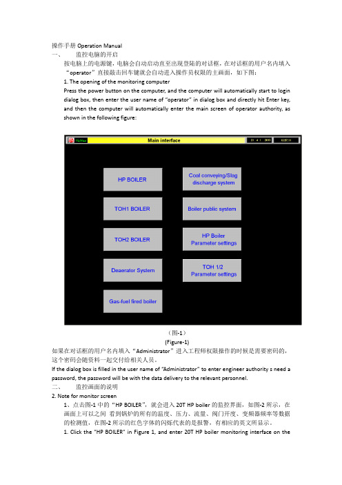
操作手册Operation Manual一、监控电脑的开启按电脑上的电源键,电脑会自动启动直至出现登陆的对话框,在对话框的用户名内填入“operator”直接敲击回车键就会自动进入操作员权限的主画面,如下图:1. The opening of the monitoring computerPress the power button on the computer, and the computer will automatically start to login dialog box, then enter the user name of “operator” in dialog box and directly hit Enter key, and then the computer will automatically enter the main screen of operator authority, as shown in the following figure:(图-1)(Figure-1)如果在对话框的用户名内填入“Administrator”进入工程师权限操作的时候是需要密码的,这个密码会随资料一起交付给相关人员。
If the dialog box is filled in the user name of “Administrator” to enter engineer authority s need a password, the password will be with the data delivery to the relevant personnel.二、监控画面的说明2. Note for monitor screen1、点击图-1中的“HP BOILER”,就会进入20T HP boiler的监控界面,如图-2所示,在画面上可以之间看到锅炉的所有的温度、压力、流量、阀门开度、变频器频率等数据的检测值,在图-2所示的红色字体的闪烁代表的是报警,有相应的英文所显示。
2024版Windows7基础操作培训教程

目录•Windows7系统概述•Windows7基本操作•Windows7系统设置与优化•Windows7常用软件安装与使用•Windows7安全与防护•Windows7维护与故障排除Windows7系统概述Windows7的发展历程01Windows7的起源作为Windows Vista的继任者,Windows7在设计和功能上进行了诸多改进。
02开发过程微软在开发过程中广泛征求用户意见,对Windows7进行了大量优化和调试。
03发布时间2009年10月22日,Windows7正式发布,随后在全球范围内推广。
Windows7的版本与功能版本类型01Windows7分为家庭版、专业版、企业版和旗舰版等多个版本,满足不同用户需求。
功能特点02Windows7引入了新的任务栏、窗口管理、搜索功能等,提高了用户体验。
与旧版兼容性03Windows7在保持与旧版软件兼容的同时,也支持新的技术和标准。
01020304处理器1GHz或更快的32位或64位处理器。
内存1GB(32位)或2GB (64位)RAM。
硬盘空间16GB(32位)或20GB (64位)可用硬盘空间。
显卡支持DirectX9的显卡,带有WDDM1.0或更高版本的驱动程序。
Windows7的硬件要求Windows7基本操作退出Windows7点击“开始”按钮,选择“关机”选项,在弹出的菜单中选择“关机”或“重新启动”。
启动Windows7按下计算机主机电源按钮,等待Windows7启动完成并显示桌面。
启动与退出Windows桌面图标与任务栏设置桌面图标设置在桌面空白处右击,选择“个性化”进入个性化设置窗口,在左侧选择“更改桌面图标”,在弹出的窗口中勾选需要在桌面显示的图标。
任务栏设置右击任务栏空白处,选择“属性”,在弹出的窗口中可以进行任务栏的位置、大小、自动隐藏等设置。
窗口的基本操作打开窗口双击桌面图标或从开始菜单中启动应用程序,即可打开相应的窗口。
PC7电子控制器操作维护手册说明书
SERIAL NUMBER (located on top of product):Phone: 800-669-1303 or 801-561-0303 Fax: 801-255-2312e-mail:**************************PC7 PUMP CONTROLLEROperation / MaintenanceManualCONTENTS1INSTALLATION (3)1.1UNPACKING (3)1.2UTILITIES / HOOK-UP (3)2OPTIONS (5)2.1UNIT IS AVAILABLE IN BOTH PFA AND PP CONSTRUCTION (5)3START-UP (6)3.1PERFORMANCE CHARTS (7)4MAINTENANCE (8)4.1PREVENTIVE MAINTENANCE SCHEDULE (8)4.1.a Preventive Maintenance Record (9)4.2RECOMMENDED SPARE PARTS (10)4.3TOOLS (10)4.4PARTS ILLUSTRATION – PC7 (10)4.5PARTS LIST – PC7F (11)4.6PARTS LIST – PC7P (11)4.7CLEAN-UP (12)4.8DISASSEMBLY (12)4.9ASSEMBLY (12)5156161 INSTALLATION1.1 UNPACKINGAfter unpacking, the components should be checked for damage that may haveoccurred during shipment. Damage should be reported to the carrierimmediately.The following items should be included within the shipping container:Qty Item Description1 PC7F or PC7P PC7 PUMP CONTROLLER1 PC7-Manual Manual, PC7 Pump Controller1.2 UTILITIES / HOOK-UPThe controller can be mounted by any of three methods. It can be bolted to a wall or deck using the snap on base slots as shown below using four ¼”(6mm) boltsin the pattern shown below.MTD0616CONTROLLER - BOTTOM VIEWMTD0617MTD0618 PUMP INSTALLATION - BACK PUMP INSTALLATION - TOP1HEAD2MTD0619ADJUSTMENT SCREWAir Inlet:3/8” Flaretek (3/8” OD TUBING)Air Supply: 20-80 PSIG (1.4 – 5.4 BAR), CLEAN DRY AIR OR NITROGEN. Head Ports: 3/8” Flaretek (3/8” OD PFA TUBING)Recommended Maximum Operating Levels: 80 psig (5.4 bar)ATTENTION: The controller should be operated with clean, dry air or nitrogen. Particulate, water and oils in the air supply can damage the controller.2 OPTIONS2.1 UNIT IS AVAILABLE IN BOTH PFA AND PPCONSTRUCTIONThe PFA unit exterior parts are molded using PFA (Fluoroplastic) and the shuttle assembly is constructed of PEEK & PPS. The PFA unit is intended for severeapplications and for compliance with FM4910.The PP unit exterior parts are molded using Polypropylene (Polyolefin) and theshuttle assembly is constructed of PEEK & PPS. This unit is intended as a lower cost option with similar service life where exposure to oxidizing acids is limited.3 START-UP∙Controller air supply pressure must be regulated to a maximum of 80 psig.∙Open the fluid suction (IN) line valve, if necessary.∙Open the fluid discharge (OUT) line valve, if necessary.∙Adjust the speed control screw fully Clockwise (CW) until fully retracted.Warning! Do not apply too much torque to screw or damage may result.CONTROL SCREWCAUTION: When handling potentially dangerous fluids under pressure, the pump and its fittings should be placed in an enclosure away from operators.3.1 PERFORMANCE CHARTSPumping capacity is a function of air supply pressure and volume, suction head, suction line restrictions, discharge head, discharge line restriction, and fluidspecific gravity and viscosity.20 0 8020 1/2 3040 0 13540 2 7060 0 19060 2 8080 0 24080 2 110NOTE: Test information is based on specific conditions and limited sampling.Use for general reference only. This information is preliminary and may bechanged at a future date.4 MAINTENANCE4.1 PREVENTIVE MAINTENANCE SCHEDULEThe following maintenance schedule is recommended to optimize pump performance and minimize failures.Adhering to the recommended preventative maintenance schedule along with periodic inspection of the pump will ensure continued efficient operation and overall reliable pump performance.It is recommended that the Preventive Maintenance Record (Section 4.1.a) be copied, maintained and kept with this unit for future reference.PC7 MaintenanceReplacement InspectionComponent / Comments1 Y e a r2 Y e a r6 m o n t h s1 Y e a r2 Y e a rX Fitting Nuts (Connections) P/N (9002914) X X Detent Legs P/N (305-PD) X X Shuttle Spool P/N (305-PJ) X X Spring Bar P/N (305-QA)XMuffler Media (PC7 Controller) P/N (305-FR)4.1.a Preventive Maintenance RecordCompany Name: _____________________________________________________Company Address:_____________________________________________________Number:________________SerialProduct: _________________Date: ________ Tech: _____ Notes: ________________________________________________________________________________Date: ________ Tech: _____ Notes: ________________________________________________________________________________Date: ________ Tech: _____ Notes: ________________________________________________________________________________Date: ________ Tech: _____ Notes: ________________________________________________________________________________Date: ________ Tech: _____ Notes: ________________________________________________________________________________Date: ________ Tech: _____ Notes: ________________________________________________________________________________Date: ________ Tech: _____ Notes: ________________________________________________________________________________Date: ________ Tech: _____ Notes: ________________________________________________________________________________Date: ________ Tech: _____ Notes: ________________________________________________________________________________Date: ________ Tech: _____ Notes: ________________________________________________________________________________Date: ________ Tech: _____ Notes: ________________________________________________________________________________Date: ________ Tech: _____ Notes: ________________________________________________________________________________Date: ________ Tech: _____ Notes: ________________________________________________________________________________Date: ________ Tech: _____ Notes: ________________________________________________________________________________Date: ________ Tech: _____ Notes: ________________________________________________________________________________Date: ________ Tech: _____ Notes: ________________________________________________________________________________Date: ________ Tech: _____ Notes: ________________________________________________________________________________Date: ________ Tech: _____ Notes: ________________________________________________________________________________Date: ________ Tech: _____ Notes: ________________________________________________________________________________Date: ________ Tech: _____ Notes: ________________________________________________________________________________Date: ________ Tech: _____ Notes: ________________________________________________________________________________Date: ________ Tech: _____ Notes: ________________________________________________________________________________Date: ________ Tech: _____ Notes: ________________________________________________________________________________Date: ________ Tech: _____ Notes: ________________________________________________________________________________4.2 RECOMMENDED SPARE PARTSThere are no recommended spare parts for the Purus 20 pump due to it’s welded and sealed construction. However there are spare parts available for rebuild ofthe PC7 pump controller.PC7 Pump Controller305-PD 4 EA LEG, DETENT305-QA 2 EA SPRING BAR, DETENT305-P016 2 EA SEAL, PTFE, 1.75 X 1.33 X .02 (PC7F ONLY!)305-P015 2 EA SEAL, PTFE, 1.82 X 1.33 X .02 (PC7P ONLY!)305-PJ 1 EA SPOOL, SHUTTLE305-P040 1 EA SCREW, SPEED ADJUSTMENT305-P048 1 EA FERRULE, PTFE305-FR 5 EA PAD, MUFFLER4.3 TOOLSThe only tool requirements are a Phillips #2 and Straight screwdriver.4.4 PARTS ILLUSTRATION – PC74.5 PARTS LIST – PC7FILLNOPART NO QTY DESCRIPTION PM YEAR #MATERIAL1 305-P049 1 NUT, COMPRESSION,PVDF, 3/8 PVDF2 305-P048 1 FERRULE, PTFE, PC7 PTFE3 305-P047 1 CAP,PFA,ADJUST,PC7 PFA4 305-040 1 SCR,ADJUST,PC7 PVDF5 305-PD 4 LEG,DETENT,PC7 DELRIN6 305-QA 2 SPRINGBAR,DETENT,OSCILLATOR PEEK7 305-QB 1 PLATE,SUPPORT,PC7 PVDF8 305-P007 2 SCR,NYLON,#8-32x.31,SLOVHD NYLON9 305-PJ 1 SPOOL,SHUTTLE,OSCILLATOR PEEK10 305-P016 2 SEAL,PTFE,GORTEX,1.75x1.33x.02 PTFE11 305-P050 1 RING,SPLIT,SINGLE TURN,PTFE,-016PTFE12 305-P014 2 FTG,PVDF,3/8"ME PVDF13 AK058 1 ASSY,SHUTTLESLEEVE CERAMIC14 305-P013 2 TUBE,TRANSFER,PFA PFA15 305-P009 3 NUT,PVDF,FLR,3/8T PVDF16 305-PA 1 BODY,OSCILLATOR,PFA,PC7 PFA17 AW036-01 2 ORIFICE, PRESS-IN .024 PEEK18 305-P011 1 CAP,PFA,PC7 PFA19 305-FR 4 PAD,MUFFLER,PP,25MICRON PP20 305-QF 1 BASE,PFA,PC7 PFA4.6 PARTS LIST – PC7PILLNOPART NO QTY DESCRIPTION PM YEAR #MATERIAL1 305-P052 1 NUT, COMPRESSION, PP, 3/8 PP2 305-P048 1 FERRULE, PTFE, PC7 PTFE3 305-P046 1 CAP,PP,ADJUST,PC7 PP4 305-P040 1 SCR,ADJUST,PC7 PVDF5 305-PD 4 LEG,DETENT,PC7 DELRIN6 305-QA 2 SPRINGBAR,DETENT,OSCILLATOR PEEK7 305-QB 1 PLATE,SUPPORT,PC7 PVDF8 305-P007 2 SCR,NYLON,#8-32x.31,SLOVHD NYLON9 305-PJ 1 SPOOL,SHUTTLE,OSCILLATOR PEEK10 305-P016 2 SEAL,PTFE,GORTEX,1.75x1.33x.02 PTFE11 305-P050 1 RING,SPLIT,SINGLE TURN,PTFE,-016PTFE12 305-P045 2 FTG,PP,3/8"ME PP13 AK058 1 ASSY,SHUTTLESLEEVE CERAMIC14 305-P013 2 TUBE,TRANSFER,PFA PFA15 305-P009 3 NUT,PVDF,FLR,3/8T PVDF16 305-P006 1 BODY,OSCILLATOR,PPPC7 PP17 AW036-01 2 ORIFICE, PRESS-IN .024 PEEK18 305-P002 1 CAP,PFA,PC7 PFA19 305-FR 4 PAD,MUFFLER,PP,25MICRON PP20 305-P005 1 BASE,PP,PC7 PP4.7 CLEAN-UPDue to possible contamination all components must be flushed clean andneutralized before disassembly to prevent fluid contact with personnel.4.8 DISASSEMBLYTo disassemble PC7 pump controller for service, remove controller from pump by disconnecting the flare fittings on the PC7 from the transfer tubes connecting it to the pump.Caution: For safety make sure air supply to PC7 has been shut off prior toremoval of supply line.∙Unscrew Adjustment Cap from controller body and carefully twist shuttle spool from sleeve by rotating cap assembly.∙Gently remove the cap seal from the seat inside the cap to prevent any damage or possible scratches to sealing surface. Replacement of seal isrecommended after service.∙Use a straight blade screwdriver to remove the two retaining screws from the support plate. Next loosen compression nut and ferrule from adjustmentscrew and gently push the adjustment screw out of the cap by pressing onthe end. This assembly contains the only serviceable items. See explodedassembly for part numbers and part locations.∙Inspect parts for wear and replace if necessary.4.9 ASSEMBLY∙To reassemble detent, twist the adjustment screw into the support plate and then insert 2 each spring bars into slots as per figure 1.MTD0630Figure 1∙Next insert 2 each detent legs as shown in Figure 1 and open spring bars to lock assembly as shown in Figure 2.MTD0631Figure 2∙Lastly insert 2 ea. detent legs into slots on shuttle spool as shown in Figure 3 and insert into previous assembly.MTD0632Figure 3∙ See completed detent assembly illustrated in Figure 4.MTD0633Figure 4∙Insert detent assembly into adjustable cap as shown here and install 2 each retaining screws.MTD0634Figure 5Note: Do not over tighten screws. Cap threads are easily stripped.∙Install ferrule onto adjustment screw with the longest taper toward the adjustment cap. Then install compression nut onto cap per figure 6.MTD0635Figure 6∙Tighten nut finger tight to engage compression seal.∙Insert Gortex seal into thread end of adjustable cap assembly onto sealing land as shown.MT D0636Figure 7∙Screw cap assembly with seal onto the open end of body assembly carefully inserting shuttle spool into valve body and engage air seal completely.∙Cap requires only moderate installation torque to activate seal. Over tightening can dislocate seal gasket preventing oscillation of the controller valve.5 TROUBLESHOOTINGController Will Not Operate or Cycles ErraticallyCause: Solution:∙PC7 cap seal failure ∙Remove caps from PC7 and replace PTFE cap seal.∙Debris in shuttle valve ∙Isopropyl alcohol clean the shuttle sleeve and spool assy.∙Insuffisant air pressure ∙Increase regulated supply pressure or check control valvesfor proper operation.∙Rotate PC7 speed control screw CW until it stops. Thenreadjust for correct speed.∙Adjustment Screw Seal failure ∙Replace adjustment screw assy.∙Spring bar failure ∙Spring bar needs replacement if not flat.6 WARRANTYPC7F OR PC7P CONTROLLERTREBOR International, Inc. warrants to the purchaser of new equipmentmanufactured by TREBOR to be free from defects in material and workmanshipwhen used for its intended purpose under normal operating conditions, andmaintained according to the Operation/Maintenance Manual.TREBOR’s obligation under this warranty is limited to repairing or replacing, atTREBOR’s option and at the TREBOR factory, any part or parts thereof whichshall, within 1 year after delivery thereof to the original purchaser, bedemonstrated to TREBOR’s satisfaction to have been defective. This warrantymay be transferred to subsequent owners. The warranty period is based on the original ship date from the factory. All warranty related freight costs shall beborne by the customer.Excessive wear to pump components caused by pumping abrasive solutions orchemicals, as well as damage caused by ingesting foreign objects shall not becovered by this warranty.This warranty shall not apply to any equipment which, in the judgment ofTREBOR, shall have been repaired or altered outside TREBOR’s factory in anyway, so as to affect its performance or reliability; subjected to misuse, negligence or accident; or used other than in accordance with TREBOR’s printedinstructions.There are no terms, conditions or warranties, expressed, implied orstatutory, of merchantability, fitness, capacity, or otherwise, of the goodsordered, other than, or different from, the warranty set forth above. Thiswarranty takes precedence over any other warranty, expressed or implied.TREBOR neither assumes, nor authorizes any other party to assume for it, anyliability in connection with said equipment except as set forth above.。
正版windows7使用手册(产品说明)
欢迎使用 Windows 7。
4
Wi性
Windows 7 的兼容性很好,在设计之初,Windows 7 的兼容性就被视为重要一部分。使用 Windows 7,您无需担心 Windows 7 的兼容性问题,因为在中国,已有 92%的主流软件、92% 的硬件以及 95%的网站及互联网应用与 Windows 7 良好兼容。从网上支付方面来说:在 Windows 7 发布之前,就已经达到了“6+1”的兼容目标:中国银行、农业银行、工商银行、建设银行、招 商银行、交通银行+支付宝,从而能够充分满足您网上购物、网上交易等需求。而且,微软还将 继续悉心聆听市场反馈,不断完善 Windows 7 的兼容性,以保证您享有更加顺畅的用户体验。 Windows XP 模式
有了 Windows 7,您可以使新的事情成为可能。您会找到新的方式来随时随地享受和分享 您的音乐、照片、视频和录制的电视节目,而不管它们的存储方式和存储位置。Windows 7 提 供了更多的方式,使您能在任何位置有效地访问您的数据和工作,包括更容易连接到无线网络。 我们还增加了新的办法,使您能够通过触摸屏与电脑交互。电脑在家庭中的作用是不断变化的。
如果您想解有关 Windows 兼容性中心的更多信息,您可以访问以下网址: /windows/compatibility
Windows 7的硬件配置要求(推荐配置)
常有用户问我们这样一个问题,Windows 7 对硬件配置的要求高吗?配置不高的 PC,能运 行 Windows 7 么?
轻松创建家庭网络充分发挥设备作用越来越多的家庭开始拥有一台以上的电脑和多种数字设备您一定希望家庭中的这些电脑打印机和各类数字设备能以最便捷的方式连接在一起让您可以与您的家庭成员快乐分享文件视频音乐共度美好时光而不要因为技术障碍影响到您与家人的交流
2024年度windows7操作系统ppt课件pptx
04
Windows 7的高级功能
2024/3/23
20
多任务处理与窗口管理
多任务处理
Windows 7支持同时运行多个应 用程序,用户可以在不同任务之
间轻松切换,提高工作效率。
窗口管理
Windows 7提供了多种窗口管理 功能,如窗口的缩放、移动、最 大化、最小化和关闭等。用户可 以通过简单的鼠标操作或快捷键
10
安装Windows 7的步骤与注意事项
注意事项
确保计算机满足最低硬件要求
在安装前备份重要数据
2024/3/23
11
安装Windows 7的步骤与注意事项
选择正确的安装版本(32位或64位) 在安装过程中注意选择合适的分区和格式化选项
2024/3/23
12
配置Windows 7的网络与设备
2024/3/23
连接网络
选择合适的网络连接方式,如有 线或无线连接,并输入正确的网 络凭据
网络共享
配置文件和打印机共享,以便在 局域网内共享资源
13
配置Windows 7的网络与设备
• 远程桌面:启用远程桌面功能,以便远程管理和控制计算 机
2024/3/23
14
配置Windows 7的网络与设备
01
02
03
安装驱动程序
3
文件与文件夹的搜索
包括在文件夹中搜索文件或文件夹、使用高级搜 索等。
2024/3/23
18
控制面板的使用
2024/3/23
控制面板的打开方式
包括通过开始菜单、运行命令等方式打开控制面板。
控制面板的组成
包括控制面板中的各种选项和工具。
控制面板的常用操作
Windows 7操作系统使用文档
升级途径
至: 从: Windows XP 或更低版本 Windows Vista (RTM) Windows Vista Starter (SP1+) Windows Vista Home Basic (SP1+) Windows Vista Home Premium (SP1+) Windows Vista Business (SP1+) X X X X X X X X X 是 X X X X X 是 是 X X X X X X 是 X X X X X 是 X X X 是 是 是 简易版 家庭普通版 家庭高级版 专业版 企业版 旗舰版
进度条:无需将应用程序切换回前台就可查看进度信息。
任务栏通知区域:默认情况下,此区域中可见的图标仅为四个系统图标和时钟。
显示桌面:任务栏最右侧的细竖条是新的“显示桌面”按钮。
跳转列表:可快速访问应用程序相关的最常见任务,以及用户在运行该应用程序时最有可能用到的文档、媒体或其他文 件。
“开始”菜单
Windows 7---安全性
新增控制面板界面(四个选项) 改进了 UAC 设臵屏幕 降低了 UAC 提示频率 增加了无需管理权限即可执行的
Windows 操作
减少了重复通知
最佳做法 使用默认 UAC 设臵或更高设值。 除非客户请求或要排除故障, 否则不要建议客户降低 UAC 级别。 确保客户使用标准用户帐户。
窗口预览功能
更改概述
工具
操作中心 * 疑难解答*
Windows 7---疑难解答工具
说明
通过这个新的疑难解答控制面板,可以访问与 PC、Windows 和疑难解答程序的状态 相关的消息,这些消息可帮助诊断和解决许多常见问题。 此界面提供自动诊断和修复实用程序。