AX2227+CW6639模块使用说明书_
卓荣集成电路 AX222 SD MMC MS读卡器控制器 产品说明书

[AX222-UM-002]AX222 SD/MMC/MS读卡器控制器产品说明书版本 0.0.22011年8月卓荣集成电路科技有限公司地址: 香港沙田香港科学园科技大道西6号集成电路开发中心7楼705-707室高性能 SOCUSB 特性•支持的USB 规格为 v2.0•支持的USB 存储类规格为v1.0SD 卡特性•支持的SD 规格为 v2.0•支持的 SDHC 卡容量可达 32GB •支持写保护•支持热拔和移除MMC 卡特性•支持的MMC 规格为v4.2•支持的MMC 卡容量可达 32GB •支持热拔和移除MS/MSPRO 特性•支持的MS 规格的v1.43•支持的MSPRO 规格为v1.03•支持MS PRO-HG Duo 的规格为 v1.01•支持 1/4/8 位的总线模式•最大支持卡容量 32GB LED 驱动 IO 双电压调节器AX222 SD/MMC/MS读卡器控制器初稿 0.0.2AX222 SD/MMC/MS读卡器控制器产品说明书 1 结构概况1.1 系统架构图1-1: AX222 硬件架构AX222 SD/MMC/MS 读卡器控制器 Rev 0.0.2产品说明书2 引脚定义2.1 引脚分配Table 2-1: 焊盘坐标引脚编号名称X轴 (um)Y轴 (um)1UVDD33T39.838.72UVDD33P123.838.73DP208.438.74DM292.938.75UVSS33T376.2 38.76UVSS33P460.538.77UVSS18559.938.78UVDD18645.738.79TCLK824.938.7初稿 0.0.2AX222 SD/MMC/MS读卡器控制器产品说明书10P1.2/LED973.238.711VSS1093.138.712VDD50/NC1170.538.713VDD501238.438.714VREG331328.138.715VREG181423.338.716SDV331529.038.717P1.3/MSIN1474.2942.718P1.4/SDIN1385.5942.719P1.0/CLK1295.3942.720P1.1/CMD/BS1203.0942.721P1.6/WP1114.8942.722P0.7/NC1034.8942.723P0.6/NC949.4942.724P0.5/NC863.3942.725P0.4/NC777.9942.726P1.7/NC693.5942.727VSSIO608.0942.728P0.3/D3523.2942.729VDDIO436.8942.730P0.2/D2352.2942.731P0.1/D1265.5942.732P0.0/D0176.6942.733P1.5/Test86.3942.72.2 焊盘说明AX222 SD/MMC/MS 读卡器控制器 Rev 0.0.2产品说明书DM4IO USB D-UVSS33T5P PHY analog ground (Double-bond with UVSS33P)UVSS33P6P PHY analog ground (Double-bond with UVSS33T)UVSS187P 1.8V Digital power groundUVDD188P 1.8V Digital power inputTCLK9I Test mode external clockP1.2/LED10IO Port 1 pin 2 – LED0 indication or serial portVSS11P Regulator groundVDD50/NC12P NCVDD5013P Regulator 5V power inputVREG3314P Regulator 3.3V power output (for external capacitor connection)Note: VREG33 is short-circuit with VDDIOVREG1815P Regulator 1.8V power output (for external capacitor connection)SDV3316P SD/MMC/MS card output 3.3V powerP1.3/MSIN17IO Port 1 pin 3 – MS card insertion indication signal P1.4/SDIN18IO Port 1 pin 4 – MDC card insertion indication signal P1.0/CLK19IO Port 1 pin 0 – MDC/MS clockP1.1/CMD/BS20IO Port 1 pin 1 – MDC command, MS BSP1.6/WP21IO Port 1 pin 6 – MDC write protectP0.7/NC22IO Port 0 pin 7 – NCP0.6/NC23IO Port 0 pin 6 – NCP0.5/NC24IO Port 0 pin 5 – NCP0.4/NC25IO Port 0 pin 4 – NCP1.7/NC26IO Port 1 pin 7 – NCVSSIO27P Digital groundP0.3/D328IO Port 0 pin 3 – MDC/MS data 3VDDIO29P Digital I/O 3.3V power inputP0.2/D230IO Port 0 pin 2 – MDC/MS data 2P0.1/D131IO Port 0 pin 1 – MDC/MS data 1P0.0/D032IO Port 0 pin 0 – MDC/MS data 0P1.5/Test33IO Port 1 pin 5 – Test Pin初稿 0.0.2AX222 SD/MMC/MS读卡器控制器产品说明书 3 裸片原理图3.1 SD/MMC/MS 4位模式位模式的有效焊盘图3-1: SD/MMC/MS 4AX222 SD/MMC/MS 读卡器控制器 Rev 0.0.2产品说明书图3-3:SD/MMC/MS 4位模式的原理图注意:1.根据用户需要选择R1,C1,C3和C4。
GM222 数字量输出扩展模块说明书
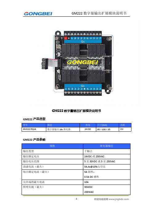
GM222数字量输出扩展模块说明书
GM222产品选型
型号描述供电尺寸(mm)功耗GM222-RQ16数字量输出16x继电器24VDC95×108×353W
GM222产品参数
规格继电器输出
输出类型干触点
输出额定电压24VDC或250VAC
输出电压范围5至30VDC或5至250VAC
浪涌电流(最大)5A,4s@10%占空比
每点额定电流(最大)5A阻性;
0.5A DC感性
公共端的最大电流10A
照明负载(最大)30WDC
200WAC
接通电阻(最大)0.2Ω
隔离(光电隔离)线圈到触点:1500VAC,1分钟断开到接通/接通到断开最大延时10ms
机械寿命10,000,000
(无负载)
触点寿命100,000(额定负载)
GM222数字量输出扩展模块接线示意图
GM222数字量输出扩展模块输出结构图
扩展模块地址分配
连接好扩展模块,点击S7软件菜单栏的“PLC”,点“信息”,弹出信息表,一行代表一个设备。
里面写着起始地址,以此为准。
常见问题:扩展模块地址是由主机上电时分配的,如果扩展模块供电顺序晚于主机,地址分配会出现错误,正确的操作:断电后,等30秒钟,彻底断电,连接好所有扩展模块,重新上电。
外形尺寸
注:黑色底壳背后有卡扣,可挂标准导轨。
星源北斗 HG-RF02-B MAX2769 射频模块 产品说明书

HG-RF02-BMAX2769射频模块产品说明书V1.0 (支持5V直插TCXO,支持BD B1)北京星源北斗导航技术有限责任公司2012 年 4 月 5 日Item ContextAuthor hgLast Update 2012-4-5Version 1.0Copyright(c) 北京星源北斗导航技术有限责任公司密级对外交流更多详细信息请致电星源北斗咨询!公司地址:北京市海淀区温泉镇显龙山路19号北辰香麓雅庭A座218室电话及传真:************QQ:5024141邮箱:***************1 产品简介表1 产品价格表产品价格HG-RF02-B基本组件HG-RF02-B 1000元可选配配件5米长GPS天线40元可搭配使用的其他硬件HG-RE03-B开发板(EP3C55) HG-FPGA01底板(EP3C55) 3480元2000元HG-RF02-B射频模块是在总结HG-RF02射频模块基础上设计的管脚兼容产品,模块经过HG-RE03-B接收机验证块,信号质量优异,原来HG-RF02的GPS SAW滤波器用470pF 电容替代,接收信号不受限制,适合于GPS、BD、Galieo、Glonass单系统研制。
HG-RF02-B需要外部提供3.3V和5V的电源,5V电源为射频部分供电,需要保证电源的稳定性。
2 产品特性图1 HG-RF02-B射频模块HG-RF02基本硬件如上图所示,特性如下:1.射频芯片:MAX27692.TCXO频率:16.368MHz3.默认采样率:16.368MHz4.默认中频中心频点:4.092MHz5.供电方式:3.3V和5V外接电源6.支持5V直插晶振:封装长16mm,宽8mm7.对外接口:射频输入:MMCX*2,1个有源天线输入口,1个无源天线输入口。
时钟输出:GPSCLKI支路数据:I1、I0Q支路数据:Q1、Q0SPI接口:PGM、SCLK、SDATA、nCS其他:nIDLE、nSHDN、ANTFLAG、LD、TSENS8.体积:50mm×26mm3 接口关系图2 HG-RF02-B对外接口图(符合HG-RFDIS标准)4 尺寸图图3 HG-RF02-B尺寸图(默认单位为mm)5 装箱清单1、HG-RF02-B硬件模块1块;2、配套文档:HG-RF02-B使用说明书;3、MAX2769 SPI配置参数文档:BD B1配置;6 服务条款1、半个月内如产品硬件有质量问题可免费更换;2、提供3个月QQ技术支持;3、本产品允许客户把产品提供的配置参数用于最终产品中,但不允许将本产品提供的配置参数提供给任何第三方;。
ZM602系列Wi-Fi模块用户手册说明书

ZM602系列Wi-Fi模块用户手册Wi-Fi模块UM01010101 1.2 Date:2022/9/16类别内容关键词ZM602模块,Wi-Fi+BLE,用户手册摘要©2022 Guangzhou ZHIYUAN Electronics Co., Ltd.修订历史文档版本日期原因V1.00 2022.04.25 首次发布V1.01 2022.08.18 新增产品实物图;新增特色功能说明;更新产品选型表;优化快速使用说明;优化BLE数据透传说明;新增数据通道说明;新增串口命令:读取设备MAC地址、读取STA连接状态、读取连接到本设备的STA列表目录1. 产品简介 (1)1.1 概述 (1)1.2 产品特性 (1)1.3 典型应用 (2)1.4 产品选型表 (2)2. 快速使用说明 (3)2.1 与设备建立连接 (3)2.2 设置Wi-Fi工作模式 (4)2.3 使用设备连接其他热点 (5)3. 产品功能 (7)3.1 Wi-Fi数据透传 (7)3.1.1 场景一:模块数据互传 (7)3.1.2 场景二:模块与笔记本电脑进行数据互传 (12)3.2 BLE数据透传 (13)4. 工作模式 (16)4.1 网络工作模式 (16)4.1.1 数据通道 (16)4.1.2 TCP Server模式 (17)4.1.3 TCP Client模式 (18)4.1.4 UDP Client模式 (18)4.1.5 UDP Server模式 (18)4.1.6 MQTT Client模式 (19)4.2 Wi-Fi工作模式 (19)4.2.1 AP模式 (19)4.2.2 STA模式 (19)4.2.3 AP+STA模式 (19)5. 配置设备 (20)5.1 网页配置 (20)5.1.1 登录设备网页 (20)5.1.2 系统 (20)5.1.3 专家 (20)5.1.4 串口 (20)5.1.5 网络 (21)5.1.6 无线 (21)5.1.7 热点 (22)5.1.8 用户登录 (22)5.1.9 系统管理 (22)5.1.10 软件更新 (22)5.2 蓝牙快速配网 (23)5.3 串口协议指令 (25)5.3.1 基本原则 (25)5.3.2 封包结构 (26)5.3.3 命令列表 (28)5.3.4 事件列表 (28)5.3.5 命令解析 (29)6. 免责声明 (42)1. 产品简介1.1 概述ZM602系列Wi-Fi模块是广州致远电子有限公司基于博流BL602系列芯片开发的高性能Wi-Fi+BLE模块产品。
Modicon Premium自动化平台-TSXCAY22运动控制模块说明书
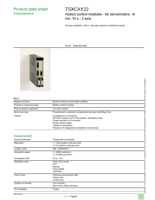
i s c l a i m er : T h i s d o c u m e n t a t i o n i s n o t i n t e n d e d a s a s u b s t i t u t e f o r a n d i s n o t t o b e u s e d f o r d e t e r m i n i n g s u i t a b i l i t y o r r e l i a b i l i t y o f t h e s e p r o d u c t s f o r s p e c i f i c u s e r a p p l i c a t i o n sProduct data sheetCharacteristicsTSXCAY22motion control modules - for servomotors - 8ms..10 s - 2 axisProduct availability : Stock - Normally stocked in distribution facilityPrice* : 5340.60 USDMainRange of productModicon Premium Automation platform Product or component type Motion control modules Product specific application For servo motorsServo loop type Proportional to overshoot compensation and gain switching 2 ms ChecksConsistency of commandsEncoder coupling, servo drive present, emergency stop Proper execution of movement Sensor power supply Validity of parametersPresence of voltage/sensor feedback counter inputComplementarySpeed profile path Trapezoidal or parabolic Resolution <= 1000 position units per point >= 0.5 position units per point Length of axis 256...32000000 P Acquisition speed >= 54000 points/mn <= 270000 points/mn Acceleration time 8 ms...10 s Operating modeDirect drive mode OFF ManualFOLLOWER AutomaticType of axisFollowing axis dynamic ratio Infinite axis Limited axisFunction of module Cut on the flyServo drive offset correction I/O modularity2 axesInput compatibility Absolute encoder SSI output 12...25 bitsIncremental encoder 10...30 V totem poleIncremental encoder 5 V DC RS422With 2-wire/3-wire sensor (24 DC) auxiliary inputAbsolute encoder parallel output ABE7CPA11Clock frequency200 kHz SSI absolute encoderIncremental encoder frequency x1500 kHzIncremental encoder frequency x 41000 kHz in counting250 kHz in inputPower dissipation in W7.2...11.5 WInput type Current sink auxiliary input conforming to EN/IEC 1131 Type 2Resistive counter inputResistive servo drive control input conforming to EN/IEC 1131 Type 1 Input logic PositiveInput voltage24 V 8 mA auxiliary input24 V 8 mA servo drive control input5 V 18 mA counter inputInput voltage limits<= 5.5 V counter input19...30 V auxiliary input19...30 V servo drive control inputVoltage state 1 guaranteed>= 11 V auxiliary input>= 11 V servo drive control input>= 2.4 V counter inputCurrent state 1 guaranteed>= 3.5 mA servo drive control input>= 3.7 mA counter input>= 6 mA auxiliary inputVoltage state 0 guaranteed<= 1.2 V counter input<= 5 V auxiliary input<= 5 V servo drive control inputCurrent state 0 guaranteed<= 1 mA counter input<= 1.5 mA servo drive control input<= 2 mA auxiliary inputInput impedance270 Ohm counter input3000 Ohm auxiliary input3000 Ohm servo drive control inputNumber of outputs 2 analogue output static2 reflex output static conforming to EN/IEC 611312 servo drive validation output relayAnalogue output range+/- 10...24 VAnalogue output resolution13 bits + signLSB value 1.25 mV analogue outputOutput voltage24 V DC reflex output24 V DC servo drive validation outputOutput voltage limits19...30 V reflex output5...30 V servo drive validation outputNominal output current0.5 A reflex outputMaximum output current 1.5 mA analogue output200 mA servo drive validation output625 mA reflex outputMinimum load 1 mA 1 VVoltage drop< 1 V at state on reflex outputLeakage current< 0.3 mA reflex outputSwitching time< 5 ms for servo drive validation< 500 µs for reflex outputOutput compatibility Positive logic DC inputs (resistance <= 15 kOhm) reflexShort-circuit protection Current limiter reflex outputThermal tripping reflex outputOutput overload protection Current limiter reflex outputThermal tripping reflex outputOutput overvoltage protection Zener diode between outputs and 24 DC reflex outputReverse polarity protection Reverse diode on supply reflex outputLocal signalling 2 LEDs green axis diagnostics available1 LED green module operating (RUN)1 LED red external fault (I/O)1 LED red internal fault, module failure (ERR)Electrical connection1 connector HE-10 20 pins for aux inputs, reflex output, for external sensor and preactuator power supply1 connector HE-10 20 pins for servo drive ctrl inputs + for ext power supply of servo drive inputs/outputs1 connector SUB-D 9 for an analogue output (speed reference)2 connectors SUB-D 15 for an incremental or absolute encoder Current consumption1100 mA 5 V DC 15 mA 24 V DC11...20 mA 24 V DC on 10/30 V absolute encoder module Module format StandardProduct weight1.06 lb(US) (0.48 kg)EnvironmentProtective treatmentTCAmbient air temperature for operation 32...140 °F (0...60 °C)Ambient air temperature for storage -13...158 °F (-25...70 °C)Relative humidity 5...95 % without condensation Operating altitude<= 6561.68 ft (2000 m)Ordering and shipping detailsCategory22558 - TSX PREMIUM, ATRIUM & PL7 PRO Discount Schedule PC22GTIN00785901123675Nbr. of units in pkg.1Package weight(Lbs) 2.21Returnability N Country of originFROffer SustainabilitySustainable offer status Not Green Premium productRoHS (date code: YYWW)Compliant - since 0806 - Schneider Electric declaration of conformity Schneider Electric declaration of conformity REAChReference not containing SVHC above the threshold Reference not containing SVHC above the threshold Product end of life instructionsNeed no specific recycling operationsContractual warrantyWarranty period18 monthsDimensions DrawingsStandard and Extendable Racks for Modules MountingDimensions of Modules and Racks(1) With screw terminal block modules.(2) Maximum depth for all types of modules and their associated connectors.Connection of Speed Reference Signals Connector PinoutConnection of Counting SignalsConnectors PinoutsConnection of Sensors/Pre-actuators and Encoder Power Supply, without Variable Speed ControllerHE10 Connector PinoutThe auxiliary inputs/outputs are allocated the following functions:●I0 = cam reference point input,●I1 =emergency stop input (stop if there is no current in the input),●I2 = adjusting input,●I3 = adjustment input,●Q0 = reflex output (static output),●0 V = shared auxiliary inputs and reflex outputs.Connection of the Variable Speed Controller Signals Connector PinoutThe axis command modules implement basic management of the signals necessary for correct operation of the variable speed controllers. Thereis only one connector, regardless of the number of axis command module channels.COMx – VALVARx: potential free contact to validate variable speed controller OK_VARx: variable speed controller input check 24 V – 0 V sensor power supplyNOTE: Each channel uses a potential free closing contact.。
AX2227+CW6639模块使用说明书_

APB8202 CW6639说明书目录1模块综述 (3)2APB8202 CW6639模块特性 (3)2.1 模块基本特性 (4)3模块尺寸 (4)4引脚定义 (5)4.1 APB8202CW6639模块引脚描述 (5)4.2 AX2227引脚介绍 (7)5功能应用 (11)6电气特性 (11)6.1 方案功耗 (11)7应用领域 (11)8应用原理图 (12)9已知现象 (12)10特别注意 (12)1模块综述蓝牙作为无线领域的一个标杆,应用越来越广,蓝牙产品也越来越多样化,随着手机蓝牙的普及,蓝牙产品深入到各个领域,蓝牙多媒体设备更是受到了大众的青睐,成为主流。
APB8202 CW6639是建荣集成倾力打造的一款高性能蓝牙模块,是以与蓝牙移动电话配合使用为设计目的,采用的是蓝牙V2.1+EDR的规范,可兼容3.0及以下版本蓝牙规范的应用,而且支持免提模式或者高品质音频模式切换;具有应用简便,音质优越,灵敏度高,体积小,传输距离远等特点,在无障碍遮挡的环境下,测试工作距离10M 以上。
模块面积更小,局限小,方案适用性更强。
APB8202 CW6639模块,模型如图所示。
6637模块2APB8202 CW6639模块特性•基于CLASS 2 功率等级,采用Bluetooth 2.1+EDR 规范,兼容蓝牙3.0及以下版本应用,传输速度可达到3Mbit/s。
•支持L2CAP/A2DP(AVCTP/AVDTP/AVRCP) ,用来接收立体声音频信号,通过协议可以控制音频发射端的上下曲操作。
•支持HSP/HFP(Handsfree profile),具有免提功能,可以进行语音通讯。
•支持简易配对,不需输入配对密码,支持自动回连功能。
•更宽的工作电压范围(2.2V~5V)。
•采用调试好的PCB 天线,无需重新匹配天线。
•支持低功耗模式sniff mode,stop mode。
2.1模块基本特性Items DescriptionBluetooth standard V2.1+EDRDimension 16mm x 13.97mm x 2mmVoltage 2.2V ~ 5.0VTemperature -20℃ ~ +70 ℃Storage Temperature -40℃ ~ +150℃Frequency Range 2402MHz ~ 2480MHz(total 79 channels) Channel Frequency 2402+1(K-1)MHz, K=1, 2, 3 (79)Maximum RF Transmit Power +4dBmAntenna gain 0dBiReceive Sensitivity -80dBm3模块尺寸模块类型尺寸APB8202 CW663916mm x 13.97mm x 2mm4引脚定义4.1APB8202 CW6639模块引脚描述脚号名称电气特性说明1XTAL P Analog Input预留外部26MHz 晶振输入(采用外部晶振时使用,不使用时,底板勿留焊盘)2XTAL O Analog Input预留外部26MHz 晶振输入(采用外部晶振时使用,不使用时,底板勿留焊盘)3VIN Power模块电源输入(3.3V)4GND Power数字地5TXD Digital I/O APB8202 CW6639模块串口数据发送6RXD Digital I/O APB8202 CW6639模块串口数据接收7CTS Digital I/O APB8202 CW6639模块串口控制8 RSTB Digital I/O 蓝牙复位脚9 TP5 Digital I/O 测试脚10 TP4 Digital I/O 测试脚11 TP3 Digital I/O 测试脚12 TP2 Digital I/O 测试脚13 TP1 Digital I/O 测试脚 TEST EN14 GND Digital Output 数字地特别说明:模块IO 为3.3V 电源系统,外灌电压请不要超过3.3V ,否则IC 可能工作不稳定。
CW-MX系列音频模块接口说明说明书

CW-MX-AMI Audio Module Interface.Controls two CW-EVX-25E/50E/100E amplifier modules in remote distribution panels. Onerequired when adding back up amplification to a Dual channel system. Uses an addition slot on a CW-MX-MBR.CW-MX-ASC Audio System Control.Provides digitally stored Message Control. Has two RS232 com ports.CW-MX-BA Back-up Amplifier switching relay.One required for each Distributed Amp whenautomatic switching / redundant amplification is needed.On a single Channel system the back up amplifiercan be located in any CW-MX-DP panel. On a Dual Channel system an additional CWMX-AMI card,and CW-EVX-#E Amplifier assembly is required(the # represents the largest power amplifier in the system 25/50/100).CW-MX-BAB Back-up Amplifier switching relay Class “A”One required for each Distributed Amp plus the “spare” amplifier when automatic switching /redundant amplification is needed Class “A ” wiring.On a single Channel system the ”spare” amplifier can be located in any CW-MX-DP panel. On a Dual Channel system an additional CWMX-AMI card,and CW-EVX-#E Amplifier assembly is required (the # represents the largest power amplifier in thesystem 25/50/100).CW-MX-BRK Break Out Card Used to provide terminal connections from 10 Pin ribbon cable for wiring termination. (2 required)Needed when Dual Channel Back-Up Amplification is required.CW-MX-DCC Data Communications ControllerA DCC is located in the Master Panel and eachDistributed Panel the DCC is the connection point for the NETCOMM communications. The Data loop must be wired style 6 or 7 (Style 7 preferred) (must have return data loop). Replacement Card, typically preprogrammed from the factory.CW-H MX High Rise Voice EvacuationSystem ComponentsCW-MX-BABMenvierNovember 2017CW-MX-FO Fiber Optic Transceiver Provides termination for Fiber Opticcommunications between the Master Panel andthe Distributed PanelsCW-MX-FO7 Fiber Optic Style 7 cardMaster Panel Fiber Optic card (1 per system) required when Style 7 Fiber Optic communications is used. The CW-MX-FO7 card converts the secondary (style 7) data loop to a data signal that can be senton the Fiber Optic secondary loop.CW-MX-FPI Fire Phone Interface.Provides 4 supervised Class “B” Fire Phone circuits in distributed panel (4 max 16 circuits). When more then one is used in a CW-MX-DP panel a CW-MX-FPO card is required for each.CW-MX-FPO Fire Phone Output Adapter.Extra terminal card that must be used withthe 2nd, 3rd & 4th CW-MX-FPI cards in aDP panel.CW-MX-FPO2 Fire Phone Output Adapter.Extra break out card that must be used with the2ND, 3RD & 4TH CW-MX-FPI cards in a DP panel. This card aligns all 4 Fire Phone circuits vertically. CW-MX-FPR Fire Phone Relay.Warden station reverse polarity relay for NYCap plications.CW-MX-II Input Interface Card.Hardwired conventional control input interface/trigger. Required when using any triggers other the CW-HMX Intelligent Interface. Provides 16inputs and control for up to 7 additional CW-MX-XI input cards (128 inputs). System capacity for up to16 CW-MXII cards (2048 inputs). TTL or dry contract input. Also accepts a reverse polarity NACcircuit trigger.CW-MX-INB Isolated Network BridgeNetwork interface when a Master Panel is needed to communicate with remote Master Panels running their own systems.CW-MX-IPI Isolated Printer InterfaceMaster Panel interfaced board for RS232 data into HCWMX system using a Fire Panel printer port, also has a parallel printer port for connection a Fire Panel printer. Interfaces to CW-MX CW-MX-ASC.CW-MX-ISO Isolator RS232Ground Isolator card: Isolates the groundfrom the RS232 connection from The Fire Alarm Panel.CW-MX-LLC LED Lamp Card32 LED only card for annunciation atMaster PanelCW-MX-MBK Mother Board Relays.Provides 4 Class “B” speaker Loop outputs. A maximum of 2 CW-MX-MBK cards provide 8 “Class B” or 4 Class “ A” Speaker circuits per Distributed panel. One additional required for 8 Class “B” or 4 Class “A” Distributed Panel Speaker Circuits.CW-MX-MBR Mother Board Remote.Provides the 4 card slots (can be extended to MAX 7)for CW-MX-AMI & CW-MX-FPI and 2 CW-MX-MBK speaker cards (Speaker Loop Zonesplitter function)2CW-MX-FOCW-MX-FOCW-MX-FO7 CW-MX-FPO2CW-MX-FPI CW-MX-ISOCW-MX-IPICW-MX-LLCCW-MX-MBRCW-MX-IIMenvierNovember 2017CW-MX-MFI Master Fire Phone cardMaster Panel’s Fire Phone Card connects to the DCC to provide Fire Fighter Phone communication.CW-MX-MFA Master Fire phone Assembly Master Panel’s replacement Fire Phone Handset, Plate and Interface PC board.CW-MX-MMC Master Microphone Control Provides Microphone, System Control andstatus display.CW-MX-NYS “FIRE” sign.Master Panel mounted flashing FIRE sign. Utilizes a single row of the Master Panel.CW-MX-OI Output Interface CardHardwired control output interface. Provides 16 outputs and control for up to 7 additional CW-MX-XO output cards (128 outputs). System capacity for up to 16 CW-MX-OI cards (2048 outputs). TTL output.CW-MX-PWR Master Panel Power Supply. Regulated 24VDC at 1.5 Amps and battery charging system for use with Master Panel.CW-MX-SLC Switch / LED Card.16 switches and LED’s for manual control at Master Panel.CW-MX-SSC Switch Scan Card.Controls up to 8 Switch/LED Cards (128 Switches). Multiple (16) CW-MX-SSC cards can be used for a System capacity of 2048 Switches. Field Additions or Replacement only.CW-MX-XI Extended Input Interface.Provides 16 additional inputs per card. Used with CW-MX-II card, recommend a separate mounting cabinet.CW-MX-XO Extended Output Interface. Provides 8 outputs per card. Used with CW-MX-OI card, recommend a separate mounting cabinet.CW-EVX-ZAB Zo ne Adapter CardConverts 4 Class B speaker circuits into 8Class B Speaker circuits, requires a separate mounting cabinet.3CW-MX-MFIMFICW-MX-MFAFIRECW-MX-NYSSSCCW-MX-XICW-EVX-ZABNovember 2017CW-MX-XOEatonEMEA Headquarters Route de la Longeraie 7 1110 Morges, Switzerland Eaton.eu© 2017 EatonAll Rights Reserved November 2017Eaton is a registered trademark.All other trademarks are property of their respective owners.CW-EVX ATM Audio Matching Circuit A udio T elephone M odule600-ohm balance Line telephone or paging module. Used to connect to an existing telephone or paging system into t he CW-HMX Voice System. 600 ohm, 25/70 VRMS inputCW-EVX-ZA Class A Zone Adapter Card Converts 4 Class B speaker circuits into4 Class A Speaker circuits, requires a separate mounting cabinet.CW-EVX-ATMCW-EVX-ZAMenvierNovember 2017。
艾莫迅wifi电缆手册说明书

AMSamotion帮助一百万家企业实现自动化智能制造WiFi无线PLC编程器使用手册(对应艾莫迅串口转TCP工具v6.0版本)[第一版]艾莫迅自动化科技(东莞)有限公司目录第一章WiFi电缆使用情景 (1)1-1.现场版WiFi电缆 (2)1-2.远程版WiFi电缆 (2)1-2-1.远程模式 (2)1-2-2.现场版AP模式 (3)1-2-3.现场版ST模式 (3)第二章艾莫迅串口转TCP工具应用 (4)2-1.软件的安装 (4)2-2.软件使用说明 (6)第三章指示灯及按键说明 (9)3-1.指示灯说明 (9)3-2.按键说明 (9)第四章WiFi电缆通讯步骤 (10)4-1.现场版WiFi电缆通讯 (10)4-2.远程版WiFi电缆通讯 (11)4-2-1.远程模式 (11)4-2-2.现场版AP模式 (15)4-2-3.现场版ST模式 (15)第五章通讯问题分析 (17)5-1.通用情况分析 (17)5-2.按通讯模式分析 (18)第六章应用拓展 (19)6-1.MODBUS开关量模块的无线控制 (19)6-2.组态王与PLC连接 (22)6-3.连接扩展 (24)6-4.定制开发 (24)附录 (25)第一章WiFi电缆使用情景通过WiFi电缆可对PLC/触摸屏等控制设备,以无线的方式现场短距离(空旷处理论30m)或远程,进行程序的上下载及监控,按不同功能分不同使用情景。
1-1.现场版WiFi电缆该电缆Model名称不带“-R”,WiFi名称数字部分不以0开头,上电PWR红灯常亮,仅此一种通讯模式,应用在现场范围30m内(理论值,受环境或干扰等因素可能降低)的电脑编程软件与PLC的通讯,电脑连接电缆的WiFi后无法上网1-2.远程版WiFi电缆Model名称带“-R”,WiFi名称数字部分以0开头,含有3种通讯模式:远程模式、现场版AP模式、现场版ST模式1-2-1.远程模式该模式为出厂通讯模式,当WiFi电缆和装有上位机的电脑均连外网时,即可在异地进行远程控制PLC。
- 1、下载文档前请自行甄别文档内容的完整性,平台不提供额外的编辑、内容补充、找答案等附加服务。
- 2、"仅部分预览"的文档,不可在线预览部分如存在完整性等问题,可反馈申请退款(可完整预览的文档不适用该条件!)。
- 3、如文档侵犯您的权益,请联系客服反馈,我们会尽快为您处理(人工客服工作时间:9:00-18:30)。
APB8202 CW6639说明书目录1模块综述 (3)2APB8202 CW6639模块特性 (3)2.1 模块基本特性 (4)3模块尺寸 (4)4引脚定义 (5)4.1 APB8202CW6639模块引脚描述 (5)4.2 AX2227引脚介绍 (7)5功能应用 (11)6电气特性 (11)6.1 方案功耗 (11)7应用领域 (11)8应用原理图 (12)9已知现象 (12)10特别注意 (12)1模块综述蓝牙作为无线领域的一个标杆,应用越来越广,蓝牙产品也越来越多样化,随着手机蓝牙的普及,蓝牙产品深入到各个领域,蓝牙多媒体设备更是受到了大众的青睐,成为主流。
APB8202 CW6639是建荣集成倾力打造的一款高性能蓝牙模块,是以与蓝牙移动电话配合使用为设计目的,采用的是蓝牙V2.1+EDR的规范,可兼容3.0及以下版本蓝牙规范的应用,而且支持免提模式或者高品质音频模式切换;具有应用简便,音质优越,灵敏度高,体积小,传输距离远等特点,在无障碍遮挡的环境下,测试工作距离10M 以上。
模块面积更小,局限小,方案适用性更强。
APB8202 CW6639模块,模型如图所示。
6637模块2APB8202 CW6639模块特性•基于CLASS 2 功率等级,采用Bluetooth 2.1+EDR 规范,兼容蓝牙3.0及以下版本应用,传输速度可达到3Mbit/s。
•支持L2CAP/A2DP(AVCTP/AVDTP/AVRCP) ,用来接收立体声音频信号,通过协议可以控制音频发射端的上下曲操作。
•支持HSP/HFP(Handsfree profile),具有免提功能,可以进行语音通讯。
•支持简易配对,不需输入配对密码,支持自动回连功能。
•更宽的工作电压范围(2.2V~5V)。
•采用调试好的PCB 天线,无需重新匹配天线。
•支持低功耗模式sniff mode,stop mode。
2.1模块基本特性Items DescriptionBluetooth standard V2.1+EDRDimension 16mm x 13.97mm x 2mmVoltage 2.2V ~ 5.0VTemperature -20℃ ~ +70 ℃Storage Temperature -40℃ ~ +150℃Frequency Range 2402MHz ~ 2480MHz(total 79 channels) Channel Frequency 2402+1(K-1)MHz, K=1, 2, 3 (79)Maximum RF Transmit Power +4dBmAntenna gain 0dBiReceive Sensitivity -80dBm3模块尺寸模块类型尺寸APB8202 CW663916mm x 13.97mm x 2mm4引脚定义4.1APB8202 CW6639模块引脚描述脚号名称电气特性说明1XTAL P Analog Input预留外部26MHz 晶振输入(采用外部晶振时使用,不使用时,底板勿留焊盘)2XTAL O Analog Input预留外部26MHz 晶振输入(采用外部晶振时使用,不使用时,底板勿留焊盘)3VIN Power模块电源输入(3.3V)4GND Power数字地5TXD Digital I/O APB8202 CW6639模块串口数据发送6RXD Digital I/O APB8202 CW6639模块串口数据接收7CTS Digital I/O APB8202 CW6639模块串口控制8 RSTB Digital I/O 蓝牙复位脚9 TP5 Digital I/O 测试脚10 TP4 Digital I/O 测试脚11 TP3 Digital I/O 测试脚12 TP2 Digital I/O 测试脚13 TP1 Digital I/O 测试脚 TEST EN14 GND Digital Output 数字地特别说明:模块IO 为3.3V 电源系统,外灌电压请不要超过3.3V ,否则IC 可能工作不稳定。
4.2 AX2227 引脚介绍P21VDDHP VDDDAC DACR VCM DACL AVSSP36P 04P 01P 33P 00P 06P 07P 16P 14P13IRTWKO IRTOSCO IRTOSCI VDDIO P37P15VDDCORE DVSSP10P12P27P11U S B D PU S B D M P 26VDDIRT P 05P 34P 30P 31P 35P 23P 24P 25P 02P 17P 32P 03P 22P20Pin assignment for LQFP48LQFP48 pin descriptionPin No.LQFP48NameTypeFunction 1P27I/OEMID7 SDDAT00SPI0DODI0 SPI0DO0 GPIO 2P21I/OEMID1IISDI0 SDCLK0 GPIO 3P20I/OEMID0IISBCLK SDCMD0 GPIO4P36I/OVPG33Pin No.LQFP48 Name Type FunctionAUXR1GPIO5 VDDLDO PWP LDO 5V Power6 VDDIO PWR IO 3.3V Power7 VDDHP PWR HeadPhone 3.3V Power8 VDDDAC PWR DAC 3.3V Power9 DACR AO DAC Right Channel10 VCM AO DAC Bandgap voltage reference11 DACL AO DAC Left Channel12 VSSDAC GND DAC Ground13 P03 AI MICIN1 VCMBUF AUXL214 P02 AI MICIN0 AUXR215 P01 I/O AUXR0 SDDAT2 UART0TX1 GPIO16 P00 I/O AUXL0 SPI0DI2 SDDAT1 UART0RX1 GPIO17 P14 I/O PWM3 CAP3 SDDAT3 SPI0DODI2 SPI0DO2 GPIO18 P33 I/O ADC0 PWRWKUP LVDDET CLKO GPIO19 P04 I/O ADC2INT0SPI1DO1 SPI1DODI1 PWM1Pin No.LQFP48NameTypeFunction SPI0DODI1 SPI0DO1 GPIO 20P05I/OADC3 INT1SPI1CLK1 CAP0 SPI0CLK1 GPIO 21P06I/OADC1 SPI1DI1TMR1 TMR0 SPI0DI1 GPIO 22P07I/OINT3CAP1 GPIO 23P16I/OADC6 PWM2 IISREFCLKAMIN CAP2 UART0TX0 GPIO 24 P17 I/O TMR2IISWS GPIO25 VSSCOM GND Digital Ground 26 VDDCORE PWR Digital 1.2V Power 27 P37 I/O AUXL1 GPIO 28 P13 I/O ADC5 GPIO 29 P12 I/O GPIO 30 P11 I/O GPIO 31 P10 I/O EMIWR GPIO 32 VDDIRT PWR IRT 5V Power 33IRTOSCIAIIRTC Oscillator InputPin No.LQFP48 Name Type Function34 IRTOSCO AO IRTC Oscillator Output 35 IRTWKO I/O IRTC Wake up 36P15I/OTMR3 GPIO 37P32I/OSPI1DO0SPI1DODI0 SDDAT01 GPIO 38P31I/OSPI1DI0SDCMD1 GPIO 39P30I/OADC4SPI1CLK0 SDCLK1 GPIO 40P34I/OINT2 PWM0SPI0CLK2 UART0RX0 GPIO 41P26I/OEMID6SPI0CLK0 GPIO 42P25I/OEMID5SPI0DO3 SPI0DI0 GPIO 43P24I/OEMID4IISDO1 GPIO 44P23I/OEMID3IISDI1 GPIO 45 P22 I/O EMID2IISDO0 GPIO46 USBDM I/O USB Negative Input/output 47 USBDP I/O USB Positive Input/output 48P35I/OUDSW GPIOI: input; O: output; PWR: power; GND: ground; AO: Analog Output; AI:Analog Input;NC: not connect5功能应用模块配合建荣集成的一个解码芯片AX2227使用,能够实现MP3解码,语音通话等一系列功能。
•可以SD/TF卡,支持WMA/MP3格式解码。
•支持个性提示音。
•可以直接驱动LED/LCD段码屏/串口屏。
•支持按键开关机。
•可支持语音通讯应用,支持HFP(Handsfree profile),具有免提功能。
•支持扩展功能,方案支持在SDK 上进行二次开发,应用更灵活。
6电气特性6.1方案功耗工作状态未配对已连接播放未连接进入低功耗暂停进入低功耗电流(mA)40~507590~925~206~7.87应用领域•蓝牙小音箱•蓝牙MP3 Boombox•蓝牙扬声器•家用蓝牙音响•高品质立体声音响•蓝牙音频通讯设备•蓝牙点烟器.....8应用原理图模块应用原理图详见说明书附件:APB8202 CW6639 应用原理图9已知现象1.部分手机不支持淡入淡出的功能,所以在播放暂停和上下曲切换的时候会存在POP 声2.蓝牙断线检测为非实时检测,所以,在蓝牙音箱关闭一段时间后,手机端才断开连接3.部分手机在播放3S内按上一曲,会回到当前歌曲的初始位置,从而需要连按两次才能具有上一曲功能4.部分手机不支持简易配对,例如塞班系统的手机,则配对时需要输入配对密码000010特别注意1.蓝牙模块的位置尽量不要走线,特别是在PCB天线附近位置,需要留下净空区或开槽2.通常将蓝牙模块的天线尽量靠近PCB 的边缘位置放置3.模块的工作电压范围为2.2V~5V,低于或者高于工作电压范围均容易造成模块工作不稳定。