ZDB智能电机保护器的安装与维护-4页word资料
ZDB控制器操作说明书

操作说明本装置调试完毕投入运行,监视跟踪电容电流的变化,自动调整补偿参数。
当发生接地故障时自动补偿并记录接地信息。
该装置设置了六个键:复位键、F1、F2、F3、F4和自检键。
其中复位键是系统直接进入复位状态的功能键,任何时候按下此键,系统均进行复位,程序重新进入正常监控状态。
自检键是系统进入自检状态的功能键。
其他键为功能复用键,具体功能见液晶屏上的提示。
下面将分别介绍其中的主要界面和具体的操作方法。
1、开关机顺序开机:先投入消弧线圈,再投入控制装置关机:先关控制装置,再关消弧线圈2、开机运行开机后显示如图1界面,停留8秒进入测量状态,如图2所示。
图1 ZDB-2A主界面图2在此界面中“02-01-18/16:38:34”表示当前的时间是2002年1月18日16时38分34秒。
此为实时时钟,接地故障发生与否不影响此时钟。
“开口电压”右面的“001.2V"表示当前母线的开口零序电压值,无论是否发生接地故障,此值总是实时显示该段母线的开口零序电压值。
“正在检测”表示了该装置的状态“电容电流自动跟踪动态补偿装置”表示产品的名称;“天津市航博公司”是该装置的开发商;“F1参数F2调时F3查档F4消音”是对操作者提供的操作提示,其具体操作将在下面作详细的介绍。
控制器处于测量电网电容电流的状态,缓慢递加施加直流励磁,此期间控制柜的“助磁电流”表指针也缓慢上升直至最大。
然后再缓慢下降至最小。
此过程是判断消弧线圈在控制过程中是否会与电网发生串联谐振,以便程序进行相应的处理。
然后“助磁电流”指针在某处变化很慢约20秒时间,进行精确测量电容电流。
如果电容电流比消弧线圈的下限还要低,控制器就报下限报警,如图3所示;如果电容电流比消弧线圈的上限还要高,控制器就报上限报警,如图4所示;电容电流在消弧线圈上下限之内,表示系统可以控制,如图5所示。
图3图5处于下限时说明对电网电容电流估计过高,这种情况一般不要投运。
处于上限则说明对电网电容电流估计不足,这种情况可以投运,但不能达到残流小于5A的要求。
ZDB-Z-10.5-J 过电压保护器

⑴电缆外端裸露的连接线鼻子相互之间距离,应满足不同电压等级的不同相带电导体之间保持的最小安全距离的要求;
⑵ZDB电缆线之间的安全距离及ZDB电缆线与不同相母线(或柜体)之间的安全距离应不小于该型保护器相间距离(应在电缆电缆拉紧状况下);
182
3
ZDB-Z-7.6/19
7.6
6
15
13.5~18
20.4
19
19
197
ZDB-Z-6/W
250
406
5
ZDB-Z-12.7/31
12.7
10
25
22.5~30
33.8
31
31
131
197
3
ZDB-Z-12.7/W
250
406
5
ZDB-Z-42/110
42
35
75
67~90
105
119
119
工频试验电压分别加在被测试品的A和D、B和D、C和D、A和C、B和C、以及A和B上,缓慢调高试验变压器的输出电压,同时观察电压表及数字电流表A1,ZDB间隙未击穿放电时,数字电流表A1的读数会随着电压升高而逐渐增大。当试验变压器的输出电压达到ZDB的动作值时,ZDB间隙被击穿放电,数字电流表A1的数值将突增,此时试验变压器的高压输出电压值即为该ZDB的工放值。
⑶ZDB高压电缆长度要根据安装位置进行选择,长短要适当,过长时可将该相电缆捆扎固定在同相母排(线)上,严禁将不同相电缆捆扎在一起;
⑷安装时严禁手提电缆.同时要注意避免高压电缆被锐器割破。
二、产品结构/特点
ZDB-Z/10.5-J三相组合式过电压保护器的电气原理如图一所示,图中FR为高能容氧化锌非线形电阻,JX为放电间隙,由于采用对称结构,其中任意三个可分别接入A、B、C三相,另一个接地线。
电动机保护器说明书

电动机保护器说明书电动机保护器说明书1.概述微机监控电机保护器适用于AC380V、AC660V低压系统,作为低压异步电动机和增安型电动机的保护、监测和控制的新一代智能化综合装置。
除了先进的电动机保护、监控功能,还提供了设备运行和跳闸的记录以及额定参数等重要信息,并且采用现场总线方式结构,为现代化的设备管理带来很大的便利;广泛用于石油、化工、电力、冶金、煤炭、轻工、纺织等行业。
符合标准:GB3836.3-2000、GB14048.4-2003、IEC2552.特点●“tE时间保护”符合有关增安型防爆电动机过载保护的国家标准(GB3836.3-2000)●交流采样,测量A、B、C三相电流及控制回路电压●现场显示电动机运行状态,保存三次电动机故障跳闸记录●一路保护输出,一路自定义继电器输出,一路4~20mA电流输出或RS485接口●高清晰度宽温液晶显示,并具有背景光,跟随电动机运行状态和用户要求实时显示●三相电流不平衡、断相、过压、欠压、自启动等功能用户可取可舍●采用E2PROM存储技术,实现参数电设定,掉电后设定参数仍保存下来,勿须再设定●采用RS485通信总线,可广泛用于各种监控系统作为带有电机保护及控制的智能化监控单元●一机多用,可取代电流表、电压表、热继电器、电流互感器、时间继电器和漏电继电器等3.主要功能保护功能:过流、堵转、断相、三相电流不平衡、过压、欠压、短路、漏电(选配)等故障保护测量功能:三相电流、控制回路电压的测量和显示通用功能:增安型电动机保护、三相异步电动机保护、馈线保护,三种保护装置通用通信功能:通过本保护器的RS485接口与上层系统通信。
总线接口支持参数设置、控制及监测等功能,支持Modbus通信协议。
一般采用RS485总线接口进行物理连接,通常上位机或PLC设备作为主站,本保护器作为子站。
电流输出:4~20mA电流输出,20mA对应的电流值可设。
4.型号说明微机电动机保护监控装置适用于AC660V及以下低压系统,作为低压电动机馈线终端的保护、监测和控制的新一代智能化综合装置。
电机智能保护器配置手册说明书
How to configure, monitor, and control Motor Insight via Modbus, DeviceNet, and PROFIBUSApplicationMotor Insight T is an advanced motor protective relay with thermal motor overload, supply,and load protection; configurable ground fault detection; power monitoring; an intuitive user interface; and optional communications. The optional communications allow for remote control and reset of faults, and remote monitoring of numerous operating and configuration parameters. The communication modules also include inputs that can be usedto bring the status of sensors or switches backto the system controller, as well as outputs to control the contactor or turn on pilot lights.OverviewThe industrial networks supported by the Motor Insight relay are all open networks. This means that there are many software tools already available that can be used to configure the device over these networks. Each of the supported networks will be discussed in this document, including suggestions for various configuration tools, many of which are free downloads from the Internet. In many cases, the network tools supplied by the manufacturerof the network master can be used to configure any device on that network.Overview of Modbus T, DeviceNet E and PROFIBUS TFor most applications, the Motor Insight relay parameters can be easily configured using its intuitive user interface. Then, the communication network master can be used to control and monitor the device during operation. This network master reads status information from each slave device and writes control information. The communication interface modules forMotor Insight allow control for the following:1. Remote reset of a fault2. Remote trip3. Control of on-board field outputs Numerous parameters are available to be monitored from Motor Insight, including:1. Device status bits2. rms current IA3. rms current IB4. rms current IC5. rms current average6. rms voltage VAB7. rms voltage VBC8. rms voltage VCA9. rms voltage average10. Total kW11. Voltage unbalance percent12. Current percent13. Apparent power factor14. Residual ground current deciamps15. Frequency16. Overload thermal pile17. Trip reason18. Overload status19. Error code20. Field inputsThe following is a discussion concerning the third-party software tools available for the open networks supported by Motor Insight. ModbusMotor Insight supports both Modbus RTU and Modbus ASCII modes, as well as baud rates from 9600 to 115.2K baud. It will communicate with any Modbus master.The unique aspect of Modbus is that special configuration tools are typically not necessaryas they are with many other industrial networks. The reason is that Modbus requires Modbus Data Register addresses for all parameters in all Modbus devices. This allows a Modbus master to easily read and write data to a Modbus slave device for configuration, control, and monitoring purposes. Motor Insight is no different. It has assigned a Modbus Data Address to all available parameters. This information is publishedin the Motor Insight overload and monitoring relays user manual, publication MN04209001E.Eaton Corporation Electrical Sector1111 Superior Ave. Cleveland, OH 44114United States877-ETN-CARE (877-386-2273) © 2010 Eaton CorporationAll Rights ReservedPrinted in USAPublication No. AP04209004E / Z9775 August 2010PowerChain Management is a registered trademark of Eaton Corporation.All other trademarks are property of their respective owners.Application Paper AP04209004E Effective August 2010How to configure, monitor, and control Motor Insight via Modbus, DeviceNet,and PROFIBUSIf a third-party Modbus software package is desired to configureor verify the configuration or operation of Motor Insight, there are numerous software tools available. Many of these tools are free downloads, such as ModScan. Others can be found by simply searching the Web for Modbus Software Tools.Eaton has a line of electronic operator interface devices called HM i.A program for a 4-inch HM i is available as a free download from /motorinsight or via this direct link. This program communicates via Modbus to multiple Motor Insight devices. It contains screens for configuring, monitoring, and controlling upto 16 Motor Insights from a single HM i. To obtain the HM i software needed to download the program to an HM i, visit / electrical. Then, click the “Tools & Downloads” link. Next, select “Software Downloads.” On the next page, under the Products drop-down, select “Operator Interface...” and then select “HM i Operator Interface Configuration Software.” Also note that the HM i software allows for changing the HM i program so it can be downloaded to any size HM i: 4-, 6-, 8-, or 10-inch unit.Another source of available Modbus tools can be found on the official Modbus Web site: .DeviceNetUnlike Modbus, where all parameters in a device have a data address assigned to them, DeviceNet slave devices use input and output assemblies. Each input assembly will include the same status bits indicating operational status of the device. The various input assemblies differ by the additional data that can be monitored with each. The Motor Insight relay has five different input assemblies. Two of these input assemblies allow the user to select the parameters to monitor. The various output assemblies are for control. They provide the ability to reset faults, trip the overload, and turn the outputs on-board the DeviceNet module on and off. DeviceNet is an open network that requires a software tool to configure slave devices and to map their data into the scan list of the master. The manufacturer of the DeviceNet master will provide a software tool to map slave devices into the scan list of the master so the system controller can control and monitor each Motor Insight. Motor Insight contains an intuitive user interface for configuration, but when on a DeviceNet network, it can be configured by any third-party DeviceNet commissioning tool as well. The DeviceNet specification requires that all DeviceNet products have an eds file (electronic data sheet). This file is a text file that is used to uniquely define each parameter in the device. DeviceNet commissioning tools are designed with the ability to import eds files for any valid DeviceNet slave device. The software tool can then be used to configure the device. There are two eds files and an icon file available for Motor Insight. They may be downloaded from/motorinsight. These files can then be imported into any valid DeviceNet commissioning software, such as:1. Eaton’s CHStudio E2. Eaton’s ELCSoft (DNET CONFIG Tool)3. Rockwell’s RSNetWorx E for DeviceNetCHStudio is a free download from the Eaton Web site; searchfor CHStudio and download the software and activation code.It can be used to configure any DeviceNet slave device, but notthe network master.ELCSoft is the programming software for the Eaton PLC line called ELC. This PLC line includes a complete DeviceNet master, the ELC-CODNETM module. The commissioning software is included in the ELCSoft programming software. It can configure any DeviceNet slave device by importing the eds file for the device and can fully configure the ELC-CODNETM DeviceNet master module.The manufacturer of the network master typically supplies the software tools needed to configure the master. RSNetWorxfor DeviceNet can be purchased from Rockwell or a Rockwell distributor. Motor Insight eds files can be imported into RSNetWorx for DeviceNet, allowing the software to configurethe Motor Insight and a Rockwell DeviceNet master.Once all slave devices on a DeviceNet network have been configured and mapped into the DeviceNet master’s scan list, the master will continuously poll the slave devices, like the Motor Insight, writing control data to them and monitoring various parameters. Motor Insight has more data available to monitor than any other overload relay of its type. This information is published in the Motor Insight overload and monitoring relay user manual, MN04209001E.Another source of available DeviceNet tools can be found on the official DeviceNet Web site: .PROFIBUSPROFIBUS is very similar to DeviceNet in that the network configuration tools are typically supplied by the manufacturer of the PROFIBUS master. There is also a file for PROFIBUS similar to the eds file for DeviceNet, called a GSD file. All valid PROFIBUS slave devices must have a GSD file. This file is imported into the PROFIBUS commissioning tool or the programming software, allowing the software to configure the device and map its I/O data so the PROFIBUS master can poll the slave devices for control and monitoring purposes. These PROFIBUS tools are supplied bythe manufacturer of the PROFIBUS master. The GSD file may be downloaded from /motorinsight. This file can then be imported into any valid PROFIBUS software tool, such as Siemen’s SIMATIC Software. Other PROFIBUS network product vendors are Woodhead Connectivity, Bihl+Wiedemann GmbH and PROCENTEC. Another source of available PROFIBUS tools can be found on the official PROFIBUS Trade Organization Web site: /.Supporting documentationMotor Insight User Manual MN04209001E Motor Insight DeviceNet Instructional Leaflet IL04209005EMotor Insight Modbus Instructional Leaflet IL04209004EMotor Insight PROFIBUS Instructional Leaflet IL0420900XEELC System Manual MN05003003EELC-CODNETM Instructional Leaflet IL05001003EHM i User manual MN04802014EAdditional helpIn the event that additional help is needed, please contact the Technical Resource Center at 1-877-ETN-CARE (386-2273).。
电机安装操作和维护规范
电机的安装操作和维护规范1.到货检验A.验收签收收货单前请详细检查是否有零部件缺少或损伤,如果有,应让货运公司在货单上注明。
如果发现隐蔽的损伤,马上通知货运并请他作进一步的检查。
B.搬运起吊前,要确保拧紧吊环,电机吊环只能用来吊电机及标准附件,如果有多个吊环,应使用相对的吊环,吊绳或链条与水平面的角度要大于45°。
C.储存电机必须储存在清洁干燥的区域,应避免高温、潮湿和振动。
储藏温度从50°F到120°F,最大相对湿度不超过60%。
若是长期储存,应每三个月测量一次绕组的绝缘电阻和环境温度,检查一次涂漆表面和裸露金属表面是否腐蚀。
注意:要移开排水孔塞子,并保持排水孔在最低点。
所有的通风孔和排水孔必须起作用。
2.安装只有具备资格的人能进行这项操作。
A.位置电机放置点环境温度应不超过40℃(104°F),并保持良好的通风和干净的空气。
(更详细的要求见用户手册)B.排水孔塞排水孔塞应该移开(XT电机例外)C.电源确认电机铭牌数据和控制器输出一致,并按照控制器指令手册进行安装和连接。
D.安装电机必须被安装在刚性基础上。
不良的基础结构可能导致电机和基础之间产生共振。
(关于螺栓的固定要求见用户手册)E.连接选择合适的起动器和过电流保护装置。
根据控制器指令手册,将引线标记U/T1、V/T2、W/T3连接到合适的控制器输出端。
F.转向改变任意两相接线即可改变电机转向。
G.热保护温控开关必须连接到适当的控制器电路。
电机必须可靠接地。
H.驱动将电机和负载连接以前检查电机转向。
操作前确保所有的防护装置被安装。
3.运行起动以前应注意以下几点:a)移去所有不用的键和松散的旋转部件,以防止它们飞出伤人,并将罩和防护装置放回原处。
b)当RPM AC电机作为驱动系统的一部分时,参考驱动系统操作手册指令。
编码器反馈必须连接成闭环。
除了上述注意事项外,起动前必须检查以下项目。
按照控制器指令手册要求关掉并移开电源根据控制器指令手册要求确认直流母线电压为零电机内部必须清洁干燥接线应该牢固c)如果可能的话将电机和驱动设备断开。
电动机安装、运行、维护说明书

Installation • Operation • Maintenance InstructionsInduction MotorsTABLE OF CONTENTSINSPECTION. . . . . . . . . . . . . . . . . . . . . . . . . . . . . . . . . . . . . . . . . . . . . . . . . 4STORAGE. . . . . . . . . . . . . . . . . . . . . . . . . . . . . . . . . . . . . . . . . . . . . . . . . . . 4INSTALLATION. . . . . . . . . . . . . . . . . . . . . . . . . . . . . . . . . . . . . . . . . . . . . . . 4OPERATION. . . . . . . . . . . . . . . . . . . . . . . . . . . . . . . . . . . . . . . . . . . . . . . . . 5VOLTAGE REGULATION. . . . . . . . . . . . . . . . . . . . . . . . . . . . . . . . . . . . . . . . 6MAINTENANCE. . . . . . . . . . . . . . . . . . . . . . . . . . . . . . . . . . . . . . . . . . . . . . 7•BEARING LUBRICATION. . . . . . . . . . . . . . . . . . . . . . . . . . . . . . . . . . . . . 7•INSULATION RESISTANCE. . . . . . . . . . . . . . . . . . . . . . . . . . . . . . . . . . . 7•CLEANING. . . . . . . . . . . . . . . . . . . . . . . . . . . . . . . . . . . . . . . . . . . . . . . . 8VERTICAL MOTOR THRUST BEARINGS. . . . . . . . . . . . . . . . . . . . . . . . . . . 8SERVICE. . . . . . . . . . . . . . . . . . . . . . . . . . . . . . . . . . . . . . . . . . . . . . . . . . . . 8These instructions do not purport to cover all details or variations in equipment, nor to provide for every possible contingency to be met in connection with installation, operation or maintenance. Should further information be desired or should particular problems arise which are not covered suf-ficiently for the purchaser’s purposes, the matter should be referred to the local Siemens Sales Office. The contents of this instruction manual shall not become part or modify any prior or existing agree-ment, commitment or relationship. The sales contract contains the entire obligation of Siemens. The warranty contained in the contract between the parties is the sole warranty of Siemens. Any statements contained herein do not create new warranties or modify the existing warranty.INDUSTRIAL MOTOR DIVISIONINTRODUCTIONTHIS EQUIPMENT CONTAINS HAZARDOUS VOLTAGES, ROTATING PARTS AND HOT SURFACES. SEVERE PERSONAL INJURY OR PROPERTY DAMAGE CAN RESULT IF SAFETY INSTRUCTIONS ARE NOT FOLLOWED. ONLY QUALIFIED PERSONNEL SHOULD WORK ON OR AROUND THIS EQUIP-MENT AFTER BECOMING THOROUGHLY FAMILIAR WITH ALL WARNINGS, SAFETY NOTICES, AND MAINTENANCE PROCEDURES CONTAINED HEREIN. THE SUCCESSFUL AND SAFE OPERATION OF THI S EQUI PMENT I S DEPENDENT UPON PROPER HANDLI NG, I NSTALLATI ON, OPERATI ON AND MAINTENANCE.QUALIFIED PERSONFor the purpose or this manual and product labels, a qualified person is one who is familiar with the installation, construction and operation of the equipment, and the hazards involved. In addition, he has the following qualifications:a)Is trained and authorized to energize, de-energize, clear, ground and tag circuits and equipmentin accordance with established safety practices.b)Is trained in the proper care and use of protective equipment such as rubber gloves, hard hat,safety glasses or face shields, flash clothing, etc., in accordance with established safety prac-tices.Care is taken at the factory to assure that the motor arrives at its destination in first class condition.If there is evidence of rough handling or damage in shipping, file a claim at once with the carrier and notify your Siemens Sales Office.Examine the outside of the motor carefully for damage, with particular attention to conduit box,fans, and covers. Inspect and tighten all hardware and accessories which may have become loos-ened during shipping and handling. Turn the shaft by hand to be sure that it rotates freely. If the motor has been mishandled sufficiently to break external parts, the end shield should also be removed to check for internal damage unless the motor is explosion-proof. See warning below on explosion proof motors.STORAGEMotors must be stored in a clean, dry, well ventilated location free from vibration and rapid or wide temperature variations. If the unit is to be stored longer than three months, consult factory. Ball bearing motors are shipped from the factory properly lubricated and ready to operate. When in storage, the motor shaft must be turned several rotations every month and the bearing relubricat-ed every year. On non-explosion-proof TEFC motors, a removable plug in the bottom of the frame or housing permits removal of accumulated moisture. Drain regularly if storage atmosphere result in formation of condensation.INSTALLATIONInstallation must be handled by qualified service or maintenance personnel. The motor foundation must rigidly support all four feet in the same plane. Place shims under the motor feet, as required,so they will not be pulled out of plane when mounting bolts are tightened. All wiring to the motor and control must be in accordance with the National Electrical Code and all local regulations.Before drive is connected, momentarily energize motor to check that direction of rotations proper.For direct drive, accurate alignment is 0.004 inch/ft. (radius to dial indicator = one foot.)Any change in shims requires rechecking alignment. When alignment is within limits, dowel two feet of each unit. When installing flat belt pulley, V-belt sheave, spur or helical pinion or chain dri-ves, be certain that they are within NEMA limitations. Refer to NEMA motor and general standards,MG-1 14.07 and 14.42.Repeated trial starts can overhead the motor and may result in motor burnout (particularly for across the line starting). If repeated trial starts are made, allow sufficient time between trials to per-mit heat to dissipate from windings and rotor to prevent overheating. Starting currents are sever-al times running currents, and heating varies as the square of the current.After installation is completed, but before motor is put in regular service, make an initial start as follows:1.Check motor starting and control device connections against wiring diagrams.2.Check voltage, phase, and frequency of line circuit (power supply) against motor nameplate.3.If possible, remove external load (disconnect drive) and turn shaft by hand to ensure freerotation. This may have been done during installation procedure; if so, and conditions have not changed since, this check may not be necessary.a.If drive is disconnected, run motor at no load long enough to be certain that no unusualconditions develop. Listen and feel for excessive noise, vibration, clicking, or pounding.I f present, stop motor immediately. I nvestigate the cause and correct before puttingmotor in service.b.If drive is not disconnected, interrupt the starting cycle after motor has accelerated tolow speed. Carefully observe for unusual conditions as motor coasts to a stop.4.When checks are satisfactory, operate at minimum load and look for unusual condition.Increase load slowly to maximum. Check unit for satisfactory operation.Electric motors operating under normal conditions become quite warm. Although some places may feel hot to the touch, the unit may be operational within limits. Use a thermocouple to mea-sure winding temperature when there is any concern.The total temperature, not the temperature rise, is the measure of safe operation. Investigate the operating conditions if the total temperature measured by a thermocouple placed on the winding exceeds:230°F (110°C) for class “B” insulation275°F (135°C) for class “F” insulation302°F (150°C) for class “H” insulationVOLTAGE REGULATIONMotors will operate successfully under the following conditions of voltage and frequency varia-tion, but not necessarily in accordance with the standards established for operation under rated conditions:a.When the variation in voltage does not exceed 10% above or below normal, with all phasesbalanced.b.When the variation in frequency does not exceed 5% above or blow normal.c.When the sum of the voltage and frequency does not exceed 10% above or below normal(provided the frequency variation does not exceed 5%).MAINTENANCEFailure to properly maintain the equipment can result in severe personal injury and product failure. The instructions contained herein should be carefully reviewed, understood and followed. The following maintenance procedures should be performed regularly:1.Bearing lubrication2.Insulation resistance check3.CleaningThis checklist does not represent an exhaustive survey of maintenance steps necessary to ensure safe operation of the equipment. Particular applications may require further procedures. Should further information be desired or should particular problems arise which are not covered sufficient-ly for the purchaser’s purposes, the matter should be referred to the local Siemens Sales Office.Dangerous voltages are present in the equipment which can cause severe personal injury and product failure. Always de-energize and ground the equipment before maintenance. Maintenance should be performed only by qualified personnel.The use of unauthorized parts in the repair of the equipment, tampering by unqualified personnel, or removal or alteration of guards or conduit covers will result in dangerous conditions which can cause severe personal injury or equipment damage. Follow all safety instructions contained herein.BEARING LUBRICATIONBearing life is assured by maintaining proper alignment, proper belt or chain tension, and good lubrication at all times.Prior to shipment, motor bearings are lubricated with the proper amount and grade to provide six months of satisfactory service under normal operation and conditions.For best results, grease should be compounded from a polyurea base and a good grade of petro-leum oil. It should be of No. 2 consistency and stabilized against oxidation. Operating tempera-ture range should be from -15°F to +250°F for class B insulation, and to +300°F fir class F and H. Most leading oil companies have special bearing greases that are satisfactory.Relubricate bearings every six months (more often if conditions require), as follows:1.Stop the motor. Lock out the switch.2.Thoroughly clean off pipe plugs and remove from housings.3.Remove hardened grease from drains with stiff wire or rod.4.Add grease to inlet with hand gun until small amount of new grease is forced out of drain.5.Remove excess grease from ports, replace inlet plugs, and run motor 1/2 hour before replac-ing drain plug.6.Put motor back in operation.INSULATION RESISTANCECheck insulation resistance periodically. Any approved method of measuring insulation resistance may be used, provided the voltage across the insulation is at a safe value for the type and condi-tion of the insulation. A hand cranked megger of not over 500 volts is the most convenient and safest method. Standards of the Institute of Electrical and Electronics Engineers, Inc. (IEEE) rec-ommended that the insulation resistance of stator windings at 75°C, measure at 500 volts DC, after one minute should not be less than:Rated voltage of machine + 1000= Insulation resistance in Megohms1000This formula is satisfactory for most checks. for more information, see I EEE Standard No. 43,“Recommended Practice for Insulation Resistance Testing of AC Rotating Machinery.”Siemens Energy &Automation, Inc.Motors and Drives Division14000 Dineen DriveLittle Rock, Arkansas 72206 CLEANINGThe motor exterior must be kept free of oil, dust, dirt, water, and chemicals. For fan cooled motors, it is particularly important to keep the air intake openings free of foreign material. Do not block air outlet or inlet.On non-explosion-proof TEFC motors, a removable plug in the bottom center of the motor frame or housing permits removal of accumulated moisture. Drain regularly.VERTICAL MOTOR THRUST BEARINGSTop bearings — high external thrust from the driven unit is usually carried by he top bearing or bearings. If replacement is necessary, the new bearing must be the same size and type as the orig-inal. Duplex bearings must also be the same type and mounted in an identical manner. When angular contact type bearings are replaced, the new bearing must have the same thrust capacity.Bottom bearings — grease lubricated lower bearings adequately lubricated at the factory for at least three months operation. The relubrication procedure is the same as outlined above under “Bearing Lubrication.” It is important to maintain the lower cavity full of grease at all times.The correct replacement bearings are given on the nameplate by AFBMA(Anti-Friction Bearing Manufacturers Association) number.SERVICEFor immediate action on your motor problems call your certified service center or contact your nearest Siemens District Office.Siemens Energy & Automation, Inc.Industrial Products Division14000 Dineen DriveLittle Rock, Arkansas 72206。
智能电动机保护器使用说明书
5.7 250A 电流互感器外形尺寸..................................................................................................................................................12 5.7 800A 外置电流互感器外形尺寸..........................................................................................................................................13 5.8 漏电流互感器外形尺寸.......................................................................................................................................................13 5.9 显示模块外形尺寸...............................................................................................................................................................14 6 操作指南....................................................................................................................................................................................... 15 6.1 90L 显示模块面板................................................................................................................................................................15 6.2 显示操作说明........................................................................................................................................................................ 15 6.3 面板设置信息及菜单概述...................................................................................................................................................16 7 保护功能.....................................................................................................................................................................................24 7.1 过载保护................................................................................................................................................................................ 24 7.2 断相/不平衡保护.................................................................................................................................................................. 25 7.3 剩余电流保护(接地/漏电).............................................................................................................................................. 25 7.4 堵转保护................................................................................................................................................................................ 25 7.5 阻塞保护................................................................................................................................................................................ 25 7.6 欠载(欠流)保护...............................................................................................................................................................26 7.7 起动超时保护........................................................................................................................................................................ 26 7.8 欠压保护...............................................................................................................................................................................26 7.9 过压保护...............................................................................................................................................................................26 7.10 7.11 7.12 7.13 7.14 8 欠功率保护.........................................................................................................................................................................26 相序保护.............................................................................................................................................................................26 外部故障保护.....................................................................................................................................................................26 温度保护.............................................................................................................................................................................26
电动机保护设备安装与维护指南说明书
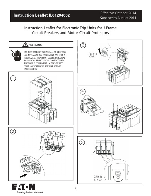
Circuit Breakers and Motor Circuit Protectors1DO NOT A TTEMPT TO INST ALL OR PERFORMMAINTENANCE ON EQUIPMENT WHILE IT ISENERGIZED.DEATH OR SEVERE PERSONALINJURY CAN RESUL T FROM CONT ACT WITHENERGIZED EQUIPMENT.ALWA YS VERIFYTHA T NO VOL T AGE IS PRESENT BEFOREPROCEEDING.42Push toClick75in-lb(8N•m)12011376-8in-lb (0.7-0.9N•m)EATON CORPORATION 2E ective October 2014Instruction Lea et IL01204002EE ective October 2014EATON CORPORATION .Trip UnitControls and Functions1.2.3.45.T est Port T est LED I -Continuous current setting t l I -(xI )switch LSI style LSIG style LSG style Status LED -A test port is built into each trip unit toallow use of a functional test kit.The test kit performs a test of the Long Delay,Short delay Ground Faultfunctions.-T o be used with a no trip functional test.This LED is a dual function light.As previously stated,the LED is used as a no trip indicator when using the test port.In normal modes,this LED indicates a high load alarm.It will light If the continuous current is 95%of the Ir Setting and must be present for a 38second duration..In accordance with standards requirements,the trip unit initiates a trip of the circuit breaker within 2hours for an overload of 135%and will trip as a function of l²t for higher currents.Continuous current values for eachlettered setting are indicated by the chart displayed on the right side of the trip unit label.-The number of seconds required to trip @6x I .,i.e.l -250A,t -2sec load current -1500A (6X).The breaker will trip in 2seconds.-Setting in multiples of l For short circuit condi-tions that exceed the short delay pick-up setting,the trip unit initiates a trip after a predetermined delay.The is the ground fault pick-up switch.It is used on the LSIG &LSG styles to set the ground fault pick-up as a percentage of I (frame current).For example,a 250A frame with an I (xI )setting of 0.4will provide a ground fault pick-up at 100A.For the ,the short delay time is a flat re-sponse determined by the t switch settings of INST,the LED is used as a no trip indicator when using the 120ms,or 300ms.For the LS styles,the short delay time is an I²t function.For the ,the short delay is a flat response determined by the t /t switch settings of INST,120ms or 300ms.This switch is a dual switch that also determines the ground fault time settings of INST,120ms or 300ms.For example,if the t /t switch is set at position J,then both short delay time and ground fault time are at INST flat.As another example,set the tSD/tG switch at position L;the short delay flat time is INST and the ground fault flat time is at 300ms.The LSIG label (see above 8a)should be used in conjunc-tion with the tSD/tG switch to set any one of ninepossible combinations of short delay and ground fault flat times.The LSIG label should be applied to the left side Breaker Frame Nameplate.For the ,the short delay time is an I²t function while the ground fault flat time is set by the t switch.-A green status light indicates theoperational status of the trip unit.If the load current exceeds approximately 20%of the maximum current rating (I the breaker,the status light will blink on and off once each second.r LD SD G N r r LD r.N G N SD SD G SD G G n 6.7.8.910..)3LSGLSILS11 . The High Load Alarm Relay option or the Ground Fault Alarm Only option will provide a SPST contact closure when the trip unit current equals or is greater than 95% of I n for a period of 38 seconds. If the current drops below the 95% value, the contact will open. The Ground Fault Alarm Only option operates i n a similiar fashion; the SPST contact will close if the ground f ault pick-up setting is exceeded and will open when below the ground fault pick-up setting. The yellow and green wires that exit the right side of the breaker are the common (C) and n ormally (NO) of this relay.12 . The Ground Fault Relay option will provide a SPST contact closure immediately before the breaker will trip on a ground fault over current detect. This closure is momentary (50ms) and the customer must provide the necessary external circuitry in order to latch this signal. The yellow and green wires that exit the right side of the breaker are the common (C) and normally (NO) of this relay.NOTE: The High Load Alarm Relay can be selected with LS, LSI, and LSG, LSIG trip units. For the LSG and LSIG trip units, the High Load Alarm will function as normal. [16.] However, if the breaker trips due to a ground fault condition, the relay will respond with a ground fault alarm as indicated in [17.].The Ground Fault Alarm Only can be selected for LSG and LSIG trip units only. This selection has precedence over all other relay functions.NOTE: The contact rating of the relay is: 250V AC@ 8 AMPS resistive load.13 . The Zone Selective Interlock (ZSI) option provides a wired method of coordinating Upstream and Downstream breakers. The coordinating signals are provided by the White\Red stripe (Zin), White\Black stripe (Zout), and Black (common ground) wires that exit the right side of the breaker.A typical connection (two breaker system is accomplished by connecting the Zout wire of the Downstream breaker to the Zin of the Upstream breaker. The common black wires of both breakers must also be connected.If a high current fault is sensed from the load on the Downstream breaker, both breakers will sense the fault. However, the Down-stream breaker will send the interlock signal to the Upstreamof both breakers. This delay allows the Downstream breaker to clear the fault without the Upstream breaker tripping. However, if for some reason the Downstream breaker does not clear the fault in the set delay time, the Upstream breaker will then clear the fault.NOTE: this option must be ordered from the factory. NOTE: Please see Balloon 8A and refer to 4-14. 14.Zone selective interlocking is provided for the short delay and the ground fault delay tripping functions for improved system protection. The JG/LG310+ Trip Unit zone selective interlocking feature is compatible with OPTIM and Digitrip Trip Units, Model 510 and higher. It is also compatible with Series G NG Trip Units, as well as, with FDE breakers.The zone selective interlocking feature is a means of communica-tions over a pair of wires between two or more compatible trip units. Zone selective interlocking makes it possible for pro-grammed trip unit settings to be altered automatically to respond to different fault conditions and locations, thereby localizing the effects of an interruption and providing positive coordination between circuit breakers.Three wires exit the breaker with the following color code and function: White/with Black Stripe=Zone Out, White/with Red Stripe=Zone In, and Black=Common.An example of a Zone Interlock system would be a J G310+. A breaker used as the upstream breaker and a 225A FDE breaker used as the downstream breaker. The Zout wire (white/black stripe) of the 225A breaker would be connected to the Zin wire (white/red stripe) of the J G310+ breaker. Also both common wired (black must be connected ). There could be more breakers added in a similar fashion to form a zone of protection.For faults outside the zone of protection, the trip unit of the circuit breaker nearest the fault sends an interlocking signal (Zout) to the trip unit of the up-stream circuit breaker. (Zin) This interlocking signal restrains immediate tripping of the upstream circuit breaker until its programmed coordination times is reached. Thus zone selective interlocking applied correctly can reduce damage due to circuit or ground fault conditions. A Table of the settings of the two breakers versus the outcomes (Both trip, Downstream (Dn) trips) of the breakers is indicated below for the conditions mentioned in the Table heading.NOTE: A single Series G or FDE breaker with the Zone In-terlocking feature enabled will not trip at the programmed time settings, unless Self Interlocked. That is, the Zout wire should be connected to the Zin wire.UpstreamINST120ms300ms DownstreamINST Both 43ms Dn 43ms Dn 43ms120ms Both 52ms Dn 52ms Dn 52ms300ms Both 43ms Dn 43ms Dn 43ms4002E Effective October 2014 EATON CORPORATION Page 4-95Neutral Current Sensor Installation100%Rated J-Frame Circuit BreakersGround fault trip units are supplied from the factory with pigtail lead connections for a neutral current sensor (white and grey wires).A neutral current sensor is available,but must be ordered separately.Series G Ground Fault Trip Units detect ground fault currents through Residual Sensing.They are not designed to use source ground or zero sequence ground fault sensing methods.If the system neutral isgrounded,but no phase to neutral loads are used,the neutral current sensor is not necessary.In that case,the white and grey leads on the trip should be cut off before installation.If the system neutral is grounded and phase to neutral loads are used,then the neutral current sensor (see Figure 9)must be used.It should be connected to the breaker according to the diagram in Figure 10.It has the same turns ratio as the phase current sensors in the trip unit.JG-C circuit breakers are suitable for continuous operation at 100%of the frame rating if used with CU only 90C insulated wire in an enclosure which measures at least 26”high x 18”wide x 8”deep.The polarity of the sensor connections is critical.Always observe the polarity markings on the installation drawings.The polarity markings are identified as white dots on the transformers.To insure correctground fault equipment performance,conduct field tests to comply with National Electric Code requirements under Article 230-95-C.°NOTICEEATON CORPORATION +Instruction Lea et IL01204002E Effective October 2014Instruction Leaflet IL01204002E Effective October 2014Eaton CorporationElectrical Sector1000 Cherrington ParkwayMoon Township, PA 15108United States877-ETN-CARE (877-386-2273)© 2014 Eaton CorporationAll Rights ReservedPrinted in USAPublication No. IL01204002EH07October 2014。
- 1、下载文档前请自行甄别文档内容的完整性,平台不提供额外的编辑、内容补充、找答案等附加服务。
- 2、"仅部分预览"的文档,不可在线预览部分如存在完整性等问题,可反馈申请退款(可完整预览的文档不适用该条件!)。
- 3、如文档侵犯您的权益,请联系客服反馈,我们会尽快为您处理(人工客服工作时间:9:00-18:30)。
ZDB智能电机保护器的安装与维护
0 引言
我厂有400多台电动机,通过五年运行的观察,ZDB智能电机保护器(以下简称ZDB保护器),能有效、及时、准确地显示电机运行中的故障,保护电机正常运行。
本文结合本厂实际,主要介绍ZDB保护器的性能,安装调试与维护。
1 ZDB保护器主要结构
ZDB保护器是目前国内低压电机保护器的最新产品。
它采用高性能单片机和DSP等国际上先进的集成电路和微机技术,保护功能齐全,参数设定简单,显示直观,带有R485串行通讯接口,可实现计算机通讯、检测、控制等功能。
2 ZDB保护器的主要功能
ZDB保护器具有过流、堵转、三相电流不平衡、断湘、过压、欠压等故障保护,它现场设定额定电压、启动时间,过压欠压值,过流保护动作时间、堵转电流对额定电流的倍数、漏电电流等参数,电机运行时,可以循环显示A、B、C三相电流值;保护状态时能对电机故障值记忆显示,对故障类别以字符方式显示。
它可将三相平均电流变换为4~20mA标准信号输出,变送量程可设定。
根据线程电机操作要求,ZDB保护器可以手动复位或自动复位,自动复位可自由设定。
3 ZDB保护器安装与设定
ZDB保护器自带互感器可以额定电流小于100A的电机,我厂搭配厂家生产的DBS型三联电流互感器,保护额定电流可以扩大到1000A。
ZDB保
护器安装方便,在盘前开孔:93*45mm,盘后用M4*2螺钉固定。
ZDB保护器端子线接线图如图1所示,1、2号端子线接交流或直流220V 电源,3、4号端子接电机控制回路停机保护节点,5、6接电机故障报警节点,7、8是电机漏电保护节点输入,9、10是RS485或4~20mA信号输入, 11~13端子是电机三相电流互感器输入,14是电流互感器的公共端。
ZDB保护器常闭节点一般接到主接触器线圈出现与零线连接的中间,这样当电机出现故障时保护常闭节点断开,接触器线圈失电,接触器主回路断开电源,电机停止运转。
保护器在电机启动及运行时,按设置键无效。
不启动电动机,保护器按通电源按键设置。
此时设置等亮,保护器显
“C0000”,用“移位”和“数据”按键配合输入密码“1997”,再按设置键进入设置状态。
选择类型,然后依次按移位键,选择数据移位,按数据键进行数据修改。
某参数设定完毕,再按设置键,进入下一项设置状态直至结束。
所有参数设定完毕后,按复位键,退出设置状态,显示OFF。
常用功能设置显示如表1所示:
平时我们设置的时候,没有特殊要求就进入保护器,把电流值改到电机的额定电压即可,其它系统默认参数即可满足生产要求。
4 电机的故障与处理
ZDB保护器外形如图2所示,电机正常运行时,ZDB保护器LED显示屏按时自动循环显示三相住回路电流和漏电电路。
电机出现故障时,LED 首位显示相应的故障代码,在发出跳闸信号前不停闪烁,动作后显示相应的故障类型及电机电流、电压值,故障指示灯亮。
ZDB保护器的故障字符显示有A、E、[、?%J、└┘、┌┐、┐、L。
LED显示A后加数字,故障灯亮。
表示电机过流保护器动作,一般检查电机连接机械部分,大部分是由于电机拖动的负载过多,引起电流增大。
(1)LED显示E,故障灯亮。
表示电机机械堵转保护器动作,先检查电机带电机是否能盘动,不能盘动时脱开电机前轴所连接的机械部分,再盘电机。
有时候电机轴承卡死,也引起保护器堵转保护。
(2)LED显示[,故障灯亮时。
表示电动机断相保护器动作,这时断开主回路的电源,先检查主回路供电相是否正常,其次用500M?%R的绝缘摇表检查电机接触器到电机三相负荷线的绝缘,那一相相间绝缘与其他两项绝缘不为零,表示该相有故障。
字符?%J表示电流不平衡故障,└┘表示过压,┌┐表示欠压,┐表示短路、L表示漏电。
通过这些代码,可以更准确的判断出故障类型,找出解决方案。
5 结束语
电机出现故障不能及时发现和处理,不仅对设备长期运行不利,还影响生产产量。
ZDB保护器不仅费用低,维护更换方便,还能快速反出应设备故障并显示出故障代码,增加了维护人员查找故障加效率,及早清除故障,避免电机停车影响生产效率。
希望以上资料对你有所帮助,附励志名言3条:
1、上帝说:你要什么便取什么,但是要付出相当的代价。
2、目标的坚定是性格中最必要的力量源泉之一,也是成功的利器之一。
没有它,天才会在矛盾无定的迷径中徒劳无功。
3、当你无法从一楼蹦到三楼时,不要忘记走楼梯。
要记住伟大的成功往
往不是一蹴而就的,必须学会分解你的目标,逐步实施。