英特费斯 牌 荷重传感器 “INTERFACE” Load Cells
(爱斯顿)荷重仪_

5、吨位仪系统接线:
按照系统操作说明书将系统的电源线、报警信号线、凸轮信号线、传感器线
连接到 HELM 吨位仪上。
注意:
1) 系统上电之前,先用万用表测试电源是否正确;
2) 系统上电之前,先将滑块处于上死点位置;
3) 报警输出信号为:24V DC 开关量,一般不能直接接入控制电路,如
果采用,需要外加中间继电器进行相关转换;
南京市江宁经济开发区将军大道 155 号
TEL:025-52785976 FAX:025-52785576
此功能为特殊需要,设置为--P。 --P=0% 表示目前不使用本功能。
7:转速切换
LO
CORNER 按切换键。 SELECT 到下一个项目。
UP DOWN
按上下选择 HI/LO。 冲床 SPM 超过 200 时设定为 HI 冲床 SPM 在 200 以下时设定为 LO。
1、手动零点调节:
手动零点调整步骤,请参照下页图例,每个通道的自动调零/标定开关位于内部 电源板上。具体对应关系为:LF(CH1,通道 1,为左前)、LR(CH2,通道 2,为左后)、
RF(CH3,通道 3,为右前)、RR(CH4,通道 4,为右后)。
1) 将 电 源 板 上 的 自动调零/标定开关(金 属 连 杆 开 关 ) 拨到中间 OFF 位置;
4
ESTUN 埃斯顿
南京市江宁经济开发区将军大道 155 号
ESTUN DIGITAL TECHNOLOGY CO.,LTD
TEL:025-52785976 FAX:025-52785576
调节设置好该参数后,将 SETTINGS 开 关 S2 打 到 左 边 位 置 ( 位 于 门 后
面 ), 保 存 设 置 参 数 。
赫特尔 HPC-100CT-2系列胶囊式水位传感器说明书
Doc. no : HT(HPC)100CT2_IM_Eng_Rev.2Issue date: 2020. 02HITROL CO., LTD.HEAD OFFICE.FACTORY .R&D INSTITUDE HITROL CO.,LTD. 141, Palhakgol-gil, Jori-eup Paju-si, Gyeonggi-do, Korea TEL. : (00)-82-31-950-9700 FAX. : (00)-82-31-943-5600 INSTRUCTION MANUALCAPACITANCE TYPE LEVEL TRANSMITTERHT-100CT-2 Series HPC-100CT-2 SeriesTable of contentsOverview (3)Characteristics (3)Operating Principle (3)Specifications (4)Weather-Proof Version (4)Ex -Proof Version (4)Amplifier Specification (5)Product Composition & Technical Data (6)Installation (8)Metal Tanks (10)Non-metal Tanks (10)Wiring & AMP Composition (11)Failure Check & Maintenance (18)Product Check (18)Failure Check (18)Precautions for Removal (18)Precautions for Transportation & Assembly .. 19 Precautions for Installation (19)Precautions for Grounding ......... 19 Safety and Environment (19)Marking (20)User Training (20)Warranty and Contact (20)OverviewCharacteristicsOperating Principle■Widely used to measure various liquid levels■Strong structure and semi-permanent life cycle due to moveless part■Various probe types for wide application■Easy installation of wire type. (HT-100CTW-2)■Applicable to corrosive liquid■Interface measurement between water and oil is available■Applicable to explosive area (HPC-100CT-2 Series)■Have KC certificate and CE certificateHT(HPC)-100CT-2 Series is a Capacitance Type Level Transmitter which continuously measures liquid levels using of liquid’s dielectric constant. It can be easily installed and adjusted, and can be easily applied to corrosive liquids and widely used in general industries, chemical and oil plants.When there are two conductors insulated each other, the value of capacitance formed between two conductors is a function of the sizes of two conductors, relative location of two conductors and the dielectric constant of material placed between two conductors. Under the conduction that air of dielectric ε₁exists in the space between two concentric conductors, lower part of space between two conductors is filled material of dielectric constant ε₂as shown below, the change of capacitance is expressed as follows.ΔC =Since is a constant value as an initial condition, and get this value as K, ΔC becomes a function of level of material only. Therefore, level can be obtained through the measurement of ΔC.log D/d10(ε₂- ε₁X l)[pF]10log D/d(ε₂- ε₁): Dielectric constant of air: Dielectric constant of medium (contents): Height of tank: Level of medium (contents): Outer diameter of tank: Outer diameter of sensing probeε₁ε₂LIDdSpecifications Weather-Proof VersionEx-Proof VersionAmplifier SpecificationProduct Composition & Technical DataMaterial :PBT(Aluminum) [Housing][Connection] Material : AluminumDielectric Constant Valuewebsite .InstallationThe capacitance type level transmitter can be installed in screw (PT, NPT, PF) and flange (ANSI, JIS, DIN) as well as tri-clamp and other various locations. Pay attention to the following matters during installation.■ Product shall be installed at the place far from inlet in order to avoid the malfunction.(a) ■ Protection tube shall be applied if there is a flow or slopping of the medium of the tank. (b) ■ Probe shall be installed within Max. 300mm from the tank wall and ground tube type shall be applied if the distance between the tank wall and sensing probe is far or the tank material is non-conductive. (c)■ Ground rod type shall be used for corrosive liquid. (d)■ Bracket insulated to a sensing probe shall be installed at the bottom of probe in order tofix it if the probe length is long or there is slopping of medium in the tank. (e)■ Ground tube or ground rod type shall be applied for concrete or non-conductive tank as per above figure. (g)■ Ground tube type shall be applied for ball tank and external chamber shall be installed forside mounting of tank. (h)■ When side mounting, the chamber shall be installed. (i)(g)(i)(h)■Metal Tanks (Conductive tank)When installing on a conductive tank, the transmitter housing and tank shall be grounded as shown below.■Non-metal tanks (Non-conductive tank)When installed on a non-conductive tank, use the ground tube (rod) or ground wire type.Also, the transmitter housing and tank shall be grounded as shown below.Wiring & AMP Composition■ Set Menu Function: Level : Distance0.0 ~ 95.0% or 4.000 ~ 19.200 mA setting [T able 1] Setting Menu List■ Module Composition- Make sure to connect the power with correct polarity (+, -), and the power supply shall be between +17V ~ 40V . - Do not connect the wire with the power connected.1. S : Function setting / Save the setting2. M : Mode Change / Cancellation3. ▲ : Span Set / Setting the value left / up4. ▼ : Zero Set / Setting the value right / down5. LCD : Display of operating and setting status6. LED : Display of power and status7. UART : Communication port of HT-100CT-2 setup and operation status 8. PWR : For supply power and current output / check for output current 9.N/A : Not used■ Operating methodThe cursor moves sequentially whenever the button is pressed. The order of movement is as follows.mA → % → m → ft → → → mA → % →…□ Into the Setting MenuIn the Setting Mode, press button for 1 second then the green LED will be flickering and you can go into the Setting Menu.□ Return to the Setting ModeIn the Setting Menu, press button for 1 second then the green LED will be flickering and you can go back to the Setting Mode.□ Select the Setting Menu⏹ In the Setting Menu, use / buttons to select the user setting function. ⏹Pressingbutton for 1 second will enter the function.About 1 sec./About 1 sec.About 1 sec. Display mode Cursor SegmentBar graph(User setting)(User setting)□ Change the User SettingIf just 1 digit is flickering , it can be moved between the digits. If full digits are flickering , it can only be set up to the specified number.□ User Key Button■ Height SettingChange of digitsand valueLevelThis refers to the direction in which the medium is raised based on the bottom of the tank.Zero HeightThe distance from the bottom of the tank to the zero point is called “Zero Height ”.Span HeightThe distance from the bottom of the tank to the span point is called “Span Height ”.T ank HeightThe distance from the bottom of the tank to the top of the tank is called “T ank Height DistanceThis refers to the direction of the downing of the medium from the top of the tank.[T able 2] Key Button Guidance□ Zero, Span Quick Setting■ Zero Setting■ Span Setting■ Others▶ Zero & Span can be set regardless of display mode status▶ It can set, save, and cancel the values. (Refer to T able 2) ▶ The level shall not be changed when Zero & Span are setting.mA SettingPercent Setting■ UART MonitoringYou can only check the state of the adjusted setting values using your PC or Smartphone, and the execution method is the same. (Password: 1975)Run screen configuration: You can check the sensor measurement status, sensitivity setting value, relay setting status, etc.■ Monitoring using a PCComponent – PC, USB Extension cable (typical USB to Micro USB B), UART ADAPTORZero SettingSpan SettingPress for 1 sec.Press for 1 sec.Press for 1 sec.Press for 1 sec.Input the valueInput the value[USB Extension cable][HT-100CT-2 PC UART Compositions]No. No. ContentsContentsSettingSetting[HT-100CT-2 PC UART Launch Screen Compositions]OutputInput[A Description of the Current Operating Status (##Err State)][HT-100CT-2 PC UART Launch Screen Compositions Function]Unit SetSetSet SetHeight Set (Based on level)Height Set (Based on level) Height Set (Based on level)Function SetSetAdjustmentAdjustmentAdjustmentSelectResetCapacity Value of Current MeasuredCapacity Value of Span SettingCapacity Value of Zero SettingCurrent Output of Current V alue (01. B a s e d o n O u t p u t S e l e c t S e t t i n g ) Current Output of P ercentage V alue (01. B a s e d o n O u t p u t S e l e c t S e t t i n g )Current Output of Length V alue (01. B a s e d o n O u t p u t S e l e c t S e t t i n g )Current Output of Feet V alue (01. B a s e d o n O u t p u t S e l e c t S e t t i n g )Current Operating StateNormal operationProblem for sensing B el ow or ab ov e t he set v a l ue o f Z er o or S p a n Abnormal settingSensor cable open circuit, short, broken probe insulation, module sensor failure, etcNAMUR ME43 Caution area (below 4mA, above 20mA)Zero, Span conversely set stateNo.ContentsDescriptionRemarks■Monitoring using a SmartphoneComponent – Smartphone (Android OS), OTG, USB Extension cable (typical USB to Micro USB B), UART ADAPTORApplication – Refer to “Serial USB Terminal Install & Setting Guide”[USB Extension cable][HT-100CT-2 Smartphone UART Compositions][Enter PW and Fly command]Continue[Open App] [Home screen] [Select the UART Connection] [Enter the password] [Operation screen][HT-100CT-2 Smartphone UART Launcher][Enter exit and Fly command][Enter exit command] [End of program] [Select the UART Disconnection][HT-100CT-2 Smartphone UART Exit]Failure Check & MaintenancePrecautions For Removal ■Check the level and presence of medium in the tank before removing it.■Wear gloves when removing it, to prevent a burn.■If there is explosive gas atmosphere, do not open the cover.■Disassemble work shall be done with the power off.■Make sure than any O-ring or gasket is not damaged while opening or closing the cover of product.■Product CheckThe major parts of the HT(HPC)-100CT-2 Series level transmitters to be inspected are divided into the sensor element and the transmission element. The life spans of major parts vary with user environments and can be used in optimum conditions through periodic inspections. Therefore, the user shall maintain and repair the product through periodic inspections conducted at least once a year. In addition, check for the exterior of the product like visual damage. If the medium or foreign substance is attached to the probe, it will cause bad accuracy, so it shall be removed regularly. Be careful not to damage the Teflon part during removal.■Failure CheckThe level of measured object changes, but the output does not change.▶Insufficient power supply▶Wrong adjustment of ZERO and SPANOnly a slight change of output to the change of level of medium is present.▶Wrong adjustment of ZERO and SPAN▶A slight change of probe ΔC valueNo change of level, but output fluctuation is present.▶Wrong grounding▶Noise on the lines▶Extreme fluctuation of medium▶Bad insulation of probeOutput indicates full (20mA) of higher regardless of the change of level of the medium.▶Wrong adjustment of ZERO and SPANPrecautions forT ransportation& AssemblyPrecautions for InstallationPrecautions for Grounding (Ex-proof)Safety and Environment ■Precautions for Use- Make sure to connect the product and vessel using required tools for sure.- Keep the lock key safe and make sure that it is locked.- Do not apply high impact to the product.■Precautions for Wiring- Make sure to wire contacts correctly. (Refer to Wiring)- Wire and supply the power to the device after checking the specifications.- Pay attention to prevent electric shock.■Disposal of Product- Make sure to separate the amplifier and main unit from housing before disposing the products. Also, the amplifier shall be detached and discard the metal and non-metallic materials. No part (ex. Mercury switch) has influence on the environment, so no special attention is required.■Pay special attention to prevent any impact on the device during transportation or assembly.■Pay attention to prevent any damage to any packing when transporting or mounting the machine to the vessel.■Use the same standard flange or screw.■Make sure to insert washers between bolts and nuts to prevent loosening.■Make sure to insert gaskets between flanges.(Select the gaskets in consideration of temperature of content and pressure of vessel.)■Install an Ex-proof product only in an Ex-proof zone.■After the installation is complete and the cover of the product is assembled, power it on.Please do not apply high impact to the product.■When connecting to an external ground, the ground wire shall be 4㎟(4mmSQ).Make sure to insert a washer if the terminal lug is removed from ground terminal and then re-connected. (Loosening prevention)HEAD (Weather-proof) HEAD (Ex-proof)External ground 4㎟(4mmSQ)MarkingUser TrainingWarranty and Contact■Warranty and ServiceThis product is subject to the warranty for 2 years of shipments and unpaid service will be provided for any damage found under normal operating conditions. If it is not about the failure of product, the service charge will be payable.You can request A/S at our website or by contacting our headquarters.■Headquarters ․Factory ․Laboratory Contact NumberAddress: HITROL CO., LTD 141, Palhakgol-gil, Jori-eup, Paju-si, Gyeonggi-do, Korea TEL: 031-950-9700 (Headquarters & A/S)FAX: 031-950-9796 ~ 9799 (Headquarters & A/S)■Product Identification- The product identification mark is attached onto the housing and shows the model name, serial number, working temperature, working pressure, and matters regarding output. The serial number is a unique manufacturing number for the identification of products.The fluid temperature of the container shall be up to 80℃for Weather-proof type. For high temperature, the fluid temperature shall not exceed 150℃. In addition, make sure that the ambient temperature of housing is kept at -20℃~ +60℃.An Ex-proof product is pressure-resistant and Ex-proof type, so never open the coverduring operation.Do not apply the Non Ex-proof product in an Ex-proof zone.Ex-proofWeather-proof。
芬斯特-芬斯斯产品说明书:NJ15-30GM50-E2-V1-3G-3D 型号的非沉入式感应传感器

12R e l e a s e d a t e : 2 0 1 6 -11 -0 7 1 0 : 02 Da t e o f i s s u e : 2 0 1 6 -1 1 -0 7 1 2 9 8 5 1 _ e n g . x m lPinoutL+L-13421 BN2 WH3 B U4 BKWire colors in accordance with EN 60947-5-2(brown)(white)(blue)(black)3R e l e a s e d a t e : 2016-11-07 10:02D a t e o f i s s u e : 2016-11-07129851_e n g .x m lInstructionManual electrical apparatus for hazardous areas Device category 3G (nA) for use in hazardous areas with gas, vapour and mist Certificate of ComplianceCE marking ATEX marking ¬ II 3G Ex nA IIC T6 GcThe Ex-related marking can also be printed on the enclosed label.Standards EN 60079-0:2012+A11:2013, EN 60079-15:2010 Ignition protection category "n"Use is restricted to the following stated conditionsG eneralThe apparatus has to be operated according to the appropriate data in the data sheet and in this instruction manual. The data stated in the data sheet are restricted by this operating instruction! The special conditions must be observed!Installation, commissioningLaws and/or regulations and standards governing the use or intended usage goal must be observed. If the Ex-related marking is printed only on the supplied label, then this must be attached in the immediate vicinity of the sensor. The sticking surface for the label must be clean and free from grease. The attached label must be legible and indel-ible, including in the event of possible chemical corrosion.MaintenanceNo changes can be made to apparatus, which are operated in hazardous areas.Repairs to these apparatus are not possible.Special conditionsMaximum operating current I L The maximum permissible load current must be restricted to the values given in the fol-lowing list. High load currents and load short-circuits are not permitted.Maximum operating voltage U BmaxThe maximum permissible operating voltage UB max is restricted to the values in the following list. T olerances are not permissible.Maximum permissible ambient temperature T Umax dependant of the load current I L and the max. operating voltage U Bmax Information can be taken from the following list. at U Bmax =60 V , I L =200 mA 50 °C (122 °F) at U Bmax =60 V , I L =100 mA 54 °C (129.2 °F) at U Bmax =30 V , I L =200 mA54 °C (129.2 °F)Protection from mechanical danger The sensor must not be exposed to ANY FORM of mechanical danger.Protection from UV light The sensor and the connection cable must be protected from damaging UV-radiation. This can be achieved when the sensor is used in internal areas.Protection against transients Ensure transient protection is provided and that the maximum value of the transient pro-tection (140% of 85 V) is not exceeded.Electrostatic chargeElectrostatic charges must be avoided on the mechanical housing components. Dan-gerous electrostatic charges on the mechanical housing components can be avoided by incorporating these in the equipotential bonding.Material selection accessories When selecting accessories, ensure that the material allows the temperature of the enclosure to rise to up to 70 °C.Plug connectorThe plug connector must not be withdrawn under voltage. The proximity switch is identi-fied as follows: "WARNING - DO NOT SEPARATE WHEN ENERGIZED". With the plug connector disconnected, soiling of the internal area must be prevented.(i.e. the area that is inaccessible when the connector is inserted)4Releasedate:216-11-71:2Dateofissue:216-11-7129851_eng.xml Note This instruction is only valid for products according to EN50281-1-1, valid until 30-September-2008Note the ex-marking on the sensor or on the enclosed adhesive labelInstruction Manual electrical apparatus for hazardous areasDevice category 3DCE markingATEX marking ¬ II 3D IP67 T 89 °C (192.2 °F) XStandards EN50281-1-1Protection via housingUse is restricted to the following stated conditionsG eneral The apparatus has to be operated according to the appropriate data in the data sheet and in this instruction manual.The data stated in the data sheet are restricted by this operating instruction! The special conditions must be adhered to! Installation, commissioning Laws and/or regulations and standards governing the use or intended usage goal must be observed.Maintenance No changes can be made to apparatus, which are operated in hazardous areas.Repairs to these apparatus are not possible.Special conditionsMaximum operating voltage U Bmax The maximum permissible operating voltage UBmax must be restricted to the values given in the following list. T olerances arenot permitted.Maximum operating current I L The maximum permissible load current must be restricted to the values given in the following list.High load currents and load short-circuits are not permitted.Maximum heating (T emperature rise) dependant of the load current I L and the max. operating voltage U BmaxInformation can be taken from the following list. The maximum surface temperature at maximum ambient temperature is givenin the Ex identification of the apparatus.at U Bmax=60 V, I L=200 mA 19 Kat U Bmax=60 V, I L=100 mA 15 Kat U Bmax=30 V, I L=200 mA 15 KProtection from mechanical danger The sensor must not be mechanically damaged.Electrostatic charge Electrostatic charges must be avoided on the mechanical housing components. Dangerous electrostatic charges on themechanical housing components can be avoided by incorporating these in the equipotential bonding.Plug connector The plug connector must not be disconnected under voltage. The proximity switch is marked as follows: "DO NOT DISCON-NECT UNDER VOLTAGE!" When the plug connector is disconnected the ingress of dirt into the inner areas (i.e. the areas,which are not accessible in the plugged-in condition) must be prevented.The plug connection can only be separated using a tool. This is achieved by using the locking protection V1-Clip (Mountingaccessory from Pepperl + Fuchs).5R e l e a s e d a t e : 2016-11-07 10:02D a t e o f i s s u e : 2016-11-07129851_e n g .x m lNote This instruction is only valid for products according to EN 61241-0:2006 and EN 61241-1:2004 Note the ex-marking on the sensor or on the enclosed adhesive label InstructionManual electrical apparatus for hazardous areas Device category 3DCE marking ATEX marking ¬ II 3D Ex tD A22 IP67 T80°C XThe Ex-significant identification is on the enclosed adhesive label Standards EN 61241-0:2006, EN 61241-1:2004 Protection via housing "tD"Use is restricted to the following stated conditionsG eneralThe apparatus has to be operated according to the appropriate data in the data sheet and in this instruction manual.The maximum surface temperature has been determined in accordance with method A without a dust layer on the equipment.The data stated in the data sheet are restricted by this operating instruction!The special conditions must be adhered to!Installation, commissioningThe statutory requirements, directives and standards applicable to the intended use and application must be observed.The adhesive label provided must be affixed in the immediate vicinity of the sensor! The surface to which the label is applied must be clean, flat and free from grease! The affixed adhesive label must be readable and durable, taking account of the possi-bility of chemical corrosion!MaintenanceNo changes can be made to apparatus, which are operated in hazardous areas.Repairs to these apparatus are not possible.Special conditionsMaximum operating current I L The maximum permissible load current must be restricted to the values given in the following list.High load currents and load short-circuits are not permitted.Maximum operating voltage U Bmax The maximum permissible operating voltage UBmax must be restricted to the values given in the following list. T olerances are not permitted.Maximum permissible ambient tempera-ture T Umaxdependant of the load current I L and the max. operating voltage U Bmax Information can be taken from the following list. at U Bmax =60 V , I L =200 mA 50 °C (122 °F) at U Bmax =60 V , I L =100 mA 54 °C (129.2 °F) at U Bmax =30 V , I L =200 mA54 °C (129.2 °F)Protection from mechanical danger The sensor must not be exposed to ANY FORM of mechanical danger.Protection from UV light The sensor and the connection cable must be protected from damaging UV-radiation. This can be achieved when the sensor is used in internal areas.Electrostatic charge Electrostatic charges must be avoided on the mechanical housing components. Dangerous electrostatic charges on the mechanical housing components can be avoided by incorporating these in the equipotential bonding.Plug connectorThe plug connector must not be withdrawn under voltage. The proximity switch is identified as follows: "WARNING - DO NOT SEPARATE WHEN ENERGIZED". With the plug connector disconnected, soiling of the internal area must be prevented.(i.e. the area that is inaccessible when the connector is inserted) The plug connection can only be separated using a tool.This is achieved by using the locking protection V1-Clip (Mounting accessory from Pepperl + Fuchs).6Releasedate:216-11-71:2Dateofissue:216-11-7129851_eng.xml Instruction Manual electrical apparatus for hazardous areasDevice category 3D for use in hazardous areas with combustible dustCertificate of ComplianceCE markingATEX marking ¬ II 3D Ex tc IIIC T80°C DcThe Ex-related marking can also be printed on the enclosed label.Standards EN 60079-0:2012+A11:2013, EN 60079-31:2014Protection by enclosure "tc" Some of the information in this instruction manual is morespecific than the information provided in the datasheet.G eneral The corresponding datasheets, declarations of conformity, EC-type examination certifi-cates, certifications, and control drawings, where applicable (see datasheets), form anintegral part of this document. These documents can be found at www.pepperl-. The maximum surface temperature of the device was determined without alayer of dust on the apparatus. Some of the information in this instruction manual is morespecific than the information provided in the datasheet.Installation, commissioning Laws and/or regulations and standards governing the use or intended usage goal mustbe observed. If the Ex-relevant identification is printed exclusively on the adhesive labelprovided, this label must be affixed in the immediate vicinity of the sensor! The back-ground surface to which the adhesivelabel is to be applied must be clean and free fromgrease! The applied label must be durable and remain legible, with due consideration ofthe possibility of chemical corrosion!Maintenance No changes can be made to apparatus, which are operated in hazardous areas.Repairs to these apparatus are not possible.Special conditionsMaximum operating current I L The maximum permissible load current must be restricted to the values given in the fol-lowing list.High load currents and load short-circuits are not permitted.Maximum operating voltage U Bmax The maximum permissible operating voltage UBmax must be restricted to the valuesgiven in the following list. T olerances are not permitted.Maximum permissible ambient temperature T Umax dependant of the load current I L and the max. operating voltage U BmaxInformation can be taken from the following list.at U Bmax=60 V, I L=200 mA 50 °C (122 °F)at U Bmax=60 V, I L=100 mA 54 °C (129.2 °F)at U Bmax=30 V, I L=200 mA 54 °C (129.2 °F)Protection from mechanical danger The sensor must not be exposed to ANY FORM of mechanical danger.Protection from UV light The sensor and the connection cable must be protected from damaging UV-radiation.This can be achieved when the sensor is used in internal areas.Electrostatic charge Electrostatic charges must be avoided on the mechanical housing components. Dan-gerous electrostatic charges on the mechanical housing components can be avoided byincorporating these in the equipotential bonding. Avoid electrostatic charges that cancause electrostatic discharge when installing or operating the device. Information onelectrostatic hazards can be found in the technical specification IEC/TS60079-32-1. Donot attach the nameplate provided in areas where electrostatic charge can build up. Plug connector The plug connector must not be withdrawn under voltage. The proximity switch is identi-fied as follows: "WARNING - DO NOT SEPARATE WHEN ENERGIZED". With the plugconnector disconnected, soiling of the internal area must be prevented.(i.e. the area thatis inaccessible when the connector is inserted)。
loadcells[详细讲解]
![loadcells[详细讲解]](https://img.taocdn.com/s3/m/f23a170b58eef8c75fbfc77da26925c52cc59121.png)
load cells广州南创蔡工load cells称重传感器实际上是一种将质量信号转变为可测量的电信号输出的装置。
用传感器茵先要考虑传感器所处的实际工作环境,这点对正确选用称重传感器至关重要,它关系到传感器能否正常工作以及它的安全和使用寿命,load cells乃至在整个衡器的可靠性和安全性。
在称重传感器主要技术指标的基本概念和评价方法上,新旧国标有质的差异。
Load cells分类:Load cells称重传感器按转换方法分为光电式Load cells、液压式Load cells、电磁力式Load cells、电容式Load cells、磁极变形式Load cells、振动式Load cells、陀螺仪式Load cells、电阻应变式Load cells等8类,以电阻应变式Load cells使用最广。
全球称重传感器总汇(load cells) :您还在为自己找不到load cells(称重传感器)所以品牌而烦恼吗?下面对各知名品牌load cells(称重传感器)进行了以下汇总:美国Load cells:AmCells Load cells Ametek AMTI Apollo Research Corp ATI Industrial AutomationArtech Industries IncLoad cells Cooper Instrument Systems Load cells DJ InstrumentsDytran Instrument Inc Load cells Futek Advanced Sensor Inc Load cells Geokon IncHardy Instruments Inc Load cells Helm Instrument Co Load cells GW Instruments IncKistler-Morse(KM) Kulite Semiconductor Load cells Load Cell CentralMagnetic Power Systems Inc Magtrol Inc Load cells Measurement Specialists IncMorehouse Instrument CoLoad cells Michigan Scientific CorporationOmega Engineering RDP Electronic Sensors Schneider Electric-Kavlico SensorsSensoe System Solutions Inc(ACSI) Load cells SensorData Technologies Inc Serena Industries IncSinger Instruments Control IncLoad cells Load cells Soltec CorporationStrainsert StressTek IncSensor Developments IncLoad cells Load cells Toledo Integrated Systems Load cells Transcell Technology IncS.Himmelstein and Company JLM Instrument Arpege-Masterk AKO IncCardinal Scale Mfg.Co Load cells Celesco Transducer Checkline英国Load cells:Applied Measurements Ltd(AML) Control Transducers Ltd Halma Group-Thames Side-MaywoodRDP ElectronicS-Sensors Techni Measure Mecmesin Limited Industrial Measurements LtdDEM Machines Procter and Chester Measurements Ltd(PCM)Load cells LCM Systems Ltd德国Load cells:Burster Gmbh Honigmann Tension MeterLoad cells Lorenz Messtechnik GmbH ME-Messsysteme GmbHPeekel Instruments A.S.T Angewandte SYSTEM-TECHNIK法国Load cells:Scaime IncLoad cells Precia MolenLoad cells日本Load cells:Kyowa Sensor Systems Unipulse CorporationLoad cells Kistler Japan Load cells Sohgoh Keiso NTS Tokyo Sokki Kenkyujo韩国Load cells:C&M Robotics Hitrol Bongshin Loadcell意大利Load cells:Gefran ISILoad cells N.B.C.ElettronicaLoad cells Laumas Electtronica AEP Transducers DINI ArgeoLoad cells瑞典Load cells:Vetek ABLoad cells台湾Load cells:Arico(Gefran) Algol(NTS) EsenseLoad cellsLoad cells称重传感器的选择:Load cells称重传感器在选用时要考虑到很多因素,实际的使用当中我们主要从下列几个因素考虑。
Utilcell MOD460-30T称重传感器

Utilcell MOD460-30T称重传感器广州南创房工西班牙Utilcell公司至今已成立近30年,已经给世界各地提供了近一百万个称重传感器。
自成立以来,西班牙Utilcell称重传感器的产品远销38个国家,在多个国家设立了分支机构或办事处,生产基地遍布美洲、东欧、中国等地;并在中国设立了广州南创传感器事业部,可为用户的实验和生产提供最佳的服务与解决方案。
西班牙Utilcell称重传感器产品信息:不锈钢结构前角多管系统的调整优化.可选 ATEX EX version压式称重传感器, 柱式标准量程:100-200-400t3000 divisions O.I.M.L. R60 class C密封焊接,防护等级 IP 68 ( EN60529 ).西班牙Utilcell称重传感器参数支持:标准量程:100-200-400t精度等级:1000n. OIML额定输入电压: 10 V最大输入电压: 15 V温度补偿: -10 to +40 °C温度范围: -20 to +70 °C输入阻抗: 800 ± 300 Ohm输出阻抗: 700 ± 30 Ohm空载输出<±2%Sn最小静载:0% Ln负载:120% Ln总误差<±0.05%Sn安装负载限制:150% Ln绝缘电阻 > 5000 MOhm重复性误差 <±0.015%Sn最大偏差(at Ln):1.4-2.6mm温度零度漂移 <±0.01%Sn/5K标称灵敏度(Sn): 2± 0.5% mV/V灵敏度温差影响 < <±0.018%Sn/5K蠕变误差(30分钟)<±0.048%Sn/5KUtilcell MOD460-30T称重传感器具体型号:MOD540-2t MOD540-3t MOD540-6t MOD540-10tMOD740-15t MOD740-20t MOD740-25t MOD740-30t MOD740-40t MOD740-60t MOD740-100t MOD740-200t MOD740-300t MOD740-400tMOD740D-15t MOD740D-30T MOD740D-40T MOD740D-60T ;Utilcell MOD460称重传感器图片:MOD540-2t MOD540-3t MOD540-6t MOD540-10tMOD550-2t MOD550-3t MOD550-6t MOD550-10tMOD700-10t MOD700-15t MOD700-20t MOD700-25t MOD700-30t MOD700-40t MOD700-50t MOD700-60t MOD740-70t MOD700-100t MOD740-150t MOD700-200tMOD650-250kg MOD650-500kg MOD650-1000kg MOD650-2000kg MOD650-5000kgMOD650-7500KGMOD740-15t MOD740-20t MOD740-25t MOD740-30t MOD740-40tMOD740-60t MOD740-100t MOD740-200t MOD740-300t MOD740-400tMOD740D-15t MOD740D-30T MOD740D-40T MOD740D-60TMOD750-7.5t MOD750-10t MOD750-15t MOD750-20t MOD750-25t MOD750-30t MOD750I-7.5t MOD750I-10t MOD750I-15t MOD750I-20t MOD750I-25t MOD750I-30tUtilcell MOD460-30T称重传感器技术参数以《OIML60号国际建议》92年版为基础,最新具体变化可查看《JJG669—Utilcell广州南创传感器事业部检定规程》Utilcell称重传感器介绍:工程机械搅拌设备称重系统的基本要求和特殊要求,提出了工程机械搅拌设备称重系统选用称重传感器时需要考虑的几个问题,重点分析了传感器防护结构对工程机械搅拌设备运行可靠性的影响,指出IP代码所代表的防护等级不能涵盖工程机械搅拌设备对传感器的全部防护要求。
申克皮带秤仪表VEG20610说明书(原文翻译)

1、目录1、概述 (1)讲述皮带秤操作原理及具体情况,如“出料点供料”。
什么是INTECONT? (1)详细资料 (1)定义 (1)计量原理 (1)控制 (2)输入和输出 (3)2、技术数据和字符 (5)本章简要介绍INTECONT 所用全部数据和所有可能发生的情况。
技术数据 (5)接口 (6)对话语言、单位 (7)显示、指示灯 (7)程序设置、标定 (8)3、程序设置 (9)程序设置功能便于以少量的运算完成秤体计量要求。
功能分配 (9)标定功能 (9)皮带环行LB (10)除皮TW (10)置零 (11)砝码检查CW (12)模拟方式 (13)时间设置.......................................... 13 4、服务值 (14)服务值信号适用外部线缆、输入、输出转换和负荷传感哭负载等检查。
另外,SPC值(生产过程控制统计)可用于喂料记录等方面。
5、参数 (15)确定设备特性,参数可满足特殊要求,甚至在停电时,他们亦能无限期的存贮。
总述 (17)调入参数 (17)装入初始参数 (18)参数概述 (19)注解参数表 (22)6、出现事件信号后错误诊断(故障信息) (45)大多数错误以及大部分操作状态均以事件信号的形式出现。
错误查询表帮助操作者迅速找出错误并及时恢复正常操作状态。
系统信息S...S9 (45)物料流量B...B9 (45)电气系统E...E5 (46)标定C1...C3 (46)最大值H1...L4 (46)最小值L1...L4 (47)信号灯 (47)7、使用 (48)全面介绍,逐步解释了应该进行的工作。
另外,你还会发现可能隐含的错误。
操作学习 (48)机械要求 (49)电器要求 (49)输入参数 (50)控制 (51)功能检查 (52)标定 (53)用砝码检查 (53)带速检查 (54)物料检查 (54)测试插座 (55)机械部分安装与调试 (55)1、概述什么是INTECONT?INTECONT PLUS是用于计量、控制、喂料设备的计量计算系统。
O2 传感器 4100 e 说明书

Instruction manual O2Transmitter 4100 eOrder number: 52 121 114ContentsMettler-Toledo GmbH, Process Analytics, Industrie Nord,CH-8902 Urdorf, Tel. (01) 736 26 36Subject to technical changes. Mettler-Toledo GmbH, 10/03.WarrantyDefects occurring within 1 year from delivery date shall be remedied free of charge at our plant (carriage and insurance paid by sender).Subject to change without noticeDisposal (Directive 2002/96/EC of January 27, 2003)Please observe the applicable local or national regulations concerning the disposal of “waste electrical and electronic equipment”.ContentsSafety information Array Be sure to read and observe the following instruc-tions!The device has been designed in accordance with the state ofthe art and complying with the applicable safety regulations.When operating the device, certain conditions may neverthe-less lead to danger for the operator or damage to the device.Caution!Commissioning may only be carried out by trained experts.Whenever it is likely that protection has been impaired, thedevice shall be made inoperative and secured against unintend-ed operation.The protection is likely to be impaired if, for example:•the device shows visible damage•the device fails to perform the intended measurements•after prolonged storage at temperatures above 70 °C•after severe transport stressesBefore recommissioning the device, a professional routine testin accordance with EN 61010-1 must be performed. This testshould be carried out by the manufacturer.Intended useThe O2Transmitter 4100 e is used for dissolved oxygen and tem-perature measurement in biotechnology, pharmaceutical industry, as well as in the field of environment, food processing, and sewage treatment.The rugged molded enclosure can be wall or pipe mounted or fixed into a control panel.The protective hood provides additional protection against direct weather exposure and mechanical damage.The Transmitter has been designed for application with ampero-metric sensors of the InPro6000 ... InPro6800 Series. TrademarksThe following names are registered trademarks. For practical rea-sons they are shown without trademark symbol in this manual. InPro®EasyClean®EC Declaration of conformityOverview of O 2Transmitter 4100 eDo not connect!CathodeGuardAnodeReference electrode RTDRTDshieldHOLD HOLD/CONTROL CONTROL+ Output 1- Output 1/2+ Output 2Relay 1Relay 1/2Relay 2AlarmAlarmClean Clean Power PowerPackage contentsCheck the shipment for transport damage and completeness. The package should contain:• Front unit• Lower case• Bag containing small parts• Instruction manual• Specific test reportAssemblyFig.: Pipe-mount kitPipe mounting, panel mountingInstallation and connectionCaution!•Installation may only be carried out by trained experts in accordance with this instruction manual and as per applicable local and national codes.•Be sure to observe the technical specifications and input ratings.•Be sure not to notch the conductor when stripping the insulation.•Before connecting the device to the power supply, make sure that its voltage lies within the range 20.5 to 253 V AC/DC.•When commissioning, a complete configuration must be carried out by the system administrator.The terminals are suitable for single wires and flexible leads upto 2.5 mm2(AWG 14)Warning!Additional safety precautions have to be taken for applications in hazardous locations to CSA (CLI DIV2 GPA,B,C,D T4, Ex nA IIC T4)!(See Pg 93.)Protective wiring of switching contactsRelay contacts are subjected to electrical erosion. Especially with inductive and capacitive loads, the service life of the con-tacts will be reduced. For suppression of sparks and arcing,components such as RC combinations, nonlinear resistors,series resistors and diodes should be used.Protective wiringA: DC application with inductive loadB: AC/DC applications with capacitive load C: Connection of incandescent lampsA1Inductive loadA2Free-wheeling diode, e.g. 1N4007 (Observe polarity)A3ContactB1Capacitive loadB2Resistor, e.g. 8 Ohms/1 W at 24 V / 0.3 A B3ContactC1Incandescent lamp, max 60 W / 230 V , 30 W / 115 V C3ContactWarning!Make sure that the maximum ratings of the relay contacts are not exceeded even during switching!Typical protective wiring measuresProtective wiringUser interface, displayDisplayOperation: KeypadSensocheck, Sensoface sensor monitoringSensocheck continuously monitors the sensor and leads.Sensocheck can be switched off (Configuration, Pg 46).Safety featuresMode codesThe mode codes allow fast access to all functions CalibrationOverview of configuration stepsNote:The Transmitter 4100 e has a device a resolution of 0.01 ppm. For the sensor type B, we recommend the O2Transmitter 4100ppb with a device resolution of 0.001 ppm.Polarization voltage. Process pressure. Salt correction.Two complete parameter sets are stored in the EEPROM. As delivered, the two sets are identical but can be edited. Note:Fill in your configuration data on the following pages.Default settings of parameter setsCode. Parameter Setting o1. Sensor type ________________________o1. %, mg/l, ppm ________________________o1. 0/4-20 mA________________________o1. Current beginning ________________________o1. Current end ________________________o1. Filter time ________________________o1. 22mA signal ________________________o1. Hold behavior ________________________o1. Fix current ________________________o2. Unit °C / °F ________________________o2. Temp probe ________________________o2. 0/4...20mA________________________o2. Current beginning ________________________o2. Current end ________________________o2. Filter time ________________________o2. 22mA signal ________________________o2. Hold behavior ________________________o2. Fix current________________________Co. Polarization voltage ________________________Co. Pressure unit ________________________Co. Pressure ________________________Co. Salinity ________________________CA. Cal mode ________________________CA. Cal interval ________________________AL. Sensocheck ________________________AL. Alarm delay ________________________AL. LED Hold________________________Parameter set – user settingsCode. Parameter Setting rL. Relay function ________________________L1. Contact function ________________________L1. Contact response ________________________L1. Switching point ________________________L1. Hysteresis ________________________L1. Delay________________________L2. Contact function ________________________L2. Contact response ________________________L2. Switching point ________________________L2. Hysteresis ________________________L2. Delay________________________Ct. Setpoint ________________________Ct. Neutral zone ________________________Ct. P action ________________________Ct. I action ________________________Ct. D action________________________Ct. PLC/PFC controller ________________________Ct. Pulse length ________________________Ct. Pulse frequency ________________________Ct. Hold behavior ________________________Pb. Probe selection ________________________Pb. Rinsing interval ________________________Pb. Rinse duration ________________________Pb. Contact type ________________________Pb. Cleaning interval________________________Pb. Lock cleaning interval________________________It is always recommended to calibrate in air.Compared to water, air is a calibration medium which is easy to handle, stable, and thus safe. In the most cases, however, the sensor must be dismounted for a calibration in air.When dealing with biotechnological processes which require sterile conditions, the sensor cannot be removed for calibration. Here, calibration must be performed with aeration directly in the process medium (e.g. after sterilization).The calibration procedures for these two common applications are described on the following pages. Of course, other combina-tions of process variable and calibration mode are possible.Note:When a 2-point calibration is required, the zero point calibration should be performed prior to saturation or concentration cali-bration, resp.All calibration procedures must be performed by trainedpersonnel.Zero point calibrationNote:In Hold mode the controller output acts as configured (Y = const. or Y = 0).50 %X w10 / (1.00)20 / (2.00)30 / (3.00)40 / (4.00)50 / (5.00) ControlleroutputYProportional action (Gradient K C[%])Neutral zone (Y=0)Tolerated deviation from setpoint.The setting “010%”, for example, permits a deviation of ±5 % from the desired value without activating the controller.Pulse length / pulse frequency controllerPulse length controller (PLC)The pulse length controller is used to operate a valve as an actuator. It switches the contact on for a time that depends on the controller output. The period is constant. A minimum ON time of 0.5 sec is maintained even if the controller output takes corresponding values.Pulse frequency controller (PFC)The pulse frequency controller is used to operate a frequency-controlled actuator. It varies the frequency with which the contacts are switched on. The maximum pulse frequency [pulses/min] can be defined. It depends on the actuator.The Contact ON time is constant. It is automatically calculated from the user-defined maximum pulse frequency:Output signal (switching contact) of pulse frequency controllerOutput signal (switching contact) of pulse length controllerOperation with automatic cleaning system“EasyClean” is a separate automatic cleaning system. The cleaning cycle is activated according to the cleaning interval defined during configuration (Pg 55).Calibration error messagesNoteThe worsening of a Sensoface criterion leads to the devaluation of the Sensoface indicator (Smiley becomes “sad”). An improvement of the Sensoface indicator can only take place after calibration or removal of a sensor defect.SensocheckContinuously monitors the sensor and lines for short circuits or open circuits. Critical values make the Sensoface “sad” and the corresponding icon flashes:The Sensocheck message is also output as error messageErr33. The alarm contact is active, the red LED is lighted, out-put current 1 is set to 22 mA (when configured corresponding-ly). Sensocheck can be switched off during configuration (then Sensoface is also disabled). Exception: After a calibration aAppendixProduct line and accessoriesDevices Order No. O2Transmitter 4100 e52 121 103 Mounting accessoriesPipe-mount kit52 120 741 Panel-mount kit52 120 740 Protective hood52 120 739 SensorsMettler-Toledo GmbH, Process Analytics offers a wide range of sensors for the following fields of applications:- Chemical process industry- Pharmaceutical industry- Food and beverage industry- Water/waste-waterFor more information concerning our sensors and housings program, please refer to .DO input Sensor Type A: InPro6000 – 6800Sensor Type B:InPro6900Measuring current-2 to 1800 nA,Resolution 0.05nA(with Vpol = 800 mV and Vref = 200 mV)Saturation (-10 to 80 °C)0 to 500 %Meas. error1,2,30.5 % meas.val. + 0.5 %Concentration (-10 to 80 °C)0.00 to 50.00 mg/l0.00 to 50.00 ppmMeas. error1,2,30.5 % meas.val. + 0.05 mg/lor 0.05 ppmAdm. guard current≤20 µAPolarization voltage*0 to 1000 mV,Process pressure *0.000 to 9.999 bars(to 999.9 kPa / to 145.0 psi)Salt correction *00.00 to 45.00 g/kgSensor standardizationOperating modes *DO saturation (automatic)DO concentration (automatic)Product calibrationZero point calibrationCalibration range Zero point±2 nASensor Type A Slope25 to 130 nA(at 25 °C, 1013 mbars)Calibration range Zero point±2 nASensor Type B Slope200 to 550 nA(at 25 °C, 1013 mbars)Calibration timer *0000 to 9999 hPressure correction *0.000 to 9.999 bars / 999.9 kPa / 145.0 psiSensocheck Monitoring for short circuits / open circuits (can be disabled)Sensoface Provides information on the sensor conditionEvaluation of zero/slope, response,calibration interval, Sensocheck Temperature NTC 22 kOhms / NTC 30 kOhms, selectableinput2-wire connection, adjustableMeasurement range-20.0 to +150.0 °C / -4 to +302 °FAdjustment range10 KResolution0.1 °C / 1 °FMeas. error1,2,3< 0.5 K (<1 K at > 100°C)HOLD input Galv. separated (OPTO coupler)Function Switches Transmitter to HOLD modeSwitching voltage Inactive0 to 2 V (AC/DC)Active10 to 30 V (AC/DC) CONTROL input Galv. separated (OPTO coupler)Function Control input for automatic cleaning system Switching voltage Inactive0 to 2 V (AC/DC)Active10 to 30 V (AC/DC) Output 10/4 to 20 mA, max. 10 V, floating(galv. connected to output 2)Process variable *DO saturation/DO concentrationOverrange *22 mA in the case of error messagesOutput filter *Low-pass, filter time constant 0 to 120 sMeas. error 1< 0.3 % current value + 0.05 mAStart/end of scale Configurable within selected rangeAdm. span 5 to 500 % / 0.5 to 50 mg/l (ppm)Output 20/4 to 20 mA, max. 10 V, floating(galv. connected to output 1)Process variable TemperatureOverrange *22 mA in case of temp error messagesOutput filter *Low-pass, filter time constant 0 to 120 sMeas. error 1< 0.3 % current value + 0.05 mAStart/end of scale*-20 to +150 °C / -4 to +302 °FAdm. span 20 to 170 K (68 to 338 °F)Alarm contact Relay contact, floatingContact ratings AC< 250 V / < 3 A / < 750 VADC< 30 V / < 3 A / < 90 WContact response N/C (fail-safe type)Response delay *0000 to 0600 sLimit values Output via relay contacts R1, R2Contacts R1, R2 floating but inter-connected Contact ratings AC< 250 V / < 3 A / < 750 VADC< 30 V / < 3 A / < 90 WContact response*N/C or N/OResponse delay *0000 to 0600 sSwitching points*Within selected rangeHysteresis*000.0 to 050.0 % / 00.00 to 05.00 mg/l (ppm)PID Output via relay contacts R1, R2process controller(Relay R1: below setpoint,Relay R2: above setpoint)Setpoint specification*0 to 500 % / 0.00 to 50.00 mg/l (ppm)Neutral zone*000.0 to 050.0 % / 00.00 to 05.00 mg/l (ppm)P-action component*Controller gain Kp: 0010 to 9999 %I-action component*Reset time Tr:0000 to 9999 s(0000 s = no integral action) D-action component*Rate time Td: 0000 to 9999 s(0000 s = no derivative action) Controller type*Pulse length controller or pulse frequency controller Pulse period*0001 to 0600 s, min. ON time 0.5 s(pulse length controller)Max. pulse frequency*0001 to 0180 min-1(pulse frequency controller)Cleaning function*Relay contact, floating, for controlling a simple rinsingsystem or an automatic cleaning system (EasyClean) Contact ratings AC< 250 V / < 3 A / < 750 VADC< 30 V / < 3 A / < 90 WContact response*N/C or N/OInterval *000.0 ... 999.9 h(000.0 h = cleaning function switched off)Rinse duration*0000 ... 1999 sDisplay LC display, 7-segment with iconsMain display Character height 17 mm, unit symbols 10 mm Secondary display Character height 10 mm, unit symbols 7 mmSensoface 3 status indicators (friendly, neutral, sad Smiley)Mode indicators 5 status bars“meas”, “cal”, “alarm”, “cleaning”, “config”18 further icons for configurationand messagesAlarm indication Red alarm LED in case of alarm or HOLD (user defined) Keypad 5 keysService functionsCurrent source Current specifiable for output 1 and 2 (00.00 to 22.00 mA) Manual controller Controller output entered directly (start of control process) Device self-test Automatic memory test (RAM, FLASH, EEPROM)Display test Display of all segmentsLast Error Display of last error occurredSensor monitor Display of direct, uncorrected sensor signalRelay test Manual control of the four switching contactsParameter sets Two selectable parameter sets for differentapplicationsData retention Parameters and calibration data > 10 years (EEPROM)Protection against Protective separation of all extra-low-voltage circuits against electrical shock mains by double insulation as per EN 61010-1Power supply24 (-15%) to 230 V AC/DC (+10%); approx. 5 VA, 2.5 WAC: 45 to 65 Hz; Overvoltage category II, Class IINominal operating conditionsAmbient temperature-20 to +55 °CTransport/Storage temp.-20 to +70 °CRelative humidity 10 to 95 % not condensingPower supply24 (-15%) to 230 V AC/DC (+10%)Frequency for AC45 to 65 HzEMC EN 61326Emitted interference Class B (residential environment)Class A for mains supply > 60 V DCImmunity tointerference IndustrialenvironmentExplosion protectionFM: NI Class I Div 2 Group A, B, C & D,T4T a = 55 °C; T ype 2NI Class I Zone 2Group IIC,T4 T a = 55°C; T ype 2CSA:Class I Div 2 Groups A, B, C and D,T4Ex nA IIC T4Enclosure Molded enclosure made of PBT (polybutylene terephtalate) Color Bluish gray RAL 7031Assembly• Wall mounting• Pipe mounting: dia 40 to 60 mm, 30 to 45 mm• Panel mounting, cutout to DIN 43 700Sealed against panelDimensions H 144 mm, B 144 mm, T 105 mmIngress protection IP 65 / NEMA 4XCable glands 3 breakthroughs for cable glands M20x1.52 breakthroughs for NPT 1/2 “orRigid Metallic ConduitWeight Approx. 1 kg*) User-defined) To IEC 746 Part 1, at nominal operating conditions) ±1 count) Plus sensor errorExplosion protectionWarnings and notesto ensure safe operation2-point calibration . . . . . . . . . . . . . . . . . . . . . . . . . . . . . .6122 mA signal for error message . . . . . . . . . . . . . .37, 43, 78Accessories . . . . . . . . . . . . . . . . . . . . . . . . . . . . . . . . . . . .85Alarm settings . . . . . . . . . . . . . . . . . . . . . . . . . . . . . . . . . .46Alarm contact . . . . . . . . . . . . . . . . . . . . . . . . .46, 88, 78Alarm delay . . . . . . . . . . . . . . . . . . . . . . . . . . . . . . . . . 47Error messages . . . . . . . . . . . . . . . . . . . . . . . . . . . . . . .78Operating states . . . . . . . . . . . . . . . . . . . . . . . . . . . . . .80Assembly . . . . . . . . . . . . . . . . . . . . . . . . . . . . . . . . . . . . .10Cal timer . . . . . . . . . . . . . . . . . . . . . . . . . . . . . . . . . . . . . .47Calibration . . . . . . . . . . . . . . . . . . . . . . . . . . . . . . . . . . . .61Calibration to concentration (Conc) . . . . . . . . . . . . . . . .64Calibration to saturation (SAT) . . . . . . . . . . . . . . . . . . . .62Display of calibration data . . . . . . . . . . . . . . . . . . . . . . .71Specify calibration mode . . . . . . . . . . . . . . . . . . . . . . . .47Cleaning system . . . . . . . . . . . . . . . . . . . . . . . . . . . . . . . .77Configuration . . . . . . . . . . . . . . . . . . . . . . . . . . . . . . . .54Lock cleaning interval . . . . . . . . . . . . . . . . . . . . . . . . . .54Configuration . . . . . . . . . . . . . . . . . . . . . . . . . . . . . . . . . .26Configuration steps . . . . . . . . . . . . . . . . . . . . . . . . . . . .28Menu structure . . . . . . . . . . . . . . . . . . . . . . . . . . . . . . .27Configuration: Alarm settings . . . . . . . . . . . . . . . . . . . . . .46Alarm delay . . . . . . . . . . . . . . . . . . . . . . . . . . . . . . . . . .47LED in HOLD mode . . . . . . . . . . . . . . . . . . . . . . . . . . . .47Sensocheck . . . . . . . . . . . . . . . . . . . . . . . . . . . . . . . . . .47Configuration: Correction . . . . . . . . . . . . . . . . . . . . . . . . .44Polarization voltage . . . . . . . . . . . . . . . . . . . . . . . . . . . .44Process pressure . . . . . . . . . . . . . . . . . . . . . . . . . . . . . .44Salt correction . . . . . . . . . . . . . . . . . . . . . . . . . . . . . . . .44Configuration: Calibration mode . . . . . . . . . . . . . . . . . . .46Cal timer interval . . . . . . . . . . . . . . . . . . . . . . . . . . . . . .47Configuration: Controller . . . . . . . . . . . . . . . . . . . . . . . . .52IndexConfiguration: Limit function . . . . . . . . . . . . . . . . . . . . . .48Settings for relay 1 . . . . . . . . . . . . . . . . . . . . . . . . . . . .48Settings for relay 2 . . . . . . . . . . . . . . . . . . . . . . . . . . . .50Use of relays . . . . . . . . . . . . . . . . . . . . . . . . . . . . . . . . .49Configuration: Output 1 . . . . . . . . . . . . . . . . . . . . . . . . . .30Measurement procedure . . . . . . . . . . . . . . . . . . . . . . . .30Output current during Error . . . . . . . . . . . . . . . . . . . . . .36Output current range . . . . . . . . . . . . . . . . . . . . . . . . . .32Output signal during HOLD . . . . . . . . . . . . . . . . . . . . . .37Select sensor type . . . . . . . . . . . . . . . . . . . . . . . . . . . . .30Time constant of output filter . . . . . . . . . . . . . . . . . . . . .34Configuration: Output 2 . . . . . . . . . . . . . . . . . . . . . . . . . .38Output current during HOLD . . . . . . . . . . . . . . . . . . . . .42Set output current range . . . . . . . . . . . . . . . . . . . . . . . .39Temperature error . . . . . . . . . . . . . . . . . . . . . . . . . . . . .42Temperature probe . . . . . . . . . . . . . . . . . . . . . . . . . . . .39Temperature unit . . . . . . . . . . . . . . . . . . . . . . . . . . . . . .38Time constant of output filter . . . . . . . . . . . . . . . . . . . .40Configuration: Rinsing and calibration probes . . . . . . . . . .54Control drawing . . . . . . . . . . . . . . . . . . . . . . . . . . . . .94, 96Controller . . . . . . . . . . . . . . . . . . . . . . . . . . . . . . . . . . . . .74Configuration . . . . . . . . . . . . . . . . . . . . . . . . . . . . . . . .62Controller equations . . . . . . . . . . . . . . . . . . . . . . . . . . .75Controller test . . . . . . . . . . . . . . . . . . . . . . . . . . . . . . . .73Pulse length / pulse frequency controller . . . . . . . . . . . .74Controller: behavior during HOLD . . . . . . . . . . . . . . . . .53Current source 1/2 . . . . . . . . . . . . . . . . . . . . . . . . . . . . . .72Diagnostics functions . . . . . . . . . . . . . . . . . . . . . . . . . . . .71Controller test . . . . . . . . . . . . . . . . . . . . . . . . . . . . . . . .73Display of calibration data . . . . . . . . . . . . . . . . . . . . . . .71Display of last error message . . . . . . . . . . . . . . . . . . . . .71Display of output currents . . . . . . . . . . . . . . . . . . . . . . .71Display of sensor current . . . . . . . . . . . . . . . . . . . . . . . .71。
interface传感器
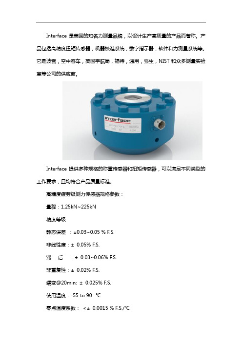
Interface是美国的知名力测量品牌,以设计生产高质量的产品而著称。
产品包括高精度扭矩传感器,机器校准系统,数字指示器,软件和力测量系统等。
它是波音,空中客车,美国宇航局,福特,通用,强生,NIST和众多测量实验室等公司的供应商。
Interface提供多种规格的称重传感器和扭矩传感器,可以满足不同类型的工作要求,且均符合产品质量标准。
高精度疲劳级测力传感器规格参数:
量程:1.25kN~225kN
精度等级
静态误差:±0.03~0.05 % F.S.
非线性度:±0.05% F.S.
滞后:±0.03~0.06% F.S.
非重复性:±0.02% F.S.
蠕变@20min: ±0.025% F.S.
使用温度:-55 to 90 ℃
零点温度系数:<±0.0015 % F.S./℃
输出温度系数:< ±0.0015 % F.S./℃
输出灵敏度:1.0/2.0 mV/V
激励电压:最大20Vdc
桥路电阻:350Ω
零点平衡:±1.0%F.S.
绝缘电阻: >5000Ω
过载保护: ±300% F.S.
加工精度误差mm 0.05。
郑州沐宸自动化科技有限公司致力于力传感器及信号处理的系统工作,公司在力传感器领域有着不断的追求。
主要有Interface传感器、多维力传感器、扭矩传感器、位移传感器、压力传感器、加速度传感器、液位传感器等,同时可根据客户的需求,定制各类传感器。
- 1、下载文档前请自行甄别文档内容的完整性,平台不提供额外的编辑、内容补充、找答案等附加服务。
- 2、"仅部分预览"的文档,不可在线预览部分如存在完整性等问题,可反馈申请退款(可完整预览的文档不适用该条件!)。
- 3、如文档侵犯您的权益,请联系客服反馈,我们会尽快为您处理(人工客服工作时间:9:00-18:30)。
9300型 重量指示器
最多显示6个数位 显示范围: 60,000 可设置测量单位,包括 磅,公斤, 安士等 可连接最多八个荷重 传感器 电源: 230V AC
9840型 指示器
最多显示6个数位 显示范围: ±999,999 分辨度: 24位元(bits) 可设置测量单位,包 括磅,公斤, 安士等 模拟输出±10V DC RS-232界面 电源: 230V AC
“英特费斯”牌 荷重传感器 “INTERFACE” Load Cells
美 国 制 造
Made in USA
美国 INTERFACE 公司是制造测力器的领导者,曾经以超过二十年的时间将公司之全部资源专门用于 设计和生产应变仪,荷重传感器及力的测量系统,所制造出来的荷重传感器具有高效率,高精度,可 预测,可信赖等优点,适用于: 所有各种型式的电子磅称, 批料控制, 个数计算, 称量检核等仪器 在工程试验中测量推力, 转矩, 应力 材料疲劳, 耐力, 拉力试验 科学研究 安全性和过程控制的施力和应力监测
浙 江 科 通 仪 器 有 限 公 司 (绍 兴 ) Tel: (86 575) 8812 0560 Fax: (86 575) 8812 0561 浙 江 科 通 仪 器 有 限 公 司 (广 州 ) Tel: Fax: (86 20) 8130 7388 (86 20) 8108 4925 上海香科仪器贸易有限公司
Tel: (86 21) 6248 6170 Fax: (86 21) 6248 0647
“英特费斯”牌 荷重传感器 “INTERFACE” Load Cells
美 国 制 造
Made in USA
低轮廓型荷重传感器 Low Profile Load Cells 特性是不受侧面力,弯曲力,扭转力和温度的影响 可补偿大气压力 体积小巧 有对称的输出 能抵抗外力 可附加: (请在订购前选定) 输出效率高 1.保护底座 能保持真正线性 2.超荷重保护(只限有底座型号) 能维持长时间的稳定性 3.接头保护 及抗疲劳特性 偏移性低 图中显示是有底座型号→ 具温度稳定性
单点式荷重传感器 Single Point Load Cell
坚固,可靠,高效 可供全天候和可冲洗环 在受控制的环境中可以 防水型,低成本的精密系 对偏心荷重不敏感, 能,在受控制的环境 境,轧屑回收池及露天使 直线式装配 列,直线式装配可供应拉 适合应用于不含杆、 中安装,成本低 用 力型或压力型 轴或弯件的测重 超精密度 供瞬时间高冲 精密的效能 超精密度 超精密度 击力应用 最佳线性 防水功能 最佳线性 最佳线性 可重复性高 耐腐蚀性 可重复性高 可重复性高 蠕变低 不受气压影响 具备温度补偿 具备温度补偿 转矩敏感度低 小巧坚固 转矩敏感度低 转矩敏感度低 具备温度补偿 容易装配 价格低廉 价格低廉 价格低廉 价格低廉 容易装配 容易装配 小巧坚固 适合全天候及垂直 防水功能 空间小的场合使用 容易装配 不受气压影响 型号 荷重量(lb) 型号 荷重量(lb) 型号 荷重量(lb) 型号 荷重量(lb) 型号 荷重量(lb) MB-5 SSB-50 SM-10 SSM-50 SP1-3 5英磅 50英磅 10英磅 50英磅 3英磅 MB-10 SSB-100 SM-25 SSM-100 SP1-7.5 10英磅 100英磅 25英磅 100英磅 7.5英磅 MB-25 SSB-250 SM-50 SSM-250 SP1-15 25英磅 250英磅 50英磅 250英磅 15英磅 MB-50 SSB-500 SM-100 SSM-500 SP1-25 50英磅 500英磅 100英磅 500英磅 25英磅 MB-75 SSB-1000 SM-250 SSM-750 SP1-50 75英磅 1000英磅 250英磅 750英磅 50英磅 MB-100 100英磅 SSB-2500 SM-500 SSM-1000 2500英磅 500英磅 1000英磅 SP1-100 100英磅 MB-150 150英磅 SSB-5000 SM-1000 5000英磅 1000英磅 SSM-2000 2000英磅 SP1-150 150英磅 MB-250 250英磅 SSB-10000 10000英磅 3000英磅 荷重量(N) SSM-3000 SM-50N SSM-5000 50牛顿 5000英磅 SM-100N 100牛顿 荷重量(N) SM-200N SSM-200N 200牛顿 200牛顿 SM-500N SSM-500N 500牛顿 500牛顿 SM-1000N SSM-1000N 1000牛顿 1000牛顿 SM-2000N 2000牛顿 SSM-2000N 2000牛顿 SM-5000N 5000牛顿 SSM-5000N 5000牛顿 SSM-10KN 10000牛顿 SSM-20KN 20000牛顿 <-常 规 是 压 力 校 准, 如 需 拉 力 校 准 请 特 别 指 明 --> 只有压力校准
Shanghai Xiang Ke Scientific Trading Co. Ltd
香港科学仪器社有限公司 Tel: (852) 2481 1323 Fax: (852) 2418 1302
Che Scientific Co. (Hong Kong) Ltd. Zhejiang Fortune Scientific Co. Ltd. (Shaoxing) Zhejiang Fortune Scientific Co. Ltd. (Guangzhou)
1000系列 抗疲劳荷重传感器 Fatigue Rated Load Cell
结合优质材料,特别工序,严格检验和最先进的设计概念制造出最好的荷重传感器,可以承受一亿次全反向荷重 循环而不发生故障。
型号 荷重量(英磅) 1010-250 250 1010-500 500 1010-1K 1,000 1010-2.5K 2,500 1010-5K 5,000 1020-12.5K 12,500 型号 1020-25K 1032-50K 1040-100K 1044-135K 1050-200K 1050-300K 荷重量(英磅) 25,000 50,000 100,000 135,000 200,000 300,000 型号 1010-1.25KN 1010-2.5KN 1010-5KN 1010-12.5KN 1010-25KN 1020-50KN 荷重量(牛顿) 1,250 2,500 5,000 12,500 25,000 50,000 型号 1020-125KN 1020-225KN 1040-450KN 1044-600KN 1050-900KN 1060-1500KN 荷重量(牛顿) 125,000 225,000 450,000 600,000 900,000 1500,000
Tel: (86 21) 6248 6170 Fax: (86 21) 6248 Indicator
9320型 便携式指示器
最多显示7个数位 显示范围:±9,999,999 分辨度: 24位元(bits) 最高/最低显示 电源: 2 x AA 电池
9820型 指示器
最多显示5个数位 显示范围: ±99,999 分辨度: ±19,999 可 连 接 最 多 四 个 350Ω荷重传感器 模拟输出±10V DC 电源: 230V AC
香港科学仪器社有限公司 Tel: (852) 2481 1323 Fax: (852) 2418 1302 浙 江 科 通 仪 器 有 限 公 司 (绍 兴 ) Tel: (86 575) 8812 0560 Fax: (86 575) 8812 0561 浙 江 科 通 仪 器 有 限 公 司 (广 州 ) Tel: Fax: (86 20) 8130 7388 (86 20) 8108 4925 上海香科仪器贸易有限公司
1100系列 超精密荷重传感器 Ultra Precision Load Cell
高精准度荷重传感器是测力校准系统的理想配备。
可测量压力及拉力型号 型号 荷重量(英磅) 型号 荷重量(牛顿) 1110-300 1110-1.5KN 300 1,500 1110-500 1110-2.5KN 500 2,500 1110-1K 1110-5KN 1,000 5,000 1110-2K 1110-10KN 2,000 10,000 1110-5K 1110-25KN 5,000 25,000 1110-10K 1110-50KN 10,000 50,000 1120-25K 1120-100KN 25,000 100,000 1120-50K 1120-250KN 50,000 250,000 1132-100K 1132-450KN 100,000 450,000 1140-200K 1140-900KN 200,000 900,000 型号 1111-1K 1111-2K 1111-5K 1111-10K 1121-25K 1121-50K 可测量压力型号 荷重量(英磅) 型号 1111-5KN 1,000 1111-10KN 2,000 1111-25KN 5,000 1111-50KN 10,000 1121-100KN 25,000 1121-250KN 50,000 荷重量(牛顿) 5,000 10,000 25,000 50,000 100,000 250,000
MB 系列
横梁式荷重传感器 Minibeam Load Cell
SSB 系列
密封横梁式荷重传感器 Sealed Superbeam Load Cell
SM 系列
微荷重传感器 Supermini Load Cell
SSM 系列
密封式超微荷重传感器 Sealed Supermini Load Cell
SPI 系列
Shanghai Xiang Ke Scientific Trading Co. Ltd
Che Scientific Co. (Hong Kong) Ltd. Zhejiang Fortune Scientific Co. Ltd. (Shaoxing) Zhejiang Fortune Scientific Co. Ltd. (Guangzhou)